check oil YAMAHA XV950 2014 Owners Manual
[x] Cancel search | Manufacturer: YAMAHA, Model Year: 2014, Model line: XV950, Model: YAMAHA XV950 2014Pages: 88, PDF Size: 2.37 MB
Page 6 of 88

TABLE OF CONTENTSSAFETY INFORMATION.................. 1-1
DESCRIPTION .................................. 2-1
Left view ......................................... 2-1
Right view ....................................... 2-2
Controls and instruments ............... 2-3
INSTRUMENT AND CONTROL
FUNCTIONS ...................................... 3-1
Immobilizer system......................... 3-1
Main switch .................................... 3-2
Indicator lights and warning lights............................................ 3-3
Multi-function meter unit ................ 3-5
Handlebar switches ........................ 3-8
Clutch lever .................................. 3-10
Shift pedal .................................... 3-10
Brake lever.................................... 3-10
Brake pedal .................................. 3-11
ABS (for ABS models) .................. 3-11
Fuel tank cap ................................ 3-12
Fuel ............................................... 3-13
Fuel tank breather/overflow
hose .......................................... 3-14
Catalytic converter ....................... 3-14
Steering lock................................. 3-15
Rider seat ..................................... 3-16
Adjusting the shock absorber assemblies ................................ 3-17
Sidestand ..................................... 3-17
Ignition circuit cut-off system ....... 3-18 FOR YOUR SAFETY –
PRE-OPERATION CHECKS
............. 4-1
OPERATION AND IMPORTANT
RIDING POINTS ................................ 5-1
Starting the engine .......................... 5-1
Shifting ............................................ 5-2
Tips for reducing fuel consumption ................................ 5-3
Engine break-in ............................... 5-3
Parking ............................................ 5-4
PERIODIC MAINTENANCE AND
ADJUSTMENT ................................... 6-1
Owner’s tool kit ............................... 6-2
Periodic maintenance chart for the emission control system .............. 6-3
General maintenance and lubrication chart ........................... 6-4
Removing and installing the
panel ............................................ 6-8
Checking the spark plugs ............... 6-8
Engine oil and oil filter cartridge.... 6-10
Replacing the air filter element ..... 6-13
Checking the throttle grip free play ............................................ 6-13
Valve clearance ............................. 6-14
Tires .............................................. 6-14
Cast wheels................................... 6-16
Adjusting the clutch lever free play ............................................ 6-16 Checking the brake lever free
play ............................................ 6-17
Brake light switches ..................... 6-18
Checking the front and rear brake pads .......................................... 6-18
Checking the brake fluid level ...... 6-19
Changing the brake fluid .............. 6-20
Drive belt slack ............................. 6-21
Checking and lubricating the cables ........................................ 6-21
Checking and lubricating the
throttle grip and cable ............... 6-22
Checking and lubricating the brake and shift pedals............... 6-22
Checking and lubricating the brake and clutch levers ............. 6-23
Checking and lubricating the
sidestand................................... 6-23
Lubricating the swingarm pivots......................................... 6-24
Checking the front fork ................. 6-24
Checking the steering................... 6-25
Checking the wheel bearings ....... 6-25
Battery .......................................... 6-26
Replacing the fuses ...................... 6-27
Replacing the headlight bulb ........ 6-29
Tail/brake light .............................. 6-30
Replacing a turn signal light bulb ........................................... 6-31
License plate light......................... 6-31U2DEE0E0.book Page 1 Friday, June 14, 2013 1:29 PM
Page 18 of 88
INSTRUMENT AND CONTROL FUNCTIONS
3-3
3
WARNING
EWA10073
Never turn the key to “OFF” while
the vehicle is moving, otherwise the
electrical systems will be switched
off, which may result in loss of con-
trol or an acci dent.
EAU57660
(Parkin g)
The hazard lights and turn signal lights
can be turned on, but all other electri-
cal systems are off. The key can be re-
moved.
EAU49394
In dicator li ghts an d warnin g
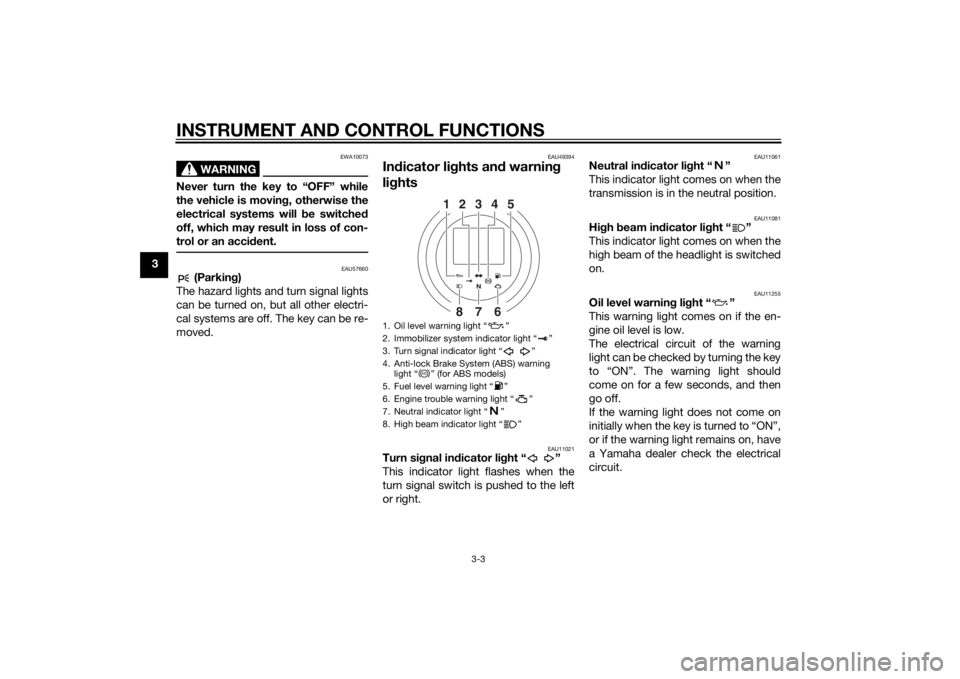
li g hts
EAU11021
Turn si gnal in dicator li ght “ ”
This indicator light flashes when the
turn signal switch is pushed to the left
or right.
EAU11061
Neutral in dicator li ght “ ”
This indicator light comes on when the
transmission is in the neutral position.
EAU11081
Hi gh beam in dicator li ght “ ”
This indicator light comes on when the
high beam of the headlight is switched
on.
EAU11255
Oil level warnin g li ght “ ”
This warning light comes on if the en-
gine oil level is low.
The electrical circuit of the warning
light can be checked by turning the key
to “ON”. The warning light should
come on for a few seconds, and then
go off.
If the warning light does not come on
initially when the key is turned to “ON”,
or if the warning light remains on, have
a Yamaha dealer check the electrical
circuit.
1. Oil level warning light “ ”
2. Immobilizer system indicator light “ ”
3. Turn signal indicator light “ ”
4. Anti-lock Brake System (ABS) warning light “ ” (for ABS models)
5. Fuel level warning light “ ”
6. Engine trouble warning light “ ”
7. Neutral indicator light “ ”
8. High beam indicator light “ ”
1
35 42
8
7
6
ABS
U2DEE0E0.book Page 3 Friday, June 14, 2013 1:29 PM
Page 19 of 88
INSTRUMENT AND CONTROL FUNCTIONS
3-4
3
TIPEven if the oil level is sufficient, the
warning light may flicker when rid-
ing on a slope or during sudden
acceleration or deceleration, but
this is not a malfunction.
This model is also equipped with a
self-diagnosis device for the oil
level detection circuit. If a problem
is detected in the oil level detec-
tion circuit, the following cycle will
be repeated until the malfunction
is corrected: The oil level warning
light will flash ten times, then go
off for 2.5 seconds. If this occurs,
have a Yamaha dealer check the
vehicle.
EAU11367
Fuel level warning light “ ”
This warning light comes on when the
fuel level drops below approximately
2.8 L (0.74 US gal, 0.62 Imp.gal). When
this occurs, refuel as soon as possible.
The electrical circuit of the warning
light can be checked by turning the key
to “ON”. The warning light should
come on for a few seconds, and then
go off. If the warning light does not come on
initially when the key is turned to “ON”,
or if the warning light remains on, have
a Yamaha dealer check the electrical
circuit.
TIPThis model is also equipped with a self-
diagnosis device for the fuel level de-
tection circuit. If a problem is detected
in the fuel level detection circuit, the
following cycle will be repeated until
the malfunction is corrected: The fuel
level warning light will flash eight times,
and then go off for 3.0 seconds. If this
occurs, have a Yamaha dealer check
the vehicle.
EAU42775
Engine trouble warning light “ ”
This warning light comes on if a prob-
lem is detected in the electrical circuit
monitoring the engine. If this occurs,
have a Yamaha dealer check the self-
diagnosis system. (See page 3-7 for an
explanation of the self-diagnosis de-
vice.)
The electrical circuit of the warning
light can be checked by turning the key
to “ON”. The warning light should
come on for a few seconds, and then
go off.
If the warning light does not come on
initially when the key is turned to “ON”,
or if the warning light remains on, have
a Yamaha dealer check the electrical
circuit.
EAU51781
ABS warning light “ ” (for ABS
models)
In normal operation, the ABS warning
light comes on when the key is turned
to “ON”, and goes off after traveling at
a speed of 10 km/h (6 mi/h) or higher.
If the ABS warning light:
does not come on when the key is
turned to “ON”
comes on or flashes while riding
does not go off after traveling at a
speed of 10 km/h (6 mi/h) or high-
er
ABS
U2DEE0E0.book Page 4 Friday, June 14, 2013 1:38 PM
Page 35 of 88
FOR YOUR SAFETY – PRE-OPERATION CHECKS
4-1
4
EAU15598
Inspect your vehicle each time you use it to make sure the vehicle is in safe operating condition. Always follow the inspection
and maintenance procedures and schedules described in the Owner’s Manual.
WARNING
EWA11152
Failure to inspect or maintain the vehicle properly increases the possibility of an acci dent or equipment damag e.
Do not operate the vehicle if you fin d any pro blem. If a pro blem cannot be corrected b y the proce dures provi ded in
this manual, have the vehicle inspecte d b y a Yamaha dealer.Before using this vehicle, check the following points:
ITEM CHECKS PAGE
Fuel • Check fuel level in fuel tank.
• Refuel if necessary.
• Check fuel line for leakage.
• Check fuel tank breather/overflow hose for obstructions, cracks or damage, and
check hose connection. 3-13, 3-14
En gine oil • Check oil level in engine.
• If necessary, add recommended oil to specified level.
• Check vehicle for oil leakage. 6-10
Front brake • Check operation.
• If soft or spongy, have Yamaha dealer bleed hydraulic system.
• Check brake pads for wear.
• Replace if necessary.
• Check fluid level in reservoir.
• If necessary, add specified brake fluid to specified level.
• Check hydraulic system for leakage. 6-18, 6-19
U2DEE0E0.book Page 1 Friday, June 14, 2013 1:29 PM
Page 47 of 88

PERIODIC MAINTENANCE AND ADJUSTMENT
6-6
6
EAU18681
TIPAir filter
• This model’s air filter is equipped with a disposable oil-coated paper element, which must not be cleaned with com- pressed air to avoid damaging it.
• The air filter element needs to be replaced more frequently when riding in unusually wet or dusty areas.20 *Front fork • Check operation and for oil leak-
age. √√√√
21 *Shock a
bsor ber as-
sem blies • Check operation and shock ab-
sorbers for oil leakage. √√√√
22 En gine oil • Change.
• Check oil level and vehicle for oil
leakage. √√√√√√
23 En
gine oil filter car-
tri dg e •Replace.
√√√
24 *Front an
d rear
b rake switches • Check operation.
√√√√√√
25 Movin
g parts an d
ca bles • Lubricate.
√√√√√
26 *Throttle g rip • Check operation.
• Check throttle grip free play, and
adjust if necessary.
• Lubricate cable and grip housing. √√√√√
27 *Li
ghts, si gnals an d
switches • Check operation.
• Adjust headlight beam.
√√√√√√
NO. ITEM CHECK OR MAINTENANCE JOB
ODOMETER READING
ANNUAL
CHECK
1000 km
(600 mi) 10000 km
(6000 mi) 20000 km
(12000 mi) 30000 km
(18000 mi) 40000 km
(24000 mi)
U2DEE0E0.book Page 6 Friday, June 14, 2013 1:29 PM
Page 51 of 88
PERIODIC MAINTENANCE AND ADJUSTMENT
6-10
6
To install a spark plu
g
1. Clean the surface of the spark plug gasket and its mating sur-
face, and then wipe off any grime
from the spark plug threads.
2. Install the spark plug with the spark plug wrench, and then tight-
en it to the specified torque.
TIPIf a torque wrench is not available
when installing a spark plug, a good
estimate of the correct torque is 1/4–
1/2 turn past finger tight. However, the
spark plug should be tightened to the
specified torque as soon as possible.3. Install the spark plug cap.
4. Install the spark plug cover by in-stalling the bolts.
EAU47113
Engine oil an d oil filter car-
tri dgeThe engine oil level should be checked
before each ride. In addition, the oil
must be changed and the oil filter car-
tridge replaced at the intervals speci-
fied in the periodic maintenance and
lubrication chart.
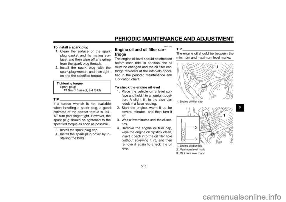
To check the en gine oil level
1. Place the vehicle on a level sur- face and hold it in an upright posi-
tion. A slight tilt to the side can
result in a false reading.
2. Start the engine, warm it up for several minutes, and then turn it
off.
3. Wait a few minutes until the oil set- tles.
4. Remove the engine oil filler cap, wipe the engine oil dipstick clean,
insert it back into the oil filler hole
(without screwing it in), and then
remove it again to check the oil
level.
TIPThe engine oil should be between the
minimum and maximum level marks.
Tightenin g torque:
Spark plug: 13 Nm (1.3 m·kgf, 9.4 ft·lbf)
1. Engine oil filler cap
1. Engine oil dipstick
2. Maximum level mark
3. Minimum level mark
1
1
32
U2DEE0E0.book Page 10 Friday, June 14, 2013 1:29 PM
Page 53 of 88
PERIODIC MAINTENANCE AND ADJUSTMENT
6-12
6
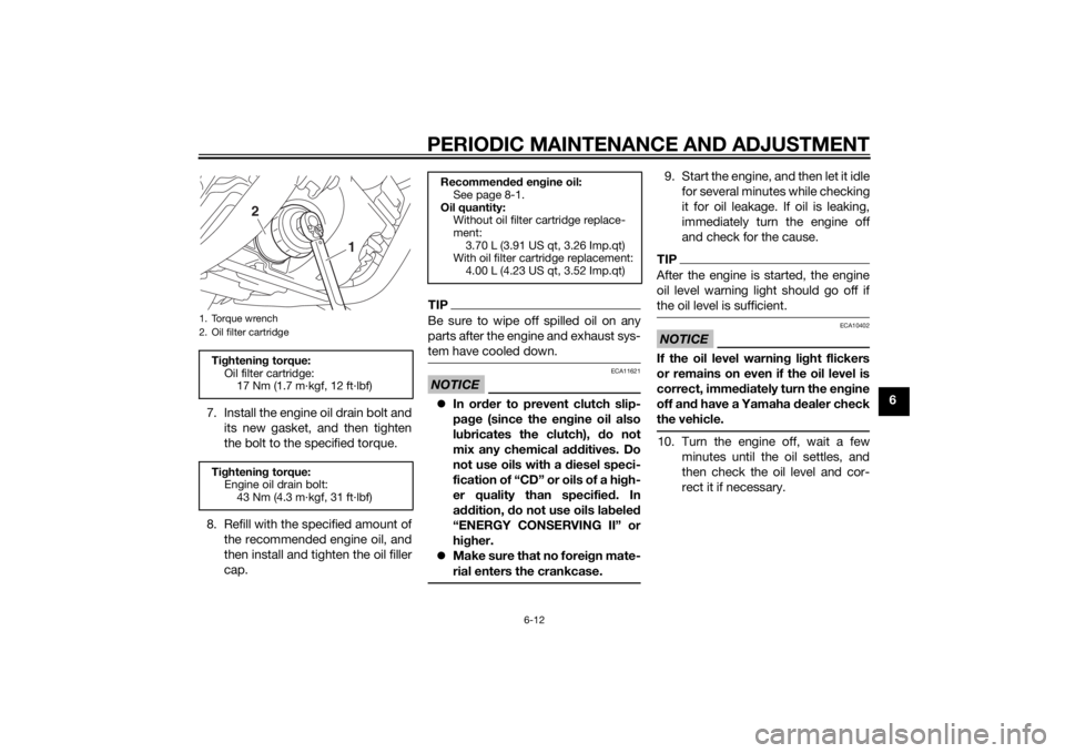
7. Install the engine oil drain bolt and
its new gasket, and then tighten
the bolt to the specified torque.
8. Refill with the specified amount of the recommended engine oil, and
then install and tighten the oil filler
cap.
TIPBe sure to wipe off spilled oil on any
parts after the engine and exhaust sys-
tem have cooled down.NOTICE
ECA11621
In or der to prevent clutch slip-
pa ge (since the en gine oil also
lu bricates the clutch), do not
mix any chemical add itives. Do
not use oils with a diesel speci-
fication of “CD” or oils of a hi gh-
er quality than specified . In
a dd ition, do not use oils lab eled
“ENERGY CONSERVING II” or
hi gher.
Make sure that no forei gn mate-
rial enters the crankcase.
9. Start the engine, and then let it idle for several minutes while checking
it for oil leakage. If oil is leaking,
immediately turn the engine off
and check for the cause.TIPAfter the engine is started, the engine
oil level warning light should go off if
the oil level is sufficient.NOTICE
ECA10402
If the oil level warnin g li ght flickers
or remains on even if the oil level is
correct, imme diately turn the en gine
off an d have a Yamaha dealer check
the vehicle.10. Turn the engine off, wait a few minutes until the oil settles, and
then check the oil level and cor-
rect it if necessary.
1. Torque wrench
2. Oil filter cartridgeTightenin g torque:
Oil filter cartridge: 17 Nm (1.7 m·kgf, 12 ft·lbf)
Ti ghtenin g torque:
Engine oil drain bolt: 43 Nm (4.3 m·kgf, 31 ft·lbf)
1
2
Recommen ded en gine oil:
See page 8-1.
Oil quantity: Without oil filter cartridge replace-
ment:3.70 L (3.91 US qt, 3.26 Imp.qt)
With oil filter cartridge replacement:
4.00 L (4.23 US qt, 3.52 Imp.qt)
U2DEE0E0.book Page 12 Friday, June 14, 2013 1:29 PM
Page 61 of 88
PERIODIC MAINTENANCE AND ADJUSTMENT
6-20
6
Use only the specifie d b rake flu-
i d ; otherwise, the ru bber seals
may deteriorate, causin g leak-
a g e.
Refill with the same type of
brake flui d. A ddin g a brake flui d
other than DOT 4 may result in a
harmful chemical reaction.
Be careful that water or dust
d oes not enter the brake flui d
reservoir when refillin g. Water
will si gnificantly lower the boil-
in g point of the flui d an d may re-
sult in vapor lock, an d d irt may
clo g the ABS hy draulic unit
valves.
NOTICE
ECA17641
Brake flui d may d amage painte d
surfaces or plastic parts. Always
clean up spille d flui d imme diately.As the brake pads wear, it is normal for
the brake fluid level to gradually go
down. A low brake fluid level may indi-
cate worn brake pads and/or brake
system leakage; therefore, be sure to
check the brake pads for wear and the
brake system for leakage. If the brake fluid level goes down suddenly, have a
Yamaha dealer check the cause before
further riding.
EAU22733
Chan
gin g the brake flui dHave a Yamaha dealer change the
brake fluid at the intervals specified in
the periodic maintenance and lubrica-
tion chart. In addition, have the oil seals
of the master cylinders and calipers as
well as the brake hoses replaced at the
intervals listed below or whenever they
are damaged or leaking.
Oil seals: Replace every two
years.
Brake hoses: Replace every four
years.
U2DEE0E0.book Page 20 Friday, June 14, 2013 1:29 PM
Page 65 of 88
PERIODIC MAINTENANCE AND ADJUSTMENT
6-24
6
EAUM1653
Lubricatin g the swin garm piv-
otsThe swingarm pivots must be lubricat-
ed by a Yamaha dealer at the intervals
specified in the periodic maintenance
and lubrication chart.
EAU23273
Checkin g the front forkThe condition and operation of the
front fork must be checked as follows
at the intervals specified in the periodic
maintenance and lubrication chart.
To check the con dition
Check the inner tubes for scratches,
damage and excessive oil leakage.
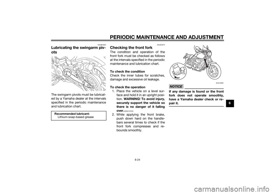
To check the operation 1. Place the vehicle on a level sur- face and hold it in an upright posi-
tion. WARNING! To avoi d injury,
securely support the vehicle so
there is no dan ger of it fallin g
over.
[EWA10752]
2. While applying the front brake, push down hard on the handle-
bars several times to check if the
front fork compresses and re-
bounds smoothly.
NOTICE
ECA10591
If any damag e is foun d or the front
fork does not operate smoothly,
have a Yamaha dealer check or re-
pair it.
Recommen ded lu bricant:
Lithium-soap-based grease
U2DEE0E0.book Page 24 Friday, June 14, 2013 1:29 PM
Page 70 of 88
![YAMAHA XV950 2014 Owners Manual PERIODIC MAINTENANCE AND ADJUSTMENT
6-29
6avoi
d causin g extensive d am-
a g e to the electrical system an d
possi bly a fire.
[EWA15132]
3. Turn the key to “ON” and turn on
the electrical circu YAMAHA XV950 2014 Owners Manual PERIODIC MAINTENANCE AND ADJUSTMENT
6-29
6avoi
d causin g extensive d am-
a g e to the electrical system an d
possi bly a fire.
[EWA15132]
3. Turn the key to “ON” and turn on
the electrical circu](/img/51/53333/w960_53333-69.png)
PERIODIC MAINTENANCE AND ADJUSTMENT
6-29
6avoi
d causin g extensive d am-
a g e to the electrical system an d
possi bly a fire.
[EWA15132]
3. Turn the key to “ON” and turn on
the electrical circuit in question to
check if the device operates.
4. If the fuse immediately blows again, have a Yamaha dealer
check the electrical system.
EAU48514
Replacin g the hea dlig ht bul bThis model is equipped with a halogen
bulb headlight. If the headlight bulb
burns out, replace it as follows.NOTICE
ECA10651
Take care not to damag e the follow-
in g parts:
Hea dlig ht bul b
Do not touch the glass part of
the hea dlig ht bul b to keep it free
from oil, otherwise the transpar-
ency of the glass, the luminosity
of the b ulb, an d the bul b life will
b e ad versely affected . Thor-
ou ghly clean off any dirt an d fin-
g erprints on the head lig ht bul b
usin g a cloth moistene d with al-
cohol or thinner.
Hea dlig ht lens
Do not affix any type of tinted
film or stickers to the hea dlig ht
lens.
Do not use a hea dlig ht bul b of a
wattag e higher than specifie d.
1. Remove the headlight unit by re-
moving the screws.
2. Disconnect the headlight coupler, and then remove the headlight
bulb cover.
Specifie d fuses:
Main fuse: 40.0 A
Headlight fuse:
20.0 A
Signaling system fuse: 7.5 A
Ignition fuse: 15.0 A
Parking lighting fuse:
15.0 A
Fuel injection system fuse: 10.0 A
ABS motor fuse: For ABS models 30.0 A
ABS solenoid fuse:
For ABS models 15.0 A
ABS control unit fuse: For ABS models 7.5 A
Backup fuse: 7.5 A
1. Do not touch the glass part of the bulb.
1. Screw
1
U2DEE0E0.book Page 29 Friday, June 14, 2013 1:29 PM