fuse YAMAHA XVS1100 2000 Owners Manual
[x] Cancel search | Manufacturer: YAMAHA, Model Year: 2000, Model line: XVS1100, Model: YAMAHA XVS1100 2000Pages: 96, PDF Size: 13.11 MB
Page 12 of 96
2-1
2
EAU00026
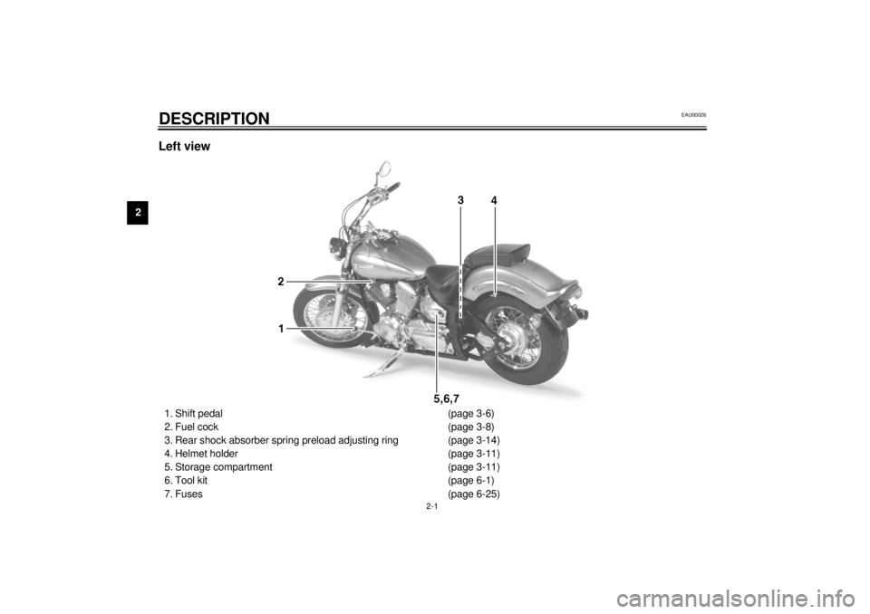
2-DESCRIPTIONLeft view1. Shift pedal (page 3-6)
2. Fuel cock (page 3-8)
3. Rear shock absorber spring preload adjusting ring (page 3-14)
4. Helmet holder (page 3-11)
5. Storage compartment (page 3-11)
6. Tool kit (page 6-1)
7. Fuses (page 6-25)
E_5el_Description.fm Page 1 Monday, May 1, 2000 9:37 AM
Page 13 of 96
DESCRIPTION
2-2
2
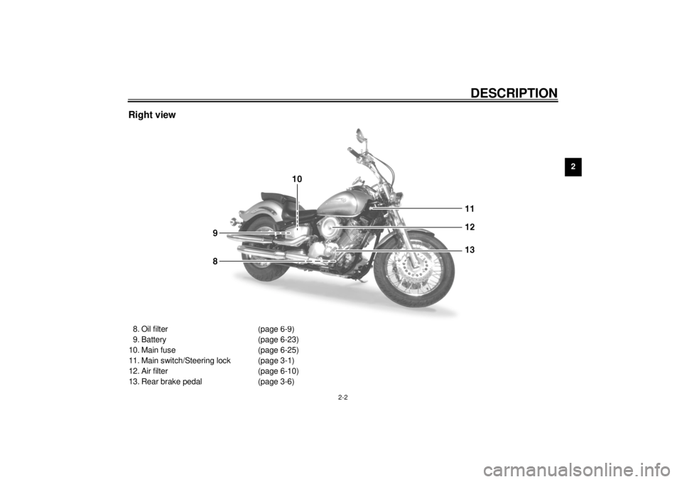
Right view8. Oil filter (page 6-9)
9. Battery (page 6-23)
10. Main fuse (page 6-25)
11. Main switch/Steering lock (page 3-1)
12. Air filter (page 6-10)
13. Rear brake pedal (page 3-6)
E_5el_Description.fm Page 2 Monday, May 1, 2000 9:37 AM
Page 45 of 96
6
PERIODIC MAINTENANCE AND MINOR REPAIR
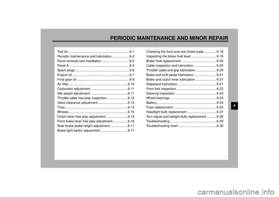
Tool kit................................................................... 6-1
Periodic maintenance and lubrication ................... 6-2
Panel removal and installation .............................. 6-5
Panel A ................................................................. 6-5
Spark plugs........................................................... 6-6
Engine oil .............................................................. 6-7
Final gear oil ......................................................... 6-9
Air filter ............................................................... 6-10
Carburetor adjustment ........................................ 6-11
Idle speed adjustment ........................................ 6-11
Throttle cable free play inspection ...................... 6-12
Valve clearance adjustment ................................ 6-12
Tires .................................................................... 6-13
Wheels ................................................................ 6-15
Clutch lever free play adjustment........................ 6-15
Front brake lever free play adjustment ................ 6-16
Rear brake pedal height adjustment ................... 6-17
Brake light switch adjustment ............................. 6-17Checking the front and rear brake pads ............. 6-18
Inspecting the brake fluid level ........................... 6-19
Brake fluid replacement ..................................... 6-20
Cable inspection and lubrication ........................ 6-20
Throttle cable and grip lubrication ...................... 6-20
Brake and shift pedal lubrication ........................ 6-21
Brake and clutch lever lubrication ...................... 6-21
Sidestand lubrication.......................................... 6-21
Front fork inspection ........................................... 6-22
Steering inspection ............................................ 6-22
Wheel bearings .................................................. 6-23
Battery................................................................ 6-23
Fuse replacement .............................................. 6-25
Headlight bulb replacement ............................... 6-27
Turn signal and taillight bulb replacement .......... 6-28
Troubleshooting .................................................. 6-29
Troubleshooting chart ......................................... 6-30
E_5el_PeriodicTOC.fm Page 1 Monday, May 1, 2000 9:43 AM
Page 70 of 96

PERIODIC MAINTENANCE AND MINOR REPAIR
6-25
6
EAU01711
Fuse replacementSub fuse box
The sub fuse box is located behind the
storage compartment cover. (See page
3-11 for removal and installation proce-
dures.)Main fuse
The main fuse is located under the rid-
er seat.
1. Remove the rider seat. (See page
3-10 for removal and installation
procedures.)2. Remove each quick fastener by
pushing the center in with a screw-
driver, then pulling the fastener
out.1. Odometer fuse
2. Ignition fuse
3. Headlight fuse
4. Carburetor heater fuse
5. Spare fuse (´ 2)
6. Signaling system fuse
Specified fuses:
Odometer fuse: 5 A
Ignition fuse: 10 A
Headlight fuse: 15 A
Carburetor heater fuse: 15 A
Signaling system fuse: 10 A
1. Quick fastener (´ 3)
E_5el_Periodic.fm Page 25 Monday, May 1, 2000 9:44 AM
Page 71 of 96
PERIODIC MAINTENANCE AND MINOR REPAIR
6-26
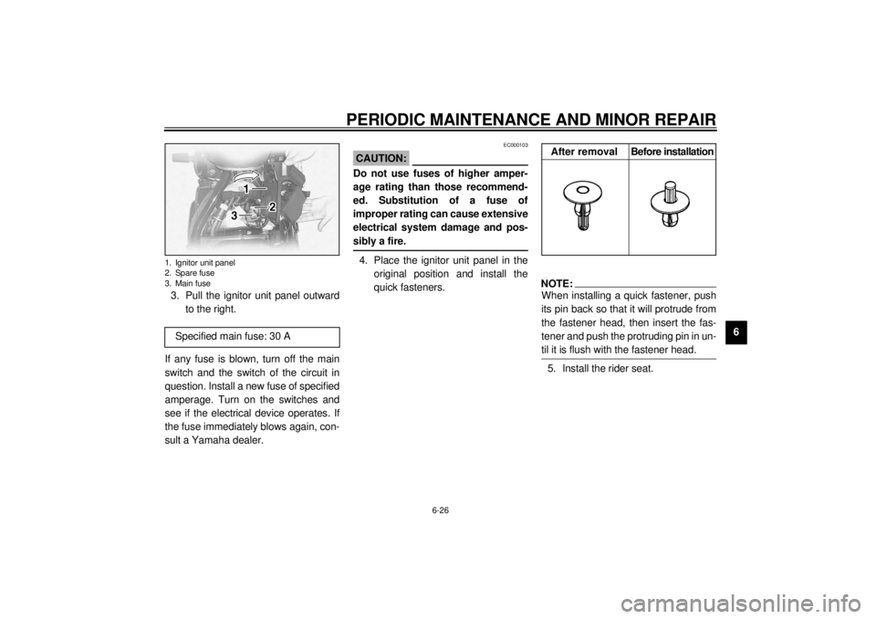
6 3. Pull the ignitor unit panel outward
to the right.
If any fuse is blown, turn off the main
switch and the switch of the circuit in
question. Install a new fuse of specified
amperage. Turn on the switches and
see if the electrical device operates. If
the fuse immediately blows again, con-
sult a Yamaha dealer.
EC000103
CAUTION:@ Do not use fuses of higher amper-
age rating than those recommend-
ed. Substitution of a fuse of
improper rating can cause extensive
electrical system damage and pos-
sibly a fire. @4. Place the ignitor unit panel in the
original position and install the
quick fasteners.
NOTE:@ When installing a quick fastener, push
its pin back so that it will protrude from
the fastener head, then insert the fas-
tener and push the protruding pin in un-
til it is flush with the fastener head. @5. Install the rider seat.
1. Ignitor unit panel
2. Spare fuse
3. Main fuse
Specified main fuse: 30 A
After removal Before installation
E_5el_Periodic.fm Page 26 Monday, May 1, 2000 9:44 AM
Page 87 of 96

SPECIFICATIONS
8-4
8
Headlight typeQuar tz bulb (halogen)
Bulb voltage, wattage ´ quantity
Headlight 12 V, 60/55 W ´ 1
Auxiliary light 12 V, 4 W ´ 1
Tail/brake light 12 V, 5/21 W ´ 1
Turn signal light 12 V, 21 W ´ 4
Meter light 14 V, 1.4 W ´ 2
Oil level indicator light 12 V, 1.7 W ´ 1
Neutral indicator light 12 V, 1.7 W ´ 1
Turn indicator light 12 V, 1.7 W ´ 1
Engine trouble indicator light 12 V, 1.7 W ´ 1
High beam indicator light 12 V, 1.7 W ´ 1
Fuses
Main fuse 30 A
Signaling system fuse 10 A
Odometer fuse 5 A
Ignition fuse 10 A
Headlight fuse 15 A
Carburetor heater fuse 15 A
E_5el_Spec.fm Page 4 Monday, May 1, 2000 9:47 AM
Page 92 of 96
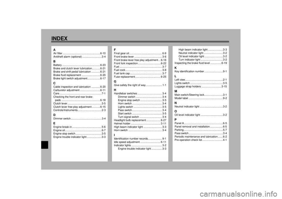
10-INDEXAAir filter .................................................. 6-10
Antitheft alarm (optional) ..........................3-4BBattery ................................................... 6-23
Brake and clutch lever lubrication........... 6-21
Brake and shift pedal lubrication ............ 6-21
Brake fluid replacement ......................... 6-20
Brake light switch adjustment ................. 6-17CCable inspection and lubrication ............ 6-20
Carburetor adjustment ........................... 6-11
Care.........................................................7-1
Checking the front and rear brake
pads .................................................... 6-18
Clutch lever ..............................................3-5
Clutch lever free play adjustment ........... 6-15
Controls/Instruments ................................2-3DDimmer switch ........................................... 3-4EEngine break-in........................................5-6
Engine oil .................................................6-7
Engine stop switch ...................................3-5
Engine trouble indicator light ....................3-3
FFinal gear oil ............................................ 6-9
Front brake lever ..................................... 3-6
Front brake lever free play adjustment ... 6-16
Front fork inspection .............................. 6-22
Fuel ......................................................... 3-7
Fuel cock ................................................. 3-8
Fuel tank cap ........................................... 3-7
Fuse replacement.................................. 6-25GGive safety the right of way ...................... 1-1HHandlebar switches ................................. 3-4
Dimmer switch ................................... 3-4
Engine stop switch ............................. 3-5
Horn switch ........................................ 3-4
Lights switch ...................................... 3-5
Pass switch ........................................ 3-4
Start switch ........................................ 3-5
Turn signal switch .............................. 3-4
Headlight bulb replacement ................... 6-27
Helmet holder ........................................ 3-11
High beam indicator light ......................... 3-3
Horn switch ............................................. 3-4IIdentification number records................... 9-1
Idle speed adjustment ........................... 6-11
Indicator lights ......................................... 3-2
Engine trouble indicator light .............. 3-3
High beam indicator light ....................3-3
Neutral indicator light ..........................3-2
Oil level indicator light .........................3-2
Turn indicator light ..............................3-2
Inspecting the brake fluid level ...............6-19
KKey identification number .........................9-1LLeft view...................................................2-1
Lights switch ............................................3-5
Luggage strap holders ...........................3-15MMain switch/Steering lock .........................3-1
Model label ..............................................9-2NNeutral indicator light ...............................3-2OOil level indicator light ..............................3-2PPanel A ....................................................6-5
Panel removal and installation..................6-5
Parking.....................................................5-7
Pass switch ..............................................3-4
Periodic maintenance and lubrication .......6-2
Pre-operation check list ............................4-1
E_5elIX.fm Page 1 Monday, May 1, 2000 9:48 AM