check engine light YAMAHA XVS125 2000 Owners Manual
[x] Cancel search | Manufacturer: YAMAHA, Model Year: 2000, Model line: XVS125, Model: YAMAHA XVS125 2000Pages: 86, PDF Size: 3.07 MB
Page 7 of 86
EAU00009
TABLE OF CONTENTS
GIVE SAFETY THE RIGHT OF WAY ..................1-1
DESCRIPTION ....................................................2-1
Left view .............................................................2-1
Right view ..........................................................2-2
Controls and Instruments ...................................2-3
INSTRUMENT AND CONTROL
FUNCTIONS ........................................................3-1
Main switch/steering lock ...................................3-1
Indicator lights ....................................................3-2
Speedometer unit ..............................................3-2
Anti-theft alarm (optional)...................................3-3
Handlebar switches............................................3-3
Clutch lever ........................................................3-5
Shift pedal ..........................................................3-5
Brake lever .........................................................3-5
Brake pedal ........................................................3-6
Fuel tank cap .....................................................3-6
Fuel ....................................................................3-7
Fuel cock............................................................3-7
Starter (choke) lever ..........................................3-8
Helmet holder.....................................................3-9
Adjusting the shock absorber assemblies..........3-9
Sidestand .........................................................3-10
Ignition circuit cut-off system............................3-10PRE-OPERATION CHECKS ...............................4-1
Pre-operation check list .....................................4-1
OPERATION AND IMPORTANT RIDING
POINTS................................................................5-1
Starting the engine .............................................5-1
Starting a warm engine ......................................5-3
Shifting ...............................................................5-3
Recommended shift points
(for Switzerland only) .......................................5-4
Tips for reducing fuel consumption ....................5-4
Engine break-in ..................................................5-4
Parking ...............................................................5-5
PERIODIC MAINTENANCE AND MINOR
REPAIR................................................................6-1
Owner’s tool kit ..................................................6-1
Periodic maintenance and lubrication chart .......6-2
Removing and installing panels .........................6-5
Checking the spark plugs...................................6-7
Engine oil and oil filter element ..........................6-9
Cleaning the air filter element ..........................6-12
Adjusting the carburetor ...................................6-14
Adjusting the engine idling speed ....................6-14
Adjusting the throttle cable free play ................6-15
Adjusting the valve clearance ..........................6-161
2
3
4
5
6
5JX-9-E0 4/9/0 4:11 AM Page 5
Page 14 of 86
3-2
INSTRUMENT AND CONTROL FUNCTIONS
3
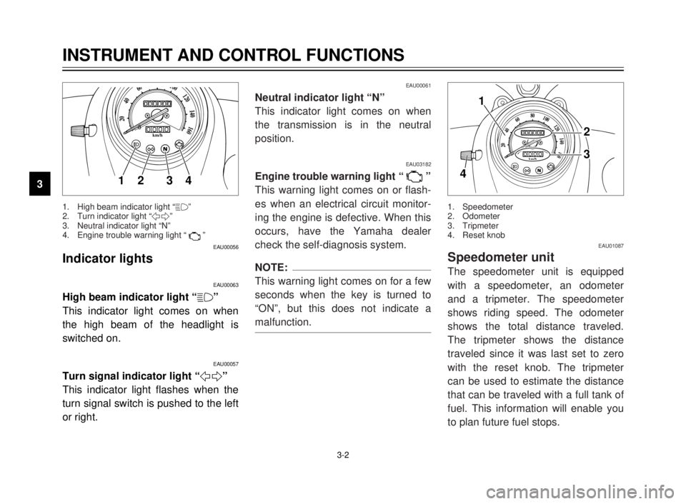
EAU00056
Indicator lights
EAU00063
High beam indicator light “&”
This indicator light comes on when
the high beam of the headlight is
switched on.
EAU00057
Turn signal indicator light “5”
This indicator light flashes when the
turn signal switch is pushed to the left
or right.
20
40
60
0km/h
80100120
140
160
12 34
EAU00061
Neutral indicator light “N”
This indicator light comes on when
the transmission is in the neutral
position.
EAU03182
Engine trouble warning light “ ”
This warning light comes on or flash-
es when an electrical circuit monitor-
ing the engine is defective. When this
occurs, have the Yamaha dealer
check the self-diagnosis system.
NOTE:
This warning light comes on for a few
seconds when the key is turned to
“ON”, but this does not indicate a
malfunction.
1. High beam indicator light “&”
2. Turn indicator light “5”
3. Neutral indicator light “N”
4. Engine trouble warning light “ ”
EAU01087
Speedometer unit
The speedometer unit is equipped
with a speedometer, an odometer
and a tripmeter. The speedometer
shows riding speed. The odometer
shows the total distance traveled.
The tripmeter shows the distance
traveled since it was last set to zero
with the reset knob. The tripmeter
can be used to estimate the distance
that can be traveled with a full tank of
fuel. This information will enable you
to plan future fuel stops.
1. Speedometer
2. Odometer
3. Tripmeter
4. Reset knob
20
40
60
0km/h
80100120
140
160
1
2
3
4
5JX-9-E0 4/9/0 4:11 AM Page 12
Page 26 of 86
5-1
EAU00372
OPERATION AND IMPORTANT RIDING POINTS
1
2
3
4
5
6
7
8
9
EAU00373
w
8Become thoroughly familiar
with all operating controls and
their functions before riding.
Consult a Yamaha dealer
regarding any control or func-
tion that you do not thorough-
ly understand.
8Never start the engine or oper-
ate it in a closed area for any
length of time. Exhaust fumes
are poisonous, and inhaling
them can cause loss of con-
sciousness and death within a
short time. Always make sure
that there is adequate ventila-
tion.
8Before starting out, make sure
that the sidestand is up. If the
sidestand is not raised com-
pletely, it could contact the
ground and distract the opera-
tor, resulting in a possible loss
of control.
EAU03237
Starting the engine
In order for the ignition circuit cut-off
system to enable starting, one of the
following conditions must be met:
8The transmission is in the neutral
position.
8The transmission is in gear with
the clutch lever pulled and the
sidestand up.
EW000054
w
8Before starting the engine,
check the function of the igni-
tion circuit cut-off system
according to the procedure
described on page 3-10.
8Never ride with the sidestand
down.
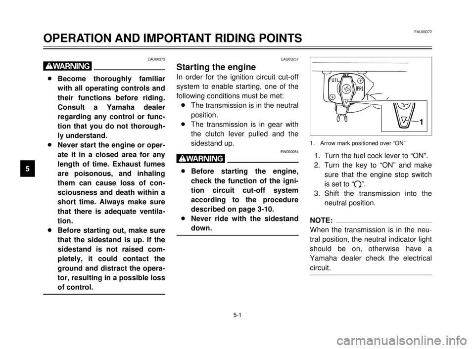
1. Turn the fuel cock lever to “ON”.
2. Turn the key to “ON” and make
sure that the engine stop switch
is set to “#”.
3. Shift the transmission into the
neutral position.
NOTE:
When the transmission is in the neu-
tral position, the neutral indicator light
should be on, otherwise have a
Yamaha dealer check the electrical
circuit.
1. Arrow mark positioned over “ON”
1
5JX-9-E0 4/9/0 4:11 AM Page 24
Page 27 of 86
OPERATION AND IMPORTANT RIDING POINTS
1
2
3
4
5
6
7
8
9
5-2
4. Turn the starter (choke) on and
completely close the throttle.
(See page 3-8 for starter (choke)
operation.)
5. Start the engine by pushing the
start switch.
NOTE:
If the engine fails to start, release the
start switch, wait a few seconds, and
then try again. Each starting attempt
should be as short as possible to pre-
serve the battery. Do not crank the
engine more than 10 seconds on any
one attempt.
ECA00059
cC
If the oil level warning light flickers
or remains on after starting, imme-
diately stop the engine, and then
check the engine oil level and the
vehicle for oil leakage. If neces-
sary, add engine oil, and then
check the warning light again. If
the warning light does not go off
after starting with sufficient engine
oil, have a Yamaha dealer check
the electrical circuit.
6. After starting the engine, move
the starter (choke) lever back
halfway.
ECA00055
cC
For maximum engine life, always
warm the engine up before starting
off. Never accelerate hard when
the engine is cold.
7. When the engine is warm, turn
the starter (choke) off.
NOTE:
The engine is warm when it responds
normally to the throttle with the starter
(choke) turned off.
5JX-9-E0 4/9/0 4:11 AM Page 25
Page 39 of 86
PERIODIC MAINTENANCE AND MINOR REPAIR
6
6-9
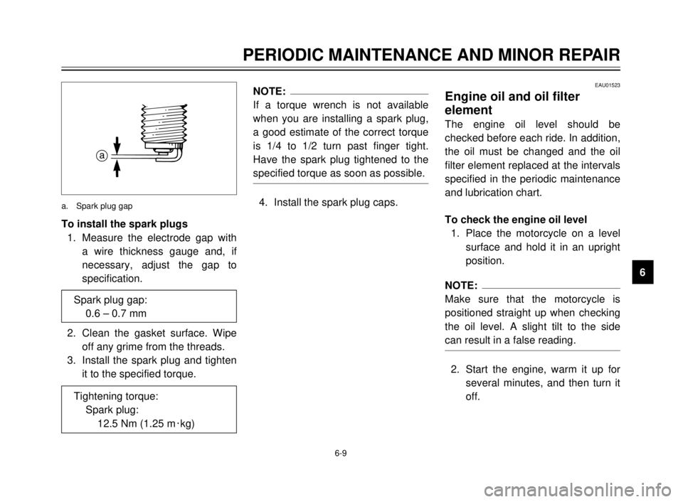
To install the spark plugs
1. Measure the electrode gap with
a wire thickness gauge and, if
necessary, adjust the gap to
specification.
2. Clean the gasket surface. Wipe
off any grime from the threads.
3. Install the spark plug and tighten
it to the specified torque.
NOTE:
If a torque wrench is not available
when you are installing a spark plug,
a good estimate of the correct torque
is 1/4 to 1/2 turn past finger tight.
Have the spark plug tightened to the
specified torque as soon as possible.
4. Install the spark plug caps.
Spark plug gap:
0.6 – 0.7 mm
Tightening torque:
Spark plug:
12.5 Nm (1.25 m0kg)
a
a. Spark plug gap
EAU01523
Engine oil and oil filter
element
The engine oil level should be
checked before each ride. In addition,
the oil must be changed and the oil
filter element replaced at the intervals
specified in the periodic maintenance
and lubrication chart.
To check the engine oil level
1. Place the motorcycle on a level
surface and hold it in an upright
position.
NOTE:
Make sure that the motorcycle is
positioned straight up when checking
the oil level. A slight tilt to the side
can result in a false reading.
2. Start the engine, warm it up for
several minutes, and then turn it
off.
5JX-9-E0 4/9/0 4:11 AM Page 37
Page 57 of 86
1
2
3
4
5
6
7
8
9
6-27
PERIODIC MAINTENANCE AND MINOR REPAIR
EAU03006
Lubricating the drive chain
The drive chain must be cleaned and
lubricated at the intervals specified in
the periodic maintenance and lubrica-
tion chart, otherwise it will quickly
wear out, especially when riding in
dusty or wet areas. Service the drive
chain as follows.
EC000097
cC
The drive chain must be lubricated
after washing the motorcycle or
riding in the rain.
1. Clean the drive chain with
kerosene and a small soft brush.
ECA00053
cC
To prevent damaging the O-rings,
do not clean the drive chain with
steam cleaners, high-pressure
washers or inappropriate solvents.
EC000096
cC
Improper drive chain slack will
overload the engine as well as
other vital parts of the motorcycle
and can lead to chain slippage or
breakage. To prevent this from
occurring, keep the drive chain
slack within the specified limits.
3. Tighten both locknuts, and then
tighten the axle nut to the speci-
fied torque.
4. Adjust the brake pedal free play.
(See page 6-22 for brake pedal
free play adjustment proce-
dures.)
EW000103
w
After adjusting the brake pedal
free play, check the operation of
the brake light.
Tightening torque:
Axle nut:
104 Nm (10.4 m·kg)
2. Wipe the drive chain dry.
3. Thoroughly lubricate the drive
chain with a special O-ring chain
lubricant.
ECA00052
cC
Do not use engine oil or any other
lubricants for the drive chain, as
they may contain substances that
could damage the O-rings.
5JX-9-E0 4/9/0 4:11 AM Page 55