clock YAMAHA XVS125 2000 Owners Manual
[x] Cancel search | Manufacturer: YAMAHA, Model Year: 2000, Model line: XVS125, Model: YAMAHA XVS125 2000Pages: 86, PDF Size: 3.07 MB
Page 18 of 86

3-6
INSTRUMENT AND CONTROL FUNCTIONS
3
EAU00162
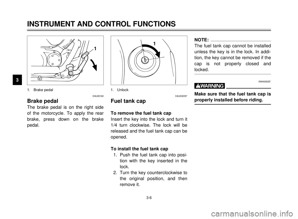
Brake pedal
The brake pedal is on the right side
of the motorcycle. To apply the rear
brake, press down on the brake
pedal.
1. Brake pedal
1
EAU03235*
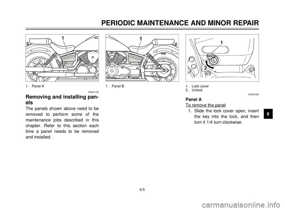
Fuel tank cap
To remove the fuel tank cap
Insert the key into the lock and turn it
1/4 turn clockwise. The lock will be
released and the fuel tank cap can be
opened.
To install the fuel tank cap
1. Push the fuel tank cap into posi-
tion with the key inserted in the
lock.
2. Turn the key counterclockwise to
the original position, and then
remove it.
1. Unlock
1NOTE:
The fuel tank cap cannot be installed
unless the key is in the lock. In addi-
tion, the key cannot be removed if the
cap is not properly closed and
locked.
EWA00025*
w
Make sure that the fuel tank cap is
properly installed before riding.
5JX-9-E0 4/9/0 4:11 AM Page 16
Page 35 of 86

PERIODIC MAINTENANCE AND MINOR REPAIR
6
6-5
1
EAU01122
Removing and installing pan-
els
The panels shown above need to be
removed to perform some of the
maintenance jobs described in this
chapter. Refer to this section each
time a panel needs to be removed
and installed.
1. Panel A
1
1. Panel B
21
EAU03184
Panel A
To remove the panel
1. Slide the lock cover open, insert
the key into the lock, and then
turn it 1/4 turn clockwise.
1. Lock cover
2. Unlock
5JX-9-E0 4/9/0 4:11 AM Page 33
Page 36 of 86

PERIODIC MAINTENANCE AND MINOR REPAIR
6
6-6
1
2. Pull the rear of the panel out with
the key inserted in the lock, and
then slide the panel forward to
release it in the front.To install the panel
1. Secure the front of the panel,
and then push the rear of the
panel in with the key inserted in
the lock.
2. Turn the key counterclockwise to
the original position, remove it,
and then close the lock cover.
EAU03185
Panel B
To remove the panel
1. Remove the bolt.
1. Bolt
5JX-9-E0 4/9/0 4:11 AM Page 34
Page 66 of 86

6-36
1
2
3
4
5
6
7
8
9
PERIODIC MAINTENANCE AND MINOR REPAIR
EAU03218
Replacing a turn signal light
bulb
1. Remove the turn signal lens by
removing the screws.
1. Screw (´2)
1
2. Remove the defective bulb by
pushing it in and turning it coun-
terclockwise.
3. Insert a new bulb into the socket,
push it in, and then turn it clock-
wise until it stops.
4. Install the lens by installing the
screws.
EC000108
cC
Do not overtighten the screws,
otherwise the lens may break.
1. Bulb
1
1
EAU01623
Replacing the tail/brake light
bulb
1. Remove the tail/brake light lens
by removing the screws.
1. Screw (´2)
5JX-9-E0 4/9/0 4:11 AM Page 64
Page 67 of 86

1
2
3
4
5
6
7
8
9
6-37
PERIODIC MAINTENANCE AND MINOR REPAIR
1
2. Remove the defective bulb by
pushing it in and turning it coun-
terclockwise.
3. Insert a new bulb into the socket,
push it in, and then turn it clock-
wise until it stops.
4. Install the lens by installing the
screws.
EC000108
cC
Do not overtighten the screws,
otherwise the lens may break.
1. Bulb
EAU01579
Supporting the motorcycle
Since this model is not equipped with
a centerstand, follow these precau-
tions when removing the front and
rear wheel or performing other main-
tenance requiring the motorcycle to
stand upright. Check that the motor-
cycle is in a stable and level position
before starting any maintenance. A
strong wooden box can be placed
under the engine for added stability.
To service the front wheel
1. Stabilize the rear of the motorcy-
cle by using a motorcycle stand
or, if an additional motorcycle
stand is not available, by placing
a jack under the frame in front of
the rear wheel.
2. Raise the front wheel off the
ground by using a motorcycle
stand.To service the rear wheel
Raise the rear wheel off the ground
by using a motorcycle stand or, if a
motorcycle stand is not available, by
placing a jack either under each side
of the frame in front of the rear wheel
or under each side of the swingarm.
5JX-9-E0 4/9/0 4:11 AM Page 65