YAMAHA XVS650A 2001 User Guide
Manufacturer: YAMAHA, Model Year: 2001, Model line: XVS650A, Model: YAMAHA XVS650A 2001Pages: 101, PDF Size: 6.77 MB
Page 11 of 101

2-1
DESCRIPTION
12
2
4
5
6
7
8
9
Left view (XVS650)
1. Shift pedal (page 3-5)
2. Fuel cock (page 3-8)
3. Starter (choke) “ ” (page 3-9)
4. Rear shock absorber spring preload adjusting ring (page 3-14)
5. Helmet holder (page 3-12)
6. Storage compartment (page 3-13)
7. Tool kit (page 6-1)
EAU00026
Page 12 of 101

2-2
DESCRIPTION
1
2
2
4
5
6
7
8
9
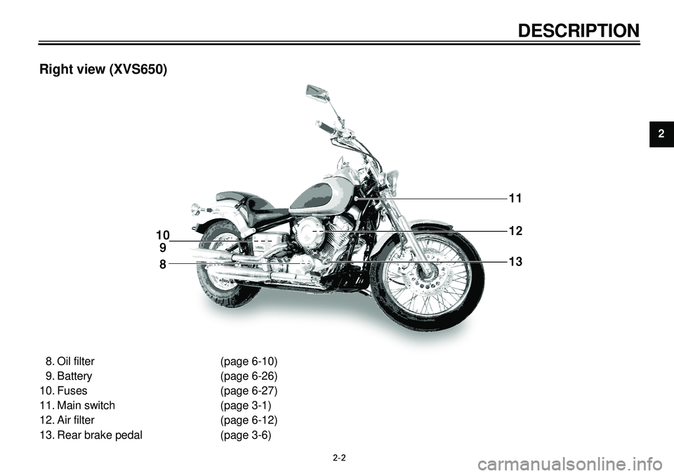
Right view (XVS650)
8. Oil filter (page 6-10)
9. Battery (page 6-26)
10. Fuses (page 6-27)
11. Main switch (page 3-1)
12. Air filter (page 6-12)
13. Rear brake pedal (page 3-6)
Page 13 of 101

2-3
DESCRIPTION
1
2
2
4
5
6
7
8
9
Left view (XVS650A)
1. Shift pedal (page 3-5)
2. Fuel cock (page 3-8)
3. Starter (choke) “ ” (page 3-9)
4. Rear shock absorber spring preload adjusting ring (page 3-14)
5. Helmet holder (page 3-12)
6. Storage compartment (page 3-13)
7. Tool kit (page 6-1)
Page 14 of 101

2-4
DESCRIPTION
1
2
2
4
5
6
7
8
9
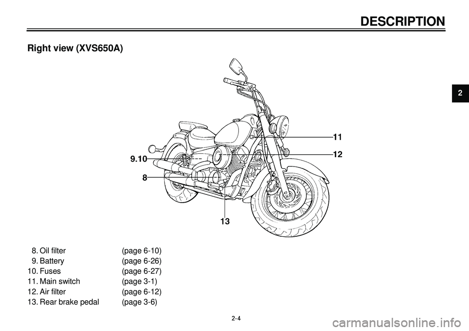
Right view (XVS650A)
8. Oil filter (page 6-10)
9. Battery (page 6-26)
10. Fuses (page 6-27)
11. Main switch (page 3-1)
12. Air filter (page 6-12)
13. Rear brake pedal (page 3-6)
Page 15 of 101

2-5
DESCRIPTION
1
2
2
4
5
6
7
8
9
Controls/Instruments (XVS650/XVS650A)
14. Clutch lever (page 3-5)
15. Left handlebar switches (page 3-3)
16. Speedometer (page 3-2)
17. Fuel tank cap (page 3-6)
18. Right handlebar switches (page 3-4)
19. Throttle grip (page 6-15)
20. Front brake lever (page 3-5)
Page 16 of 101

Main switch/Steering lock................................................................... 3-1
Indicator lights .................................................................................... 3-2
Speedometer ..................................................................................... 3-2
Antitheft alarm (optional) .................................................................... 3-3
Handlebar switches ............................................................................ 3-3
Clutch lever ........................................................................................ 3-5
Shift pedal .......................................................................................... 3-5
Front brake lever ................................................................................ 3-5
Rear brake pedal................................................................................ 3-6
Fuel tank cap ..................................................................................... 3-6
Fuel .................................................................................................... 3-7
Fuel tank breather hose ..................................................................... 3-7
Fuel cock ............................................................................................ 3-8
Starter (choke) “ ” .......................................................................... 3-9
Seats (for XVS650) ............................................................................ 3-9
Seats (for XVS650A) ........................................................................ 3-11
Helmet holder................................................................................... 3-12
Storage compartment ...................................................................... 3-13
Rear shock absorber adjustment ..................................................... 3-14
Luggage strap holders ..................................................................... 3-15
Sidestand ......................................................................................... 3-15
Sidestand/clutch switch operation check ......................................... 3-16
INSTRUMENT AND CONTROL FUNCTIONS
3
Page 17 of 101

3-1
INSTRUMENT AND CONTROL FUNCTIONS
1
23
4
5
6
7
8
9
EAU00029
Main switch/Steering lock
The main switch controls the ignition
and lighting systems. Its operation is
described below.
EAU00036
ON
Electrical circuits are switched on. The
engine can be started. The key cannot
be removed in this position.
EAU00038
OFF
All electrical circuits are switched off.
The key can be removed in this posi-
tion.
EAU00040
LOCK
The steering is locked in this position
and all electrical circuits are switched off.
The key can be removed in this posi-
tion. To lock the steering, turn the han-
dlebars all the way to the left. While
pushing the key into the main switch,
turn it from “OFF” to “LOCK” and re-
move it. To release the lock, turn the
key to “OFF” while pushing.
EW000016
WARNING
Never turn the key to “OFF” or
“LOCK” when the motorcycle is
moving. The electrical circuits will
be switched off which may result in
loss of control or an accident. Be
sure the motorcycle is stopped be-
fore turning the key to “OFF” or
“LOCK”.
1. Push
2. Turn
EAU00044
(Parking)
The steering is locked in this position
and the taillight comes on, but all other
circuits are off. The key can be re-
moved in this position.
To use the parking position, first lock
the steering, then turn the key to “ ”.
Do not use this position for an extend-
ed length of time as the battery may
discharge.
EAU00027
Page 18 of 101

3-2
INSTRUMENT AND CONTROL FUNCTIONS
1
2
3
4
5
6
7
8
9
1. High beam indicator light “ ”
2. Turn indicator light “ ”
3. Neutral indicator light “ ”
4. Engine trouble indicator light “ ”
EAU00056
Indicator lights
EAU00057
1. Turn indicator light “ ”
This indicator flashes when the turn
switch is moved to the left or right.
EAU00061
2. Neutral indicator light “ ”
This indicator comes on when the
transmission is in neutral.
EAU00063
3. High beam indicator light “ ”
This indicator comes on when the
headlight high beam is used.
EAU00091
4. Engine trouble indicator light
“”
This indicator light will come on or flash
if trouble occurs in a monitoring circuit.
In such a case, take the motorcycle to
a Yamaha dealer to have the self-diag-
nostic systems checked.
1. Reset knob
2. Speedometer
3. Odometer
4. Trip odometer
EAU00095
Speedometer
The speedometer shows riding speed.
This speedometer is equipped with an
odometer and trip odometer. The trip
odometer can be reset to “0” with the
reset knob. Use the trip odometer to
estimate how far you can ride on a
tank of fuel. This information will en-
able you to plan fuel stops in the fu-
ture.
Page 19 of 101

3-3
INSTRUMENT AND CONTROL FUNCTIONS
1
2
3
4
5
6
7
8
9
EAU00109
Antitheft alarm (optional)
An antitheft alarm can be equipped to
this motorcycle. Consult your Yamaha
dealer to obtain and install the alarm.
1. Turn signal switch
2. Pass switch “ ”
3. Dimmer switch
4. Horn switch “ ”
EAU00118
Handlebar switches
EAU00127
Turn signal switch
To signal a right-hand turn, push the
switch to “ ”. To signal a left-hand
turn, push the switch to “ ”. Once
the switch is released it will return to
the center position. To cancel the sig-
nal, push the switch in after it has re-
turned to the center position.
EAU00119
Pass switch “ ”
Press the switch to operate the pass-
ing light.
EAU00121
Dimmer switch
Turn the switch to “ ” for the high
beam and to “ ” for the low beam.
EAU00129
Horn switch “ ”
Press the switch to sound the horn.
Page 20 of 101

3-4
INSTRUMENT AND CONTROL FUNCTIONS
1
2
3
4
5
6
7
8
9
1. Start switch “ ”
2. Engine stop switch
3. Lights switch
EAU00143
Start switch “ ”
The starter motor cranks the engine
when pushing the start switch.
EC000005
CAUTION:
See starting instructions prior to
starting the engine.
EAU00138
Engine stop switch
The engine stop switch is a safety de-
vice for use in an emergency such as
when the motorcycle overturns or if
trouble occurs in the throttle system.
Turn the switch to “ ” to start the en-
gine. In case of emergency, turn the
switch to “ ” to stop the engine.
EAU00134
Lights switch
Turning the light switch to “ ”,
turns on the auxiliary light, meter lights
and taillight. Turning the light switch to
“ ”, turns the headlight on also.