clock YAMAHA XVS650A 2005 Owners Manual
[x] Cancel search | Manufacturer: YAMAHA, Model Year: 2005, Model line: XVS650A, Model: YAMAHA XVS650A 2005Pages: 86, PDF Size: 10.89 MB
Page 22 of 86

INSTRUMENT AND CONTROL FUNCTIONS
3-8
3
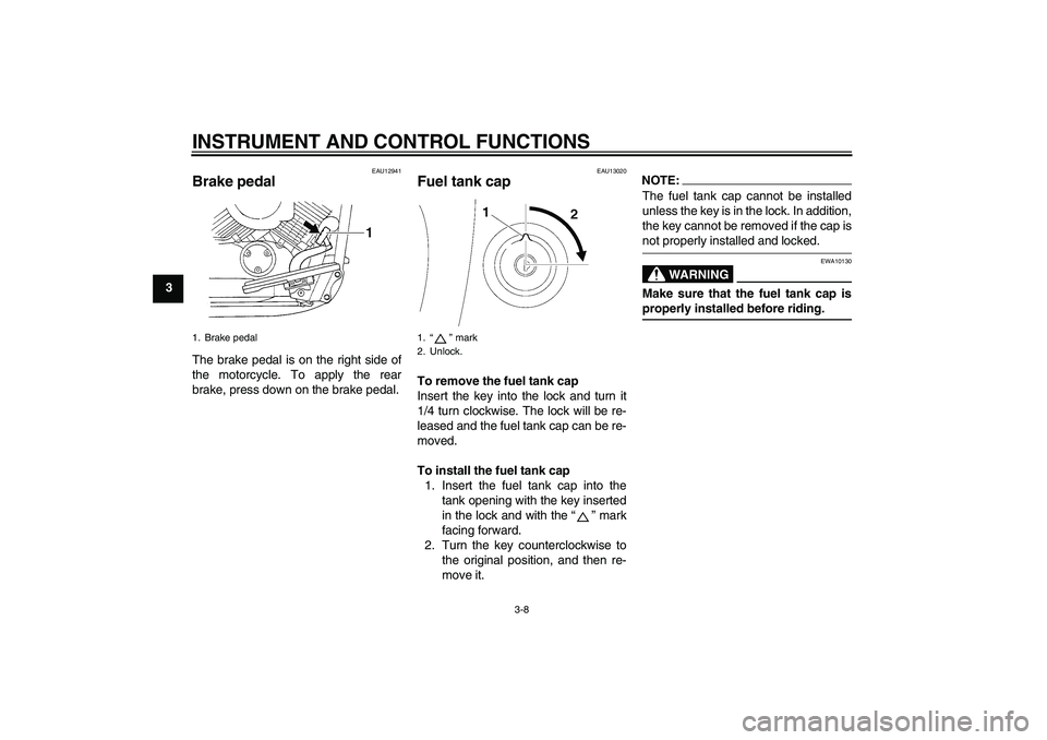
EAU12941
Brake pedal The brake pedal is on the right side of
the motorcycle. To apply the rear
brake, press down on the brake pedal.
EAU13020
Fuel tank cap To remove the fuel tank cap
Insert the key into the lock and turn it
1/4 turn clockwise. The lock will be re-
leased and the fuel tank cap can be re-
moved.
To install the fuel tank cap
1. Insert the fuel tank cap into the
tank opening with the key inserted
in the lock and with the “” mark
facing forward.
2. Turn the key counterclockwise to
the original position, and then re-
move it.
NOTE:The fuel tank cap cannot be installed
unless the key is in the lock. In addition,
the key cannot be removed if the cap isnot properly installed and locked.
WARNING
EWA10130
Make sure that the fuel tank cap isproperly installed before riding.
1. Brake pedal
1.“” mark
2. Unlock.
U5SCERE0.book Page 8 Saturday, March 12, 2005 2:08 PM
Page 27 of 86

INSTRUMENT AND CONTROL FUNCTIONS
3-13
3
EAU14281
Helmet holder To open the helmet holder, insert the
key into the lock, and then turn the key
as shown.
To lock the helmet holder, place it in the
original position, and then remove the
key.
WARNING
EWA10160
Never ride with a helmet attached to
the helmet holder, since the helmet
may hit objects, causing loss of con-trol and possibly an accident.
EAU14481
Storage compartment The storage compartment is located on
the left side of the vehicle.
To open the storage compartment
1. Slide the lock cover open, insert
the key into the lock, and then turn
it clockwise.
2. Pull the storage compartment cov-
er out as shown.To close the storage compartment
1. Place the storage compartment
cover in its original position as
shown.
2. Turn the key counterclockwise, re-
move it, and then close the lock
cover.
1. Helmet holder
2. Unlock.
1. Storage compartment cover
2. Storage compartment lock cover
3. Storage compartment lock
1. Storage compartment
2. Storage compartment cover
U5SCERE0.book Page 13 Saturday, March 12, 2005 2:08 PM
Page 66 of 86

PERIODIC MAINTENANCE AND MINOR REPAIR
6-28
6
CAUTION:
ECA10640
Do not use a fuse of a higher amper-
age rating than recommended to
avoid causing extensive damage to
the electrical system and possibly afire.
3. Turn the key to “ON” and turn on
the electrical circuit in question to
check if the device operates.
4. If the fuse immediately blows
again, have a Yamaha dealer
check the electrical system.
EAU23780
Replacing the headlight bulb This model is equipped with a quartz
bulb headlight. If the headlight bulb
burns out, replace it as follows.
1. Remove the headlight unit by re-
moving the screws.
2. Disconnect the headlight coupler,
and then remove the bulb cover.3. Remove the headlight bulb holder
by turning it counterclockwise, and
then remove the defective bulb.
Specified fuses:
Main fuse:
30.0 A
Signaling system fuse:
10.0 A
Ignition fuse:
10.0 A
Headlight fuse:
15.0 A
Carburetor heater fuse:
15.0 A
Backup fuse:
10.0 A
Parking lighting fuse:
10.0 A
Ignitor unit fuse:
5.0 A
1. Screw
1. Headlight coupler
2. Headlight bulb cover
1. Headlight bulb holder
U5SCERE0.book Page 28 Saturday, March 12, 2005 2:08 PM
Page 68 of 86

PERIODIC MAINTENANCE AND MINOR REPAIR
6-30
62. Remove the defective bulb by
pushing it in and turning it counter-
clockwise.
3. Insert a new bulb into the socket,
push it in, and then turn it clock-
wise until it stops.
4. Install the lens by installing the
screws.
CAUTION:
ECA10680
Do not overtighten the screws, oth-erwise the lens may break.
EAU33411
Replacing the auxiliary light
bulb If the auxiliary light bulb burns out, re-
place it as follows.
1. Remove the headlight unit by re-
moving the screws.
2. Remove the socket (together with
the bulb) by pushing it in and turn-
ing it counterclockwise.3. Remove the defective bulb by
pushing it in and turning it counter-
clockwise.
4. Insert a new bulb into the socket,
push it in, and then turn it clock-
wise until it stops.
5. Install the socket (together with the
bulb) by pushing it in and turning it
clockwise until it stops.
6. Install the headlight unit by install-
ing the screws.1. Screw
1. Auxiliary light bulb socket
U5SCERE0.book Page 30 Saturday, March 12, 2005 2:08 PM