brake YAMAHA YBR125 2014 Owners Manual
[x] Cancel search | Manufacturer: YAMAHA, Model Year: 2014, Model line: YBR125, Model: YAMAHA YBR125 2014Pages: 84, PDF Size: 1.82 MB
Page 6 of 84

TABLE OF CONTENTSSAFETY INFORMATION.................. 1-1
DESCRIPTION .................................. 2-1
Left view ......................................... 2-1
Right view ....................................... 2-2
Controls and instruments ............... 2-3
INSTRUMENT AND CONTROL
FUNCTIONS ...................................... 3-1
Main switch/steering lock............... 3-1
Indicator lights and warning light ... 3-2
Speedometer unit ........................... 3-3
Tachometer .................................... 3-3
Self-diagnosis device ..................... 3-3
Fuel gauge ...................................... 3-4
Handlebar switches ........................ 3-4
Clutch lever .................................... 3-5
Shift pedal ...................................... 3-5
Brake lever...................................... 3-5
Brake pedal .................................... 3-6
Fuel tank cap .................................. 3-6
Fuel ................................................. 3-7
Catalytic converters........................ 3-8
Kickstarter ...................................... 3-9
Adjusting the shock absorber assemblies .................................. 3-9
Carrier ........................................... 3-10
Sidestand ..................................... 3-10
Ignition circuit cut-off system ....... 3-11 FOR YOUR SAFETY –
PRE-OPERATION CHECKS
............. 4-1
OPERATION AND IMPORTANT
RIDING POINTS ................................ 5-1
Starting the engine .......................... 5-1
Shifting ............................................ 5-2
Tips for reducing fuel consumption ................................ 5-3
Engine break-in ............................... 5-3
Parking ............................................ 5-4
PERIODIC MAINTENANCE AND
ADJUSTMENT ................................... 6-1
Owner’s tool kit ............................... 6-2
Periodic maintenance chart for the emission control system .............. 6-3
General maintenance and lubrication chart ........................... 6-4
Removing and installing panels ...... 6-7
Checking the spark plug ................. 6-8
Engine oil....................................... 6-10
Cleaning the air filter element ....... 6-11
Checking the engine idling
speed ......................................... 6-13
Checking the throttle grip free
play ............................................ 6-13
Valve clearance ............................. 6-14
Tires .............................................. 6-14
Cast wheels................................... 6-16 Adjusting the clutch lever free
play ............................................ 6-16
Checking the brake lever free play ............................................ 6-17
Adjusting the brake pedal free
play ............................................ 6-18
Checking the shift pedal ............... 6-18
Brake light switches ..................... 6-19
Checking the front brake pads and rear brake shoes ............... 6-19
Checking the brake fluid level ...... 6-20
Changing the brake fluid .............. 6-21
Drive chain slack........................... 6-21
Cleaning and lubricating the drive
chain.......................................... 6-23
Checking and lubricating the cables ........................................ 6-24
Checking and lubricating the throttle grip and cable ............... 6-24
Checking and lubricating the
brake and clutch levers ............. 6-24
Checking and lubricating the brake pedal ............................... 6-25
Checking and lubricating the centerstand and sidestand........ 6-25
Lubricating the swingarm
pivots......................................... 6-26
Checking the front fork ................. 6-26
Checking the steering................... 6-27
Checking the wheel bearings ....... 6-27
Battery .......................................... 6-28U51DE1E0.book Page 1 Thursday, August 29, 2013 4:41 PM
Page 7 of 84

TABLE OF CONTENTS
Replacing the fuse.........................6-29
Replacing the headlight bulb.........6-30
Replacing the tail/brake light bulb ............................................6-31
Replacing a turn signal light
bulb ............................................6-32
Replacing the auxiliary light bulb ...........................................6-32
Front wheel....................................6-33
Rear wheel.....................................6-35
Troubleshooting ............................6-36
Troubleshooting chart ...................6-38
MOTORCYCLE CARE AND
STORAGE ..........................................7-1
Matte color caution .........................7-1
Care .................................................7-1
Storage ............................................7-4
SPECIFICATIONS ..............................8-1
CONSUMER INFORMATION ............9-1
Identification numbers .....................9-1
INDEX ...............................................10-1
U51DE1E0.book Page 2 Thursday, August 29, 2013 4:41 PM
Page 14 of 84
DESCRIPTION
2-2
2
EAU10421
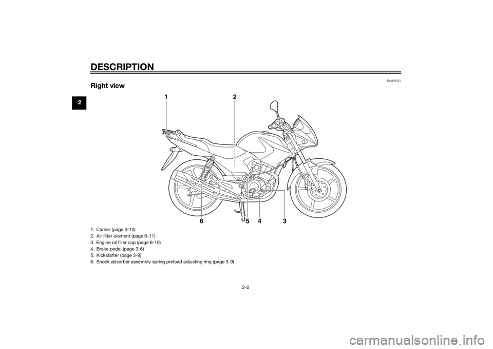
Right view
1
2
3
4
5
6
1. Carrier (page 3-10)
2. Air filter element (page 6-11)
3. Engine oil filler cap (page 6-10)
4. Brake pedal (page 3-6)
5. Kickstarter (page 3-9)
6. Shock absorber assembly spring preload adjusting ring (page 3-9)U51DE1E0.book Page 2 Thursday, August 29, 2013 4:41 PM
Page 15 of 84
DESCRIPTION
2-3
2
EAU10431
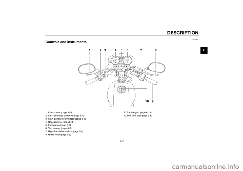
Controls and instruments
1
2
3
4
5
6
7
8
9
10
1. Clutch lever (page 3-5)
2. Left handlebar switches (page 3-4)
3. Main switch/steering lock (page 3-1)
4. Speedometer (page 3-3)
5. Fuel gauge (page 3-4)
6. Tachometer (page 3-3)
7. Right handlebar switch (page 3-4)
8. Brake lever (page 3-5) 9. Throttle grip (page 6-13)
10.Fuel tank cap (page 3-6)
U51DE1E0.book Page 3 Thursday, August 29, 2013 4:41 PM
Page 20 of 84
INSTRUMENT AND CONTROL FUNCTIONS
3-5
3
EAU12821
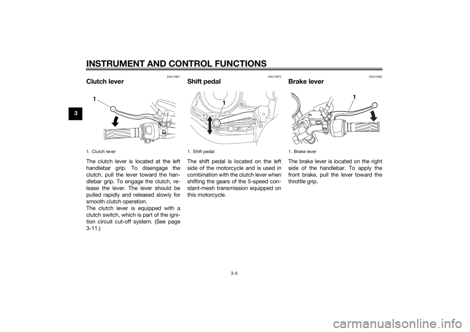
Clutch leverThe clutch lever is located at the left
handlebar grip. To disengage the
clutch, pull the lever toward the han-
dlebar grip. To engage the clutch, re-
lease the lever. The lever should be
pulled rapidly and released slowly for
smooth clutch operation.
The clutch lever is equipped with a
clutch switch, which is part of the igni-
tion circuit cut-off system. (See page
3-11.)
EAU12872
Shift pedalThe shift pedal is located on the left
side of the motorcycle and is used in
combination with the clutch lever when
shifting the gears of the 5-speed con-
stant-mesh transmission equipped on
this motorcycle.
EAU12892
Brake leverThe brake lever is located on the right
side of the handlebar. To apply the
front brake, pull the lever toward the
throttle grip.
1. Clutch lever
1. Shift pedal
1
1. Brake lever
1
U51DE1E0.book Page 5 Thursday, August 29, 2013 4:41 PM
Page 21 of 84
INSTRUMENT AND CONTROL FUNCTIONS
3-6
3
EAU12942
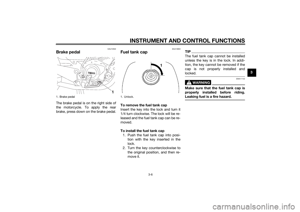
Brake pedalThe brake pedal is on the right side of
the motorcycle. To apply the rear
brake, press down on the brake pedal.
EAU13003
Fuel tank capTo remove the fuel tank cap
Insert the key into the lock and turn it
1/4 turn clockwise. The lock will be re-
leased and the fuel tank cap can be re-
moved.
To install the fuel tank cap
1. Push the fuel tank cap into posi- tion with the key inserted in the
lock.
2. Turn the key counterclockwise to the original position, and then re-
move it.
TIPThe fuel tank cap cannot be installed
unless the key is in the lock. In addi-
tion, the key cannot be removed if the
cap is not properly installed and
locked.
WARNING
EWA11142
Make sure that the fuel tank cap is
properly installe d before ri din g.
Leakin g fuel is a fire hazar d.
1. Brake pedal
1
1. Unlock.
1
U51DE1E0.book Page 6 Thursday, August 29, 2013 4:41 PM
Page 28 of 84
FOR YOUR SAFETY – PRE-OPERATION CHECKS
4-1
4
EAU15598
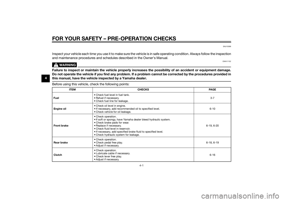
Inspect your vehicle each time you use it to make sure the vehicle is in safe operating condition. Always follow the inspection
and maintenance procedures and schedules described in the Owner’s Manual.
WARNING
EWA11152
Failure to inspect or maintain the vehicle properly increases the possibility of an acci dent or equipment damag e.
Do not operate the vehicle if you fin d any pro blem. If a pro blem cannot be corrected b y the proce dures provi ded in
this manual, have the vehicle inspecte d b y a Yamaha dealer.Before using this vehicle, check the following points:
ITEM CHECKS PAGE
Fuel • Check fuel level in fuel tank.
• Refuel if necessary.
• Check fuel line for leakage. 3-7
En gine oil • Check oil level in engine.
• If necessary, add recommended oil to specified level.
• Check vehicle for oil leakage. 6-10
Front brake • Check operation.
• If soft or spongy, have Yamaha dealer bleed hydraulic system.
• Check brake pads for wear.
• Replace if necessary.
• Check fluid level in reservoir.
• If necessary, add specified brake fluid to specified level.
• Check hydraulic system for leakage. 6-19, 6-20
Rear brake • Check operation.
• Check pedal free play.
• Adjust if necessary. 6-18, 6-19
Clutch • Check operation.
• Lubricate cable if necessary.
• Check lever free play.
• Adjust if necessary. 6-16
U51DE1E0.book Page 1 Thursday, August 29, 2013 4:41 PM
Page 29 of 84

FOR YOUR SAFETY – PRE-OPERATION CHECKS
4-2
4
Throttle grip • Make sure that operation is smooth.
• Check throttle grip free play.
• If necessary, have Yamaha dealer adjust throttle grip free play and lubricate ca-
ble and grip housing. 6-13, 6-24
Control ca bles • Make sure that operation is smooth.
• Lubricate if necessary.
6-24
Drive chain • Check chain slack.
• Adjust if necessary.
• Check chain condition.
• Lubricate if necessary. 6-21, 6-23
Wheels an d tires • Check for damage.
• Check tire condition and tread depth.
• Check air pressure.
• Correct if necessary. 6-14, 6-16
Shift pe dal • Make sure that operation is smooth.
• Correct if necessary.
6-18
Brake pe dal • Make sure that operation is smooth.
• Lubricate pedal pivoting point if necessary. 6-25
Brake an d clutch levers • Make sure that operation is smooth.
• Lubricate lever pivoting points if necessary. 6-24
Centerstan d, si destan d • Make sure that operation is smooth.
• Lubricate pivots if necessary.
6-25
Chassis fasteners • Make sure that all nuts, bolts and screws are properly tightened.
• Tighten if necessary.
—
Instruments, li ghts, si gnals
an d switches • Check operation.
• Correct if necessary.
—
Si destan d switch • Check operation of ignition circuit cut-off system.
• If system is not working correctly, have Yamaha dealer check vehicle.
3-10
ITEM CHECKS PAGE
U51DE1E0.book Page 2 Thursday, August 29, 2013 4:41 PM
Page 34 of 84
PERIODIC MAINTENANCE AND ADJUSTMENT
6-1
6
EAU17245
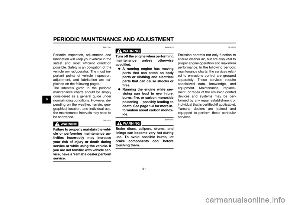
Periodic inspection, adjustment, and
lubrication will keep your vehicle in the
safest and most efficient condition
possible. Safety is an obligation of the
vehicle owner/operator. The most im-
portant points of vehicle inspection,
adjustment, and lubrication are ex-
plained on the following pages.
The intervals given in the periodic
maintenance charts should be simply
considered as a general guide under
normal riding conditions. However, de-
pending on the weather, terrain, geo-
graphical location, and individual use,
the maintenance intervals may need to
be shortened.
WARNING
EWA10322
Failure to properly maintain the vehi-
cle or performing maintenance ac-
tivities incorrectly may increase
your risk of injury or death durin g
service or while usin g the vehicle. If
you are not familiar with vehicle ser-
vice, have a Yamaha d ealer perform
service.
WARNING
EWA15123
Turn off the en gine when performin g
maintenance unless otherwise
specified .
A runnin g en gine has movin g
parts that can catch on body
parts or clothin g an d electrical
parts that can cause shocks or
fires.
Runnin g the en gine while ser-
vicin g can lead to eye injury,
b urns, fire, or car bon monoxi de
poisonin g – possi bly lea din g to
d eath. See pag e 1-3 for more in-
formation a bout car bon monox-
i d e.
WARNING
EWA15461
Brake discs, calipers, drums, and
linin gs can b ecome very hot d uring
use. To avoi d possi ble burns, let
b rake components cool before
touchin g them.
EAU17303
Emission controls not only function to
ensure cleaner air, but are also vital to
proper engine operation and maximum
performance. In the following periodic
maintenance charts, the services relat-
ed to emissions control are grouped
separately. These services require
specialized data, knowledge, and
equipment. Maintenance, replace-
ment, or repair of the emission control
devices and systems may be per-
formed by any repair establishment or
individual that is certified (if applicable).
Yamaha dealers are trained and equipped to perform these particular
services.
U51DE1E0.book Page 1 Thursday, August 29, 2013 4:41 PM
Page 37 of 84

PERIODIC MAINTENANCE AND ADJUSTMENT
6-4
6
EAU1771A
General maintenance and lu brication chartNO. ITEM CHECK OR MAINTENANCE JOB ODOMETER READING
ANNUAL
CHECK
1000 km
(600 mi) 6000 km
(3500 mi) 12000 km
(7000 mi) 18000 km
(10500 mi) 24000 km
(14000 mi)
1 Air filter element • Clean.
√√
•Replace. √√
2Clutch • Check operation.
•Adjust. √√√√√
3 *Front brake • Check operation, fluid level and
vehicle for fluid leakage. √√√√√√
• Replace brake pads. Whenever worn to the limit
4 *Rear brake • Check operation and adjust brake
pedal free play. √√√√√√
• Replace brake shoes. Whenever worn to the limit
5 *Brake hose • Check for cracks or damage.
• Check for correct routing and
clamping. √√√√√
• Replace. Every 4 years
6 *Brake flui d • Replace. Every 2 years
7 *Wheels • Check runout and for damage. √√√√
8 *Tires • Check tread depth and for dam-
age.
• Replace if necessary.
• Check air pressure.
• Correct if necessary. √√√√√
9 *Wheel bearin gs • Check bearing for looseness or
damage. √√√√
U51DE1E0.book Page 4 Thursday, August 29, 2013 4:41 PM