oil temperature YAMAHA YFM700R 2016 Owners Manual
[x] Cancel search | Manufacturer: YAMAHA, Model Year: 2016, Model line: YFM700R, Model: YAMAHA YFM700R 2016Pages: 160, PDF Size: 3.75 MB
Page 105 of 160

8-13
8
EBU26788Engine oil and oil filter elementThe engine oil level should be checked before
each ride. In addition, the oil must be changed and
the oil filter element replaced at the intervals spec-
ified in the periodic maintenance and lubrication
chart.
To check the engine oil level1. Place the ATV on a level surface.
2. Start the engine, warm it up until the engine oil has reached a normal temperature of 60
°C (140 °F), let it continue to idle for ten sec-
onds or more, and then turn the engine off.TIPTo achieve the proper engine oil temperature for
an accurate oil level reading, the engine must have
first completely cooled down, and then warmed
up again for several minutes to normal operating
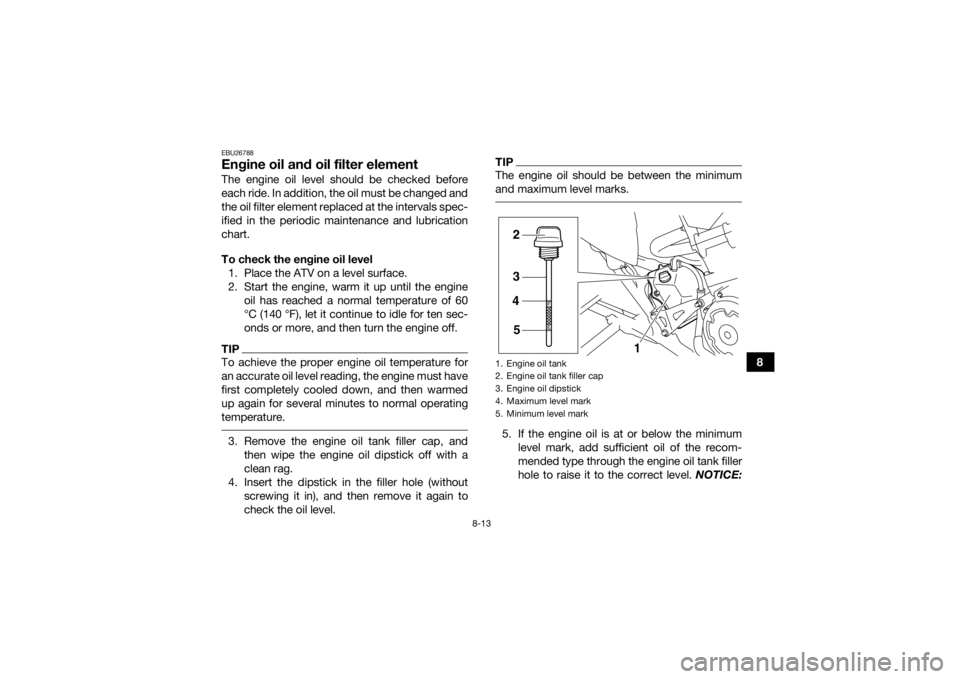
temperature. 3. Remove the engine oil tank filler cap, andthen wipe the engine oil dipstick off with a
clean rag.
4. Insert the dipstick in the filler hole (without screwing it in), and then remove it again to
check the oil level.
TIPThe engine oil should be between the minimum
and maximum level marks. 5. If the engine oil is at or below the minimumlevel mark, add sufficient oil of the recom-
mended type through the engine oil tank filler
hole to raise it to the correct level. NOTICE:1. Engine oil tank
2. Engine oil tank filler cap
3. Engine oil dipstick
4. Maximum level mark
5. Minimum level mark
2
3
4
5 1
U2LS61E0.book Page 13 Friday, April 17, 2015 8:25 AM
Page 154 of 160

10-4
10
Rim size:9 x 8.0ATFront brake:Type:
Disc brake
Operation: Right hand operation
Specified brake fluid: DOT 4Rear brake:Type:Disc brake
Operation: Right foot operation
Specified brake fluid:
DOT 4Front suspension:Type:Double wishbone
Spring/shock absorber type:
Coil spring/gas-oil damper
Wheel travel: 230 mm (9.1 in)Rear suspension:Type:
Swingarm (link suspension)
Spring/shock absorber type: Coil spring/gas-oil damper
Wheel travel: 256 mm (10.1 in)
Electrical system:Ignition system:TCI
Charging system:
AC magnetoBattery:Model:GT9B-4
Voltage, capacity:
12 V, 8.0 AhHeadlight:Bulb type:Krypton bulbBulb voltage, wattage × quantity:Headlight:
12 V, 30.0/30.0 W × 2
Tail/brake light: LED
Neutral indicator light:
LED
Fuel level warning light: LED
Reverse indicator light: LED
Coolant temperature warning light:
LED
Engine trouble warning light: LEDFuses:Main fuse:
30.0 A
U2LS61E0.book Page 4 Friday, April 17, 2015 8:25 AM
Page 158 of 160

12-1
12
INDEX
AAccessories and loading ................................................ 6-7
Air filter element, cleaning ............................................ 8-21BBattery .......................................................................... 8-45
Brake and clutch levers, checking and lubricating ...... 8-41
Brake fluid, changing ...................................................8-33
Brake fluid level, checking ........................................... 8-31
Brake lever ..................................................................... 4-6
Brake lever free play, checking the front ..................... 8-33
Brake light switches ..................................................... 8-36
Brake pads, checking the front and rear ..................... 8-29
Brake pedal .................................................................... 4-7
Brake pedal, checking and lubricating ........................ 8-41
Brake pedal height, checking ...................................... 8-34
Brakes .......................................................................... 8-29
Brakes, front and rear .................................................... 5-4CCables, checking and lubricating ................................. 8-40
Chassis fasteners ........................................................... 5-7
Cleaning ......................................................................... 9-1
Clutch lever .................................................................... 4-6
Clutch lever free play, adjusting ................................... 8-36
Coolant ................................................................. 5-4, 8-17
Coolant temperature warning light ................................. 4-2DDrive chain ..................................................................... 5-5
Drive chain, lubricating ................................................ 8-40
Drive chain slack .......................................................... 8-38
EEngine break-in .............................................................. 6-5
Engine idling speed ...................................................... 8-27
Engine oil ....................................................................... 5-4
Engine oil and oil filter element .................................... 8-13
Engine, start ................................................................... 6-1
Engine stop switch ......................................................... 4-4
Engine trouble warning light .......................................... 4-3FFuel ...................................................................... 4-10, 5-4
Fuel level warning light ................................................... 4-3
Fuel tank cap ............................................................... 4-10
Fuses, replacing ........................................................... 8-48HHandlebar switches ....................................................... 4-4
Headlight beam, adjusting ........................................... 8-51
Headlight bulb, replacing ............................................. 8-50IIdentification numbers ................................................. 11-1
Indicator lights and warning lights ................................. 4-2
Instruments, lights and switches ................................... 5-8LLabel locations ............................................................... 1-1
Light switch .................................................................... 4-4MMain switch .................................................................... 4-1
Maintenance and lubrication chart ................................ 8-5
Maintenance chart, emission control system ................ 8-3
Model label .................................................................. 11-1
U2LS61E0.book Page 1 Friday, April 17, 2015 8:25 AM