engine YAMAHA YFM700R 2017 Owner's Guide
[x] Cancel search | Manufacturer: YAMAHA, Model Year: 2017, Model line: YFM700R, Model: YAMAHA YFM700R 2017Pages: 160, PDF Size: 3.73 MB
Page 81 of 160
7-11
7
Select a large, flat, unpaved area to become famil-
iar with your ATV. Make sure that this area is free
of obstacles and other riders. You should practice
control of the throttle, brakes, shifting procedures,
and turning techniques in this area before trying
more difficult terrain.
Set the parking brake and follow the instruction on
page 6-1 to start the engine. Once it has warmed
up you are ready to begin riding your ATV. As you
get on the ATV, be sure not to accidentally move
the shift pedal. With the engine idling, pull the
clutch lever to disengage the clutch and shift into
1st gear, and then release the parking brake.
Open the throttle gradually, and at the same time,
release the clutch lever slowly. Once the ATV has
attained adequate speed, release the throttle lever
and at the same time, quickly pull in the clutch le-
ver and shift into 2nd gear. Open the throttle part
way and gradually release the clutch.
WARNING!
If the throttle is applied too abruptly or if the
throttle is not released during shifting, or if the
shift pedal is not released before applying the
throttle, the front wheels may lift off the
ground, resulting in a loss of directional con- trol.
[EWB02632]
NOTICE: Do not shift gears without
releasing the throttle. Damage to the engine or
drive train may occur.
[ECB01072]
Use this same procedure as you move into the
higher gears. Be sure to coordinate the use of the
throttle and shift pedal properly.
Avoid higher speeds until you are thoroughly fa-
miliar with the operation of your ATV.
When slowing down or stopping, release the
throttle and apply the brakes smoothly and evenly.
As you slow down, shift to a lower gear. Be sure
that the engine has sufficiently slowed before en-
gaging a lower gear. Improper use of the brakes or
shifting can cause the tires to lose traction, reduc-
ing control and increasing the possibility of an ac-
cident.
TURNING YOUR ATV
WARNING
EWB01772Always follow proper procedures for turning as
described in this Owner’s Manual. Practice
turning at low speeds before attempting to turn
at faster speeds. Do not turn at speeds too fast
for your skills or the conditions. ATV could go
out of control, causing a collision or overturn.
U2LS62E0.book Page 11 Thursday, February 25, 2016 8:44 AM
Page 86 of 160
7-16
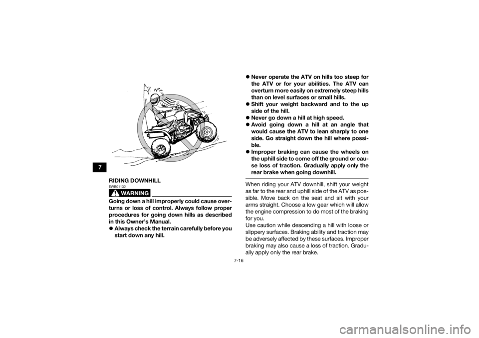
7RIDING DOWNHILL
WARNING
EWB01132Going down a hill improperly could cause over-
turns or loss of control. Always follow proper
procedures for going down hills as described
in this Owner’s Manual.
Always check the terrain carefully before you
start down any hill.
Never operate the ATV on hills too steep for
the ATV or for your abilities. The ATV can
overturn more easily on extremely steep hills
than on level surfaces or small hills.
Shift your weight backward and to the up
side of the hill.
Never go down a hill at high speed.
Avoid going down a hill at an angle that
would cause the ATV to lean sharply to one
side. Go straight down the hill where possi-
ble.
Improper braking can cause the wheels on
the uphill side to come off the ground or cau-
se loss of traction. Gradually apply only the
rear brake when going downhill.
When riding your ATV downhill, shift your weight
as far to the rear and uphill side of the ATV as pos-
sible. Move back on the seat and sit with your
arms straight. Choose a low gear which will allow
the engine compression to do most of the braking
for you.
Use caution while descending a hill with loose or
slippery surfaces. Braking ability and traction may
be adversely affected by these surfaces. Improper
braking may also cause a loss of traction. Gradu-
ally apply only the rear brake.
U2LS62E0.book Page 16 Thursday, February 25, 2016 8:44 AM
Page 93 of 160
8-1
8
EBU28787
PERIODIC MAINTENANCE AND ADJUSTMENT
EBU21675Periodic inspection, adjustment, and lubrication
will keep your vehicle in the safest and most effi-
cient condition possible. Safety is an obligation of
the vehicle owner/operator. The most important
points of vehicle inspection, adjustment, and lu-
brication are explained on the following pages.
WARNING
EWB01842Failure to properly maintain the vehicle or per-
forming maintenance activities incorrectly may
increase your risk of injury or death during ser-
vice or while using the vehicle. If you are not fa-
miliar with vehicle service, have a Yamaha
dealer perform the service.
WARNING
EWB02563Turn off the engine when performing mainte-
nance unless otherwise specified.
A running engine has moving parts that can
catch on body parts or clothing and electri-
cal parts that can cause shocks or fires.
Running the engine while servicing can lead
to eye injury, burns, fire, or carbon monoxide
poisoning - possibly leading to death. See
page 2-6 for more information about carbon
monoxide.
WARNING
EWB02691Brake discs, calipers, drums, and linings can
become very hot during use. To avoid possible
burns, let brake components cool before
touching them. The intervals given in the periodic maintenance
charts should be considered as a general guide
under normal riding conditions. However, DE-
PENDING ON THE WEATHER, TERRAIN, GEO-
GRAPHICAL LOCATION, AND INDIVIDUAL USE,
THE MAINTENANCE INTERVALS MAY NEED TO
BE SHORTENED.
U2LS62E0.book Page 1 Thursday, February 25, 2016 8:44 AM
Page 95 of 160
8-3
8
EBU21745Periodic maintenance chart for the emission control systemTIPFor ATVs not equipped with an odometer or an hour meter, follow the month maintenance intervals.
For ATVs equipped with an odometer or an hour meter, follow the km (mi) or hours maintenance inter-
vals. However, keep in mind that if the ATV isn’t used for a long period of time, the month maintenance
intervals should still be followed.
Items marked with an asterisk should be performed by a Yamaha dealer as they require special tools,
data and technical skills. NO. ITEM CHECK OR MAINTENANCE
JOB INITIAL
EVERY
Whichev- er comes first month136612
km (mi) 320
(200) 1300
(800) 2500
(1600) 2500
(1600) 5000
(3200)
hours 20 80 160 160 320
1 *Fuel line • Check fuel hoses for cracks or other damage, and
replace if necessary. √√√
2Spark plug • Check condition and clean, regap, or replace if
necessary. √√√√√
3 *Va l v e s • Check valve clearance and adjust if necessary. √ √√√
4 *Fuel injection • Check and adjust engine idle speed. √√√√√
5 *Crankcase breath-
er system • Check breather hose for cracks or other damage,
and replace if necessary. √√√
U2LS62E0.book Page 3 Thursday, February 25, 2016 8:44 AM
Page 99 of 160

8-7
8
14*Drive chain roller • Check for wear and replace if necessary. √√√
15 *Chassis fasteners • Make sure that all nuts, bolts, and screws are
properly tightened. √√√√√
16 *Shock absorber as-
semblies • Check operation and correct if necessary.
• Check for oil leakage and replace if necessary.
√√√
17 *Rear suspension re-
lay arm and con-
necting arm
pivoting points • Check operation and correct if necessary.
• Lubricate with lithium-soap-based grease.
√√√√
18 *Steering shaft • Lubricate with lithium-soap-based grease. √√√
19 *Steering system • Check operation and repair or replace if dam-
aged.
• Check toe-in and adjust if necessary. √√√√√
20 *Engine mount • Check for cracks or other damage, and replace if
necessary. √√√
21 Engine oil • Change.
• Check ATV for oil leakage, and correct if neces-
sary. √ √√√
22 Engine oil filter ele-
ment • Replace.
√√√
NO. ITEM
CHECK OR MAINTENANCE
JOB INITIAL EVERY
Whichev- er comes first month136612
km (mi) 320
(200) 1300
(800) 2500
(1600) 2500
(1600) 5000
(3200)
hours 20 80 160 160 320U2LS62E0.book Page 7 Thursday, February 25, 2016 8:44 AM
Page 102 of 160
8-10
8
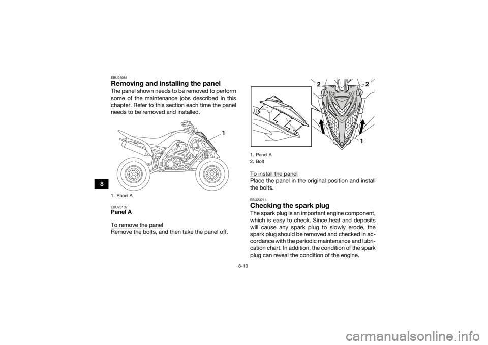
EBU23081Removing and installing the panelThe panel shown needs to be removed to perform
some of the maintenance jobs described in this
chapter. Refer to this section each time the panel
needs to be removed and installed.EBU23102Panel A
To remove the panelRemove the bolts, and then take the panel off.To install the panel
Place the panel in the original position and install
the bolts.EBU23214Checking the spark plugThe spark plug is an important engine component,
which is easy to check. Since heat and deposits
will cause any spark plug to slowly erode, the
spark plug should be removed and checked in ac-
cordance with the periodic maintenance and lubri-
cation chart. In addition, the condition of the spark
plug can reveal the condition of the engine.
1. Panel A
1
1. Panel A
2. Bolt
2
2
1
U2LS62E0.book Page 10 Thursday, February 25, 2016 8:44 AM
Page 103 of 160
8-11
8
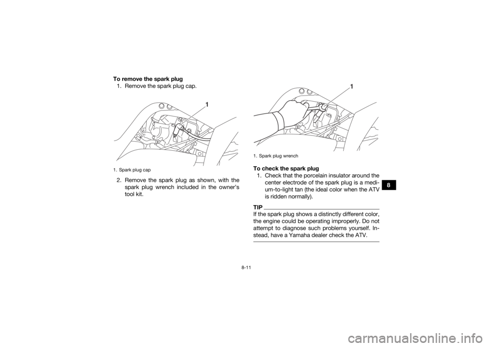
To remove the spark plug
1. Remove the spark plug cap.
2. Remove the spark plug as shown, with the spark plug wrench included in the owner’s
tool kit. To check the spark plug
1. Check that the porcelain insulator around the center electrode of the spark plug is a medi-
um-to-light tan (the ideal color when the ATV
is ridden normally).
TIPIf the spark plug shows a distinctly different color,
the engine could be operating improperly. Do not
attempt to diagnose such problems yourself. In-
stead, have a Yamaha dealer check the ATV.
1. Spark plug cap
1
1. Spark plug wrench
1
U2LS62E0.book Page 11 Thursday, February 25, 2016 8:44 AM
Page 105 of 160
8-13
8
EBU26788Engine oil and oil filter elementThe engine oil level should be checked before
each ride. In addition, the oil must be changed and
the oil filter element replaced at the intervals spec-
ified in the periodic maintenance and lubrication
chart.
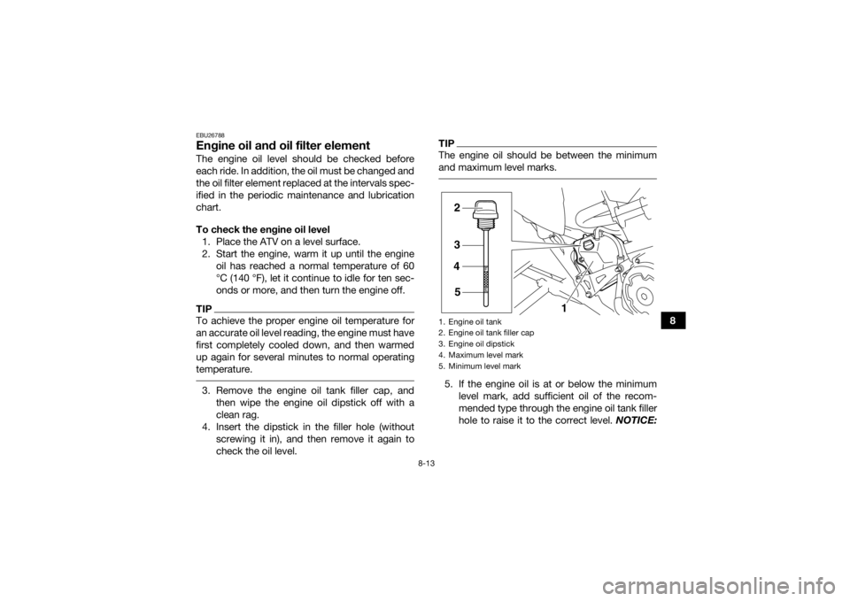
To check the engine oil level1. Place the ATV on a level surface.
2. Start the engine, warm it up until the engine oil has reached a normal temperature of 60
°C (140 °F), let it continue to idle for ten sec-
onds or more, and then turn the engine off.TIPTo achieve the proper engine oil temperature for
an accurate oil level reading, the engine must have
first completely cooled down, and then warmed
up again for several minutes to normal operating
temperature. 3. Remove the engine oil tank filler cap, andthen wipe the engine oil dipstick off with a
clean rag.
4. Insert the dipstick in the filler hole (without screwing it in), and then remove it again to
check the oil level.
TIPThe engine oil should be between the minimum
and maximum level marks. 5. If the engine oil is at or below the minimumlevel mark, add sufficient oil of the recom-
mended type through the engine oil tank filler
hole to raise it to the correct level. NOTICE:1. Engine oil tank
2. Engine oil tank filler cap
3. Engine oil dipstick
4. Maximum level mark
5. Minimum level mark
2
3
4
5 1
U2LS62E0.book Page 13 Thursday, February 25, 2016 8:44 AM
Page 106 of 160
![YAMAHA YFM700R 2017 Owners Guide 8-14
8Be sure the engine oil is at the correct lev-
el, otherwise engine damage may result.
[ECB00852]
TIPWhen adding oil, be careful not to overfill the en-
gine oil tank; the oil level rises faster YAMAHA YFM700R 2017 Owners Guide 8-14
8Be sure the engine oil is at the correct lev-
el, otherwise engine damage may result.
[ECB00852]
TIPWhen adding oil, be careful not to overfill the en-
gine oil tank; the oil level rises faster](/img/51/53753/w960_53753-105.png)
8-14
8Be sure the engine oil is at the correct lev-
el, otherwise engine damage may result.
[ECB00852]
TIPWhen adding oil, be careful not to overfill the en-
gine oil tank; the oil level rises faster starting from
the half-level-portion on the dipstick. 6. Insert the dipstick into the engine oil tank filler
hole, and then tighten the engine oil tank filler
cap. NOTICE: Make sure that the engine oil
tank filler cap is securely tightened; other-
wise, oil may seep out when the engine is
running.
[ECB00363]
To change the engine oil (with or without oil fil-
ter element replacement) 1. Place the ATV on a level surface.
2. Start the engine, warm it up for several minu- tes, and then turn it off.
3. Place an oil pan under the engine to collect the used oil.
4. Remove the crankcase engine oil filler bolt and its O-ring, and then remove the crank-
case engine oil drain bolt and its gasket.
1. Crankcase engine oil filler bolt
2. O-ring
1. Crankcase engine oil drain bolt
2. Gasket
2112
U2LS62E0.book Page 14 Thursday, February 25, 2016 8:44 AM
Page 107 of 160
8-15
8
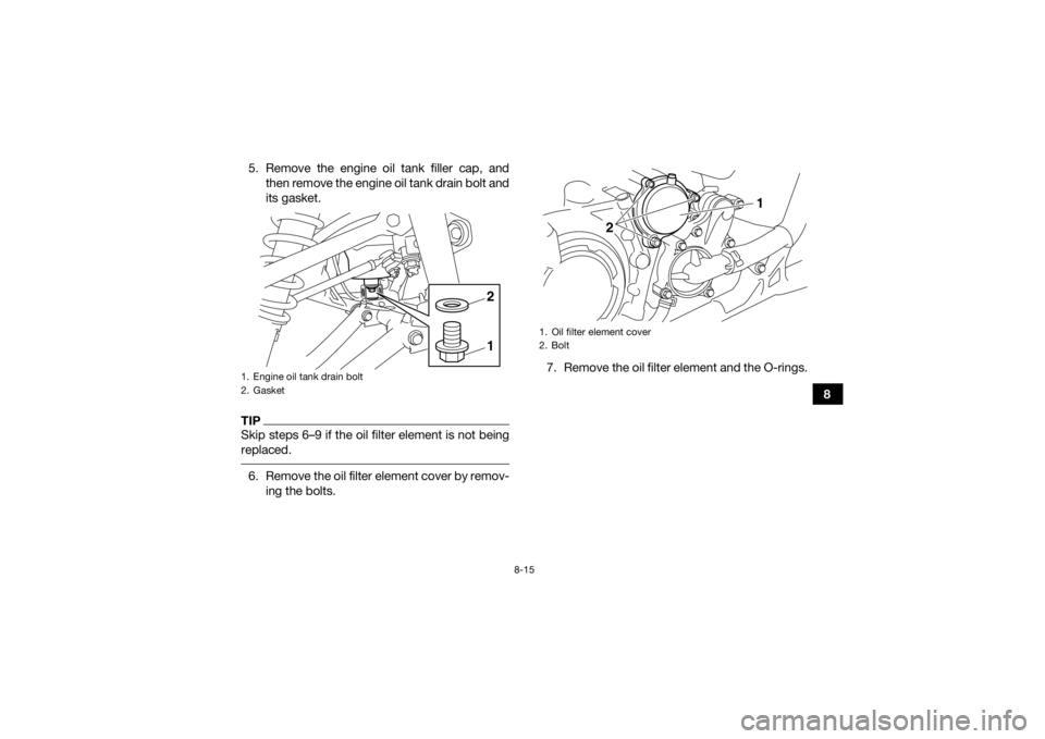
5. Remove the engine oil tank filler cap, and
then remove the engine oil tank drain bolt and
its gasket.
TIPSkip steps 6–9 if the oil filter element is not being
replaced. 6. Remove the oil filter element cover by remov-ing the bolts. 7. Remove the oil filter element and the O-rings.1. Engine oil tank drain bolt
2. Gasket
12
1. Oil filter element cover
2. Bolt
2
1
U2LS62E0.book Page 15 Thursday, February 25, 2016 8:44 AM