lock YAMAHA YFM700R 2020 User Guide
[x] Cancel search | Manufacturer: YAMAHA, Model Year: 2020, Model line: YFM700R, Model: YAMAHA YFM700R 2020Pages: 156, PDF Size: 4.19 MB
Page 45 of 156
5-20
5
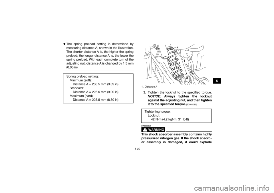
The spring preload setting is determined by
measuring distance A, shown in the illustration.
The shorter distance A is, the higher the spring
preload; the longer distance A is, the lower the
spring preload. With each complete turn of the
adjusting nut, distance A is changed by 1.5 mm
(0.06 in).
3. Tighten the locknut to the specified torque.
NOTICE: Always tighten the locknut
against the adjusting nut, and then tighten
it to the specified torque.
[ECB00082]
WARNING
EWB00451This shock absorber assembly contains highly
pressurized nitrogen gas. If the shock absorb-
er assembly is damaged, it could explode
Spring preload setting:
Minimum (soft):Distance A = 238.5 mm (9.39 in)
Standard: Distance A = 228.5 mm (9.00 in)
Maximum (hard): Distance A = 223.5 mm (8.80 in)1. Distance ATightening torque: Locknut:42 N·m (4.2 kgf·m, 31 lb·ft)
1
UBCX60E0.book Page 20 Friday, April 19, 2019 9:09 AM
Page 46 of 156

5-21
5causing injury or property damage. Shock ab-
sorber cylinder damage could also result in
poor handling which could cause an accident.
Do not tamper with or attempt to open the
cylinder assembly.
Do not subject the shock absorber assembly
to an open flame or other high heat.
Do not deform or damage the cylinder in any
way.
Do not dispose of a damaged or worn out
shock absorber assembly yourself. Take the
shock absorber assembly to a Yamaha deal-
er for any service.
EBU30996Rear shock absorber (For models
equipped with adjustable spring pre-
load and damping force)The shock absorber spring preload, rebound
damping force, and compression damping force
(fast and slow compression damping) can be ad-
justed.
WARNING
EWB02681Suspension components become hot during
operation. Never touch the compression
damping force adjusting bolt and screw, the
rebound damping force adjusting screw or the
oil reservoir with your bare hand or skin until
the suspension components have cooled. Notes on adjusting the suspension
A special wrench can be obtained at a Yamaha
dealer to make the spring preload adjustment.
When adjusting the damping force settings, turn
the adjuster in direction (a) until it stops, and
then count the turns or clicks in direction (b).
Although a damping force adjuster may turn or
click beyond the stated minimum settings, such
adjustments are ineffective and may damage
the suspension.NOTICEECB00091Never turn an adjusting mechanism beyond
the minimum and maximum settings. Spring preload
1. Loosen the locknut.
UBCX60E0.book Page 21 Friday, April 19, 2019 9:09 AM
Page 47 of 156
5-22
5
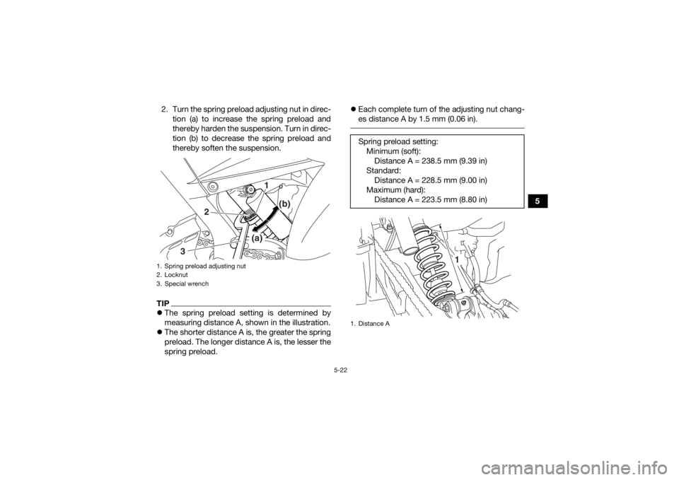
2. Turn the spring preload adjusting nut in direc-
tion (a) to increase the spring preload and
thereby harden the suspension. Turn in direc-
tion (b) to decrease the spring preload and
thereby soften the suspension.
TIPThe spring preload setting is determined by
measuring distance A, shown in the illustration.
The shorter distance A is, the greater the spring
preload. The longer distance A is, the lesser the
spring preload.
Each complete turn of the adjusting nut chang-
es distance A by 1.5 mm (0.06 in).
1. Spring preload adjusting nut
2. Locknut
3. Special wrench
1
(b)
(a)
2
3
Spring preload setting: Minimum (soft):Distance A = 238.5 mm (9.39 in)
Standard: Distance A = 228.5 mm (9.00 in)
Maximum (hard): Distance A = 223.5 mm (8.80 in)1. Distance A
1
UBCX60E0.book Page 22 Friday, April 19, 2019 9:09 AM
Page 48 of 156
![YAMAHA YFM700R 2020 User Guide 5-23
53. Tighten the locknut to the specified torque.
NOTICE: Always tighten the locknut
against the adjusting nut, and then tighten
it to the specified torque.
[ECB00082]
Rebound damping force
Turn YAMAHA YFM700R 2020 User Guide 5-23
53. Tighten the locknut to the specified torque.
NOTICE: Always tighten the locknut
against the adjusting nut, and then tighten
it to the specified torque.
[ECB00082]
Rebound damping force
Turn](/img/51/53744/w960_53744-47.png)
5-23
53. Tighten the locknut to the specified torque.
NOTICE: Always tighten the locknut
against the adjusting nut, and then tighten
it to the specified torque.
[ECB00082]
Rebound damping force
Turn the rebound damping force adjusting screw
in direction (a) to increase the rebound damping
force. Turn in direction (b) to decrease the re-
bound damping force. Compression damping force
Fast compression damping force
Turn the fast compression damping force adjust-
ing bolt in direction (a) to increase the fast com-
pression damping force. Turn in direction (b) to
decrease the fast compression damping force.
Tightening torque:
Locknut:42 N·m (4.2 kgf·m, 31 lb·ft)
1. Rebound damping force adjusting screw
1
(b) (a)
Rebound damping force settings:
Minimum (soft):30 click(s) in direction (b)
Standard: 18 click(s) in direction (b)
Maximum (hard): 1 click(s) in direction (b)1. Fast compression damping force adjusting bolt
1
(b)
(a)
1
UBCX60E0.book Page 23 Friday, April 19, 2019 9:09 AM
Page 61 of 156
7-4
7
Always use the clutch when changing gears.
The engine, transmission and drive train are
not designed to withstand the shock of
forced shifting and can be damaged by shift-
ing without using the clutch.
EBU20503Operating the reverse knob and driving
in reverse
WARNING
EWB00721Improper operation in reverse could make you
hit an obstacle or even a person behind you,
resulting in serious injury. When you shift into
reverse, make sure there are no people or ob-
stacles behind you. When it is safe to proceed,
go slowly. NOTICEECB00171Before shifting, stop the ATV, otherwise the
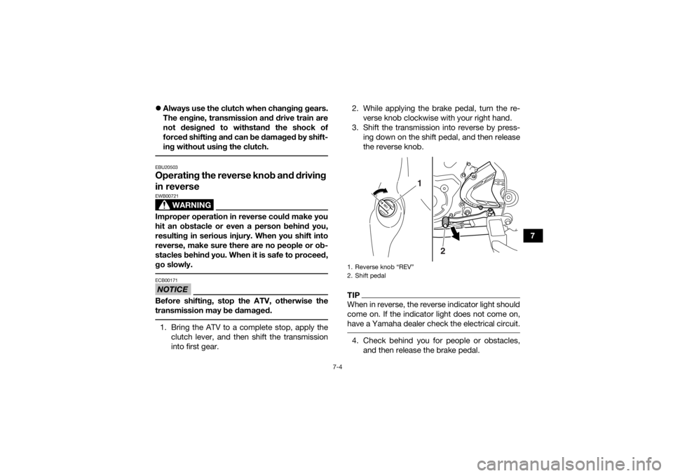
transmission may be damaged. 1. Bring the ATV to a complete stop, apply the
clutch lever, and then shift the transmission
into first gear. 2. While applying the brake pedal, turn the re-
verse knob clockwise with your right hand.
3. Shift the transmission into reverse by press- ing down on the shift pedal, and then release
the reverse knob.
TIPWhen in reverse, the reverse indicator light should
come on. If the indicator light does not come on,
have a Yamaha dealer check the electrical circuit. 4. Check behind you for people or obstacles,and then release the brake pedal.1. Reverse knob “REV”
2. Shift pedal
2
1
UBCX60E0.book Page 4 Friday, April 19, 2019 9:09 AM
Page 62 of 156
7-5
75. Open the throttle lever gradually and release
the clutch lever slowly. Continue to watch to
the rear while backing.
EBU20674Engine break-inThere is never a more important period in the life
of your engine than the first 320 km (200 mi) or 20
hours of operation. For this reason, you should fol-
low the engine break-in instructions carefully.
Since the engine is brand new, do not put an ex-
cessive load on it for the first 320 km (200 mi) or
20 hours. During this period the various parts in
the engine wear and polish themselves to the cor-
rect operating clearances. Avoid prolonged full-
throttle operation or any condition that might re-
sult in engine overheating.
0–160 km (0–100 mi) or 0–10 hours
Avoid prolonged operation above 1/2 throttle.
Vary the speed of the ATV regularly. Do not oper-
ate it at one set throttle position.
160–320 km (100–200 mi) or 10–20 hours
Avoid prolonged operation above 3/4 throttle. Rev
the engine through the gears freely, but do not use
full throttle at any time. 320 km (200 mi) or 20 hours and beyond
The ATV can now be operated normally.
NOTICEECB00221If any engine trouble should occur during the
engine break-in period, immediately have a
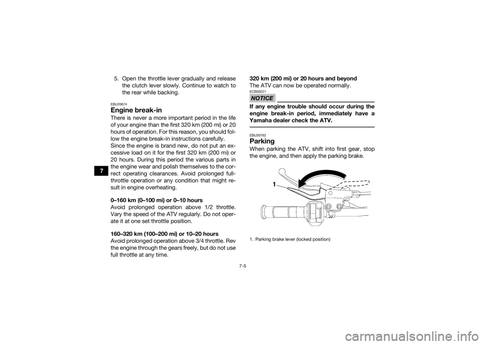
Yamaha dealer check the ATV. EBU26762ParkingWhen parking the ATV, shift into first gear, stop
the engine, and then apply the parking brake.1. Parking brake lever (locked position)
UBCX60E0.book Page 5 Friday, April 19, 2019 9:09 AM
Page 63 of 156
7-6
7
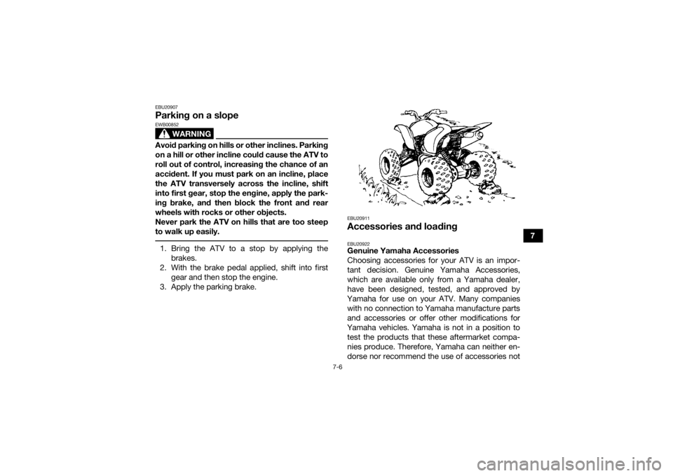
EBU20907Parking on a slope
WARNING
EWB00852Avoid parking on hills or other inclines. Parking
on a hill or other incline could cause the ATV to
roll out of control, increasing the chance of an
accident. If you must park on an incline, place
the ATV transversely across the incline, shift
into first gear, stop the engine, apply the park-
ing brake, and then block the front and rear
wheels with rocks or other objects.
Never park the ATV on hills that are too steep
to walk up easily. 1. Bring the ATV to a stop by applying thebrakes.
2. With the brake pedal applied, shift into first gear and then stop the engine.
3. Apply the parking brake.
EBU20911Accessories and loadingEBU20922Genuine Yamaha Accessories
Choosing accessories for your ATV is an impor-
tant decision. Genuine Yamaha Accessories,
which are available only from a Yamaha dealer,
have been designed, tested, and approved by
Yamaha for use on your ATV. Many companies with no connection to Yamaha manufacture parts
and accessories or offer other modifications for
Yamaha vehicles. Yamaha is not in a position to test the products that these aftermarket compa-
nies produce. Therefore, Yamaha can neither en-
dorse nor recommend the use of accessories not
UBCX60E0.book Page 6 Friday, April 19, 2019 9:09 AM
Page 70 of 156
8-5
8Pre-operation checks
Always inspect your ATV each time you use it to
make sure the ATV is in safe operating condition.
Perform the pre-operation checks listed on page
6-1. Always follow the inspection and mainte-
nance procedures and schedules described in the
Owner’s Manual.
WARNING! Failure to inspect
the ATV before riding it or failure to maintain it
properly increases the possibility of an acci-
dent and equipment damage.
[EWB01433]
Speed limiter
For riders less experienced with this model, the
throttle lever housing is equipped with a speed
limiter. The speed limiter keeps the throttle from fully opening, even when the throttle lever is
pushed to the maximum. Turning in the adjusting
screw limits the maximum engine power available
and decreases the maximum speed of the ATV.
Turning in the adjusting screw decreases top
speed, and turning it out increases top speed.
(See page 5-5.)
Loading and accessories
WARNING
EWB00973Improper loading or towing can increase the
risk of loss of control, an overturn, or other ac-
cident. To reduce the risk of an accident:1. Locknut
2. Adjusting screw
12
UBCX60E0.book Page 5 Friday, April 19, 2019 9:09 AM
Page 80 of 156

8-15
8It is important when climbing a hill to make sure
that your weight is transferred forward on the ATV.
This can be accomplished by leaning forward and,
on steeper inclines, standing on the footrests and
leaning forward over the handlebars. Whenever
possible, ride straight up hills.
Slow down when you reach the crest of the hill if
you cannot see clearly what is on the other side –
there could be another person, an obstacle, or a
sharp drop-off. Use common sense and remem-
ber that some hills are too steep for you to climb
or descend.
If you are climbing a hill and you find that you have
not properly judged your ability to make it to the
top, you should turn the ATV around while you still
have forward motion (provided you have the room
to do so) and go down the hill.
If your ATV has stalled or stopped and you believe
you can continue up the hill, restart carefully to
make sure you do not lift the front wheels which
could cause you to lose control. If you are unable
to continue up the hill, dismount the ATV on the
uphill side. Physically turn the ATV around and
then descend the hill. If you start to roll backwards, DO NOT apply the
rear brake, and apply the front brake gradually.
The ATV could easily tip over backwards. When
fully stopped, apply the rear brake as well, and
then lock the parking brake. Dismount the ATV im-
mediately on the uphill side or to a side if pointed
straight uphill. Turn the ATV around and remount,
following the procedure described in the Owner’s
Manual.
WARNING! Stalling, rolling backwards
or improperly dismounting while climbing a hill
could result in ATV overturning. If you cannot
control the ATV, dismount immediately on the
uphill side.
[EWB01803]
UBCX60E0.book Page 15 Friday, April 19, 2019 9:09 AM
Page 95 of 156

9-8
9
EBU23072TIPSome maintenance items need more frequent service if you are riding in unusually wet, dusty, sandy or
muddy areas, or at full-throttle.23 Cooling system • Check coolant level and ATV for coolant leakage,
and correct if necessary. √√√√√
• Replace coolant. Every 2 years
24 *Moving parts and
cables •Lubricate.
√√√√
25 *Reverse lock re-
lease cable • Check operation and adjust or replace if neces-
sary. √√√
26 *Throttle lever • Check operation.
• Check throttle lever free play, and adjust if neces-
sary.
• Lubricate cable and lever housing. √√√√√
27 *Front and rear
brake switches • Check operation and correct if necessary.
√√√√√
28 *Lights and switches • Check operation and correct if necessary.
• Adjust headlight beams. √√√√√
NO. ITEM
CHECK OR MAINTENANCE
JOB INITIAL EVERY
Whichev- er comes first month136612
km (mi) 320
(200) 1300
(800) 2500
(1600) 2500
(1600) 5000
(3200)
hours 20 80 160 160 320UBCX60E0.book Page 8 Friday, April 19, 2019 9:09 AM