clutch YAMAHA YFM700R 2021 Owners Manual
[x] Cancel search | Manufacturer: YAMAHA, Model Year: 2021, Model line: YFM700R, Model: YAMAHA YFM700R 2021Pages: 150, PDF Size: 3.63 MB
Page 8 of 150

EBU17421
TABLE OF CONTENTS
VEHICLE IDENTIFICATION ............................ 1-1Identification numbers ................................ 1-1
LOCATION OF THE WARNING AND
SPECIFICATION LABELS .............................. 2-1
SAFETY INFORMATION ................................ 3-1
DESCRIPTION................................................ 4-1 Left view ...................................................... 4-1
Right view.................................................... 4-1
Controls and instruments............................ 4-2
INSTRUMENT AND CONTROL
FUNCTIONS ................................................... 5-1 Main switch ................................................. 5-1
Indicator lights and warning lights .............. 5-1
Self-diagnostic device................................. 5-3
Handlebar switches .................................... 5-3
Throttle lever ............................................... 5-4
Speed limiter ............................................... 5-5
Clutch lever ................................................. 5-5
Brake lever .................................................. 5-6
Brake pedal ................................................. 5-6 Parking brake lever ..................................... 5-7
Shift pedal................................................... 5-8
Reverse knob “REV” ................................... 5-8
Fuel tank cap .............................................. 5-9
Fuel ........................................................... 5-10
Seat .......................................................... 5-11
Front shock absorbers ............................ 5-12
Rear shock absorber assembly ................ 5-16
PRE-OPERATION CHECKS .......................... 6-1 Fuel ............................................................. 6-4
Engine oil .................................................... 6-4
Coolant ....................................................... 6-4
Front and rear brakes ................................. 6-4
Throttle lever ............................................... 6-5
Drive chain .................................................. 6-5
Tires ............................................................ 6-5
Chassis fasteners ....................................... 6-7
Instruments, lights and switches ................ 6-7
OPERATION .................................................. 7-1 Starting the engine ..................................... 7-1
Shifting........................................................ 7-2UBCX61E0.book Page 1 Friday, January 22, 2021 1:54 PM
Page 9 of 150

Operating the reverse knob and driving in reverse ...................................................... 7-4
Engine break-in ........................................... 7-5
Parking ........................................................ 7-5
Parking on a slope ...................................... 7-6
Accessories and loading ............................. 7-6
RIDING YOUR ATV ........................................ 8-1 GETTING TO KNOW YOUR ATV ................ 8-2
RIDE WITH CARE AND GOOD JUDGMENT .............................................. 8-2
BE CAREFUL WHERE YOU RIDE ............... 8-8
TURNING YOUR ATV................................ 8-11
CLIMBING UPHILL ................................... 8-13
RIDING DOWNHILL .................................. 8-16
CROSSING A SLOPE................................ 8-17
CROSSING THROUGH SHALLOW WATER .................................................... 8-18
RIDING OVER ROUGH TERRAIN ............. 8-20
SLIDING AND SKIDDING.......................... 8-20
WHAT TO DO IF... ..................................... 8-21
PERIODIC MAINTENANCE AND
ADJUSTMENT................................................ 9-1 Owner’s Manual and tool kit ....................... 9-2
Periodic maintenance chart: Emission control system .......................................... 9-3 Periodic maintenance chart: General
maintenance and lubrication .................... 9-5
Removing and installing the panel............ 9-10
Checking the spark plug........................... 9-10
Engine oil and oil filter element................. 9-12
Why Yamalube ......................................... 9-17
Coolant ..................................................... 9-18
Cleaning the air filter element ................... 9-21
Cleaning the spark arrester ...................... 9-25
Adjusting the engine idling speed ............ 9-27
Adjusting the throttle lever free play ......... 9-28
Valve clearance......................................... 9-29
Adjusting the reverse lock release cable ....................................................... 9-29
Brakes....................................................... 9-29
Checking the front and rear brake pads... 9-29
Checking the brake fluid level .................. 9-30
Changing the brake fluid .......................... 9-33
Checking the front brake lever free play... 9-33
Checking the brake pedal height.............. 9-34
Adjusting the parking brake free play ....... 9-34
Brake light switches ................................. 9-36
Adjusting the clutch lever free play .......... 9-36
Drive chain slack....................................... 9-38
Lubricating the drive chain ....................... 9-40
Checking and lubricating the cables ........ 9-40
UBCX61E0.book Page 2 Friday, January 22, 2021 1:54 PM
Page 10 of 150

Checking and lubricating the brake and clutch levers ............................................ 9-41
Checking the shift pedal ........................... 9-41
Checking and lubricating the brake pedal ....................................................... 9-41
Checking the wheel hub bearings............. 9-42
Lubricating the swingarm pivots ............... 9-42
Lubricating the rear suspension relay arm and connecting arm pivoting points ....... 9-43
Lubricating the upper and lower arm pivots ...................................................... 9-44
Lubricating the steering shaft ................... 9-45
Battery....................................................... 9-45
Replacing a fuse ....................................... 9-49
Replacing a headlight bulb ....................... 9-50
Adjusting a headlight beam ...................... 9-52
Brake/tail light ........................................... 9-52
Removing a wheel ..................................... 9-52
Installing a wheel....................................... 9-53
Troubleshooting ........................................ 9-54
Troubleshooting charts ............................. 9-55
CLEANING AND STORAGE ......................... 10-1 Cleaning .................................................... 10-1
Storage...................................................... 10-2 SPECIFICATIONS ........................................ 11-1
INDEX .......................................................... 12-1
UBCX61E0.book Page 3 Friday, January 22, 2021 1:54 PM
Page 25 of 150

4-2
4
EBU17715Controls and instruments1. Clutch lever
2. Parking brake lever
3. Main switch
4. Front brake fluid reservoir
5. Brake lever
6. Throttle lever
7. Reverse knob
8. Handlebar switches
12 3
4
5
67
8
UBCX61E0.book Page 2 Friday, January 22, 2021 1:54 PM
Page 30 of 150

5-5
5
EBU18325Speed limiterThe speed limiter keeps the throttle from fully
opening, even when the throttle lever is pushed to
the maximum.
Adjusting the speed limiter1. Loosen the locknut.
2. To increase the maximum engine poweravailable and the maximum speed of the ATV,
turn the adjusting screw in direction (a). To
decrease the maximum engine power avail-
able and the maximum speed of the ATV, turn the adjusting screw in direction (b). Do not
turn the adjusting screw out more than 12
mm (0.47 in) or the throttle cable could be
damaged. Always make sure the throttle lever
free play is adjusted to 2.0–4.0 mm (0.08–
0.16 in). (See page 9-28.) WARNING! Im-
proper adjustment of the speed limiter and
throttle could cause throttle cable damage
or improper throttle operation. You could
lose control, resulting in an accident.
[EWB00242]
3. Tighten the locknut.EBU18384Clutch lever
1. Locknut
2. Adjusting screw
3. No more than 12 mm (0.47 in)
3
12
(a)
(b)
1. Clutch lever
UBCX61E0.book Page 5 Friday, January 22, 2021 1:54 PM
Page 31 of 150

5-6
5
The clutch lever is located on the left side of the
handlebar. To disengage the clutch, pull the clutch
lever toward the handlebar grip. To engage the
clutch, release the lever. The lever should be
pulled rapidly and released slowly for smooth
clutch operation.
The clutch lever is equipped with a clutch switch,
which is part of the ignition circuit cut-off system.
(See page 7-1.)
EBU18426Brake lever
The brake lever is located on the right side of the
handlebar. To apply the front brake, pull the brake
lever toward the handlebar grip.
The brake lever is equipped with a position adjust-
ing bolt. To adjust the distance between the brake
lever and the handlebar grip, hold the brake lever
away from the handlebar so it does not contact
the adjusting bolt, loosen the locknut, turn the ad-
justing bolt, and then tighten the locknut.EBU18434Brake pedal
1. Brake lever
2. Locknut
3. Brake lever position adjusting bolt
4. Distance between brake lever and handlebar grip
1. Brake pedal
1
UBCX61E0.book Page 6 Friday, January 22, 2021 1:54 PM
Page 33 of 150

5-8
5
braking performance which could cause an
accident. You could also wear out the brakes
prematurely.
EBU18542Shift pedalThe shift pedal is located on the left side of the en-
gine and is used in combination with the clutch le-
ver when shifting. (See page 7-2.)
EBU18643Reverse knob “REV”The reverse knob is used when shifting into re-
verse. (See page 7-4.)
1. Shift pedal
1
1.
1
UBCX61E0.book Page 8 Friday, January 22, 2021 1:54 PM
Page 48 of 150
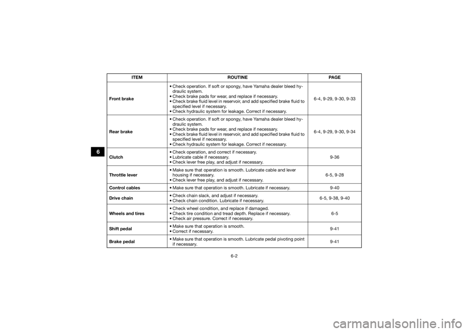
6-2
6
Front brake• Check operation. If soft or spongy, have Yamaha dealer bleed hy-
draulic system.
• Check brake pads for wear, and replace if necessary.
• Check brake fluid level in reservoir, and add specified brake fluid to specified level if necessary.
• Check hydraulic system for leakage. Correct if necessary. 6-4, 9-29, 9-30, 9-33
Rear brake • Check operation. If soft or spongy, have Yamaha dealer bleed hy-
draulic system.
• Check brake pads for wear, and replace if necessary.
• Check brake fluid level in reservoir, and add specified brake fluid to specified level if necessary.
• Check hydraulic system for leakage. Correct if necessary. 6-4, 9-29, 9-30, 9-34
Clutch • Check operation, and correct if necessary.
• Lubricate cable if necessary.
• Check lever free play, and adjust if necessary. 9-36
Throttle lever • Make sure that operation is smooth. Lubricate cable and lever
housing if necessary.
• Check lever free play, and adjust if necessary. 6-5, 9-28
Control cables • Make sure that operation is smooth. Lubricate if necessary. 9-40
Drive chain • Check chain slack, and adjust if necessary.
• Check chain condition. Lubricate if necessary. 6-5, 9-38, 9-40
Wheels and tires • Check wheel condition, and replace if damaged.
• Check tire condition and tread depth. Replace if necessary.
• Check air pressure. Correct if necessary. 6-5
Shift pedal • Make sure that operation is smooth.
• Correct if necessary.
9-41
Brake pedal • Make sure that operation is smooth. Lubricate pedal pivoting point
if necessary. 9-41
ITEM ROUTINE PAGEUBCX61E0.book Page 2 Friday, January 22, 2021 1:54 PM
Page 49 of 150

6-3
6
Brake and clutch levers• Make sure that operation is smooth. Lubricate lever pivoting points
if necessary. 9-41
Chassis fasteners • Make sure that all nuts, bolts and screws are properly tightened. 6-7
Instruments, lights and
switches • Check operation, and correct if necessary.
6-7
ITEM
ROUTINE PAGE
UBCX61E0.book Page 3 Friday, January 22, 2021 1:54 PM
Page 54 of 150
7-1
7
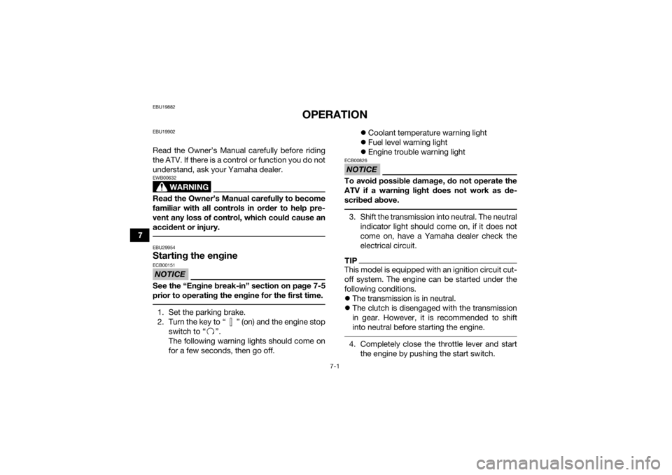
EBU19882
OPERATION
EBU19902Read the Owner’s Manual carefully before riding
the ATV. If there is a control or function you do not
understand, ask your Yamaha dealer.
WARNING
EWB00632Read the Owner’s Manual carefully to become
familiar with all controls in order to help pre-
vent any loss of control, which could cause an
accident or injury. EBU29954Starting the engineNOTICEECB00151See the “Engine break-in” section on page 7-5
prior to operating the engine for the first time. 1. Set the parking brake.
2. Turn the key to “ ” (on) and the engine stopswitch to “ ”.
The following warning lights should come on
for a few seconds, then go off.
Coolant temperature warning light
Fuel level warning light
Engine trouble warning light
NOTICEECB00826To avoid possible damage, do not operate the
ATV if a warning light does not work as de-
scribed above. 3. Shift the transmission into neutral. The neutral
indicator light should come on, if it does not
come on, have a Yamaha dealer check the
electrical circuit.TIPThis model is equipped with an ignition circuit cut-
off system. The engine can be started under the
following conditions.
The transmission is in neutral.
The clutch is disengaged with the transmission
in gear. However, it is recommended to shift
into neutral before starting the engine. 4. Completely close the throttle lever and start
the engine by pushing the start switch.
UBCX61E0.book Page 1 Friday, January 22, 2021 1:54 PM