torque YAMAHA YFM700R 2021 Owners Manual
[x] Cancel search | Manufacturer: YAMAHA, Model Year: 2021, Model line: YFM700R, Model: YAMAHA YFM700R 2021Pages: 150, PDF Size: 3.63 MB
Page 39 of 150
![YAMAHA YFM700R 2021 Owners Manual 5-14
5
4. Tighten the locknut to the specified torque. NOTICE: Always tighten the locknut
against the adjusting nut, and then tighten
it to the specified torque.
[ECB00082]
Rebound damping force
Tur YAMAHA YFM700R 2021 Owners Manual 5-14
5
4. Tighten the locknut to the specified torque. NOTICE: Always tighten the locknut
against the adjusting nut, and then tighten
it to the specified torque.
[ECB00082]
Rebound damping force
Tur](/img/51/53742/w960_53742-38.png)
5-14
5
4. Tighten the locknut to the specified torque. NOTICE: Always tighten the locknut
against the adjusting nut, and then tighten
it to the specified torque.
[ECB00082]
Rebound damping force
Turn the rebound damping force adjusting screw
in direction (a) to increase the rebound damping
force. Turn in direction (b) to decrease the re-
bound damping force.
Spring preload setting:
Minimum (soft):Distance A = 268.0 mm (10.55 in)
Standard: Distance A = 262.0 mm (10.31 in)
Maximum (hard): Distance A = 253.0 mm (9.96 in)
1. Distance A
1
Tightening torque: Locknut:42 N·m (4.2 kgf·m, 31 lb·ft)1. Rebound damping force adjusting screw
1(a)
(b)
UBCX61E0.book Page 14 Friday, January 22, 2021 1:54 PM
Page 43 of 150

5-18
5
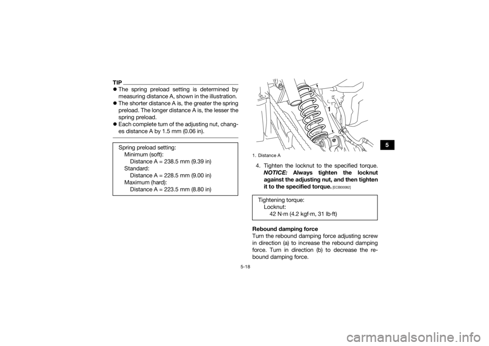
TIPThe spring preload setting is determined by
measuring distance A, shown in the illustration.
The shorter distance A is, the greater the spring
preload. The longer distance A is, the lesser the
spring preload.
Each complete turn of the adjusting nut, chang-
es distance A by 1.5 mm (0.06 in).
4. Tighten the locknut to the specified torque.
NOTICE: Always tighten the locknut
against the adjusting nut, and then tighten
it to the specified torque.
[ECB00082]
Rebound damping force
Turn the rebound damping force adjusting screw
in direction (a) to increase the rebound damping
force. Turn in direction (b) to decrease the re-
bound damping force.
Spring preload setting:
Minimum (soft):Distance A = 238.5 mm (9.39 in)
Standard: Distance A = 228.5 mm (9.00 in)
Maximum (hard): Distance A = 223.5 mm (8.80 in)1. Distance ATightening torque: Locknut:42 N·m (4.2 kgf·m, 31 lb·ft)
1
UBCX61E0.book Page 18 Friday, January 22, 2021 1:54 PM
Page 85 of 150

9-2
9
EBU27113Owner’s Manual and tool kitBe sure to put the Owner’s Manual in the plastic
bag and to always carry it as well as the tool kit
and the low-pressure tire gauge in their respective
compartments under the seat.
The information included in this manual and the
tools provided in the tool kit are intended to assist
you in the performance of preventive maintenance
and minor repairs. However, additional tools such
as a torque wrench are necessary to perform cer-
tain maintenance work correctly.
TIPIf you do not have the tools or experience required
for a particular job, have a Yamaha dealer perform
it for you.
1. Owner’s Manual
2. Tool kit
3. Low-pressure tire gauge
1
2 1
23
UBCX61E0.book Page 2 Friday, January 22, 2021 1:54 PM
Page 95 of 150

9-12
9
2. Check the spark plug for electrode erosion
and excessive carbon or other deposits, and
replace it if necessary.
3. Measure the spark plug gap with a wire thick- ness gauge and, if necessary, adjust the gap
to specification. To install the spark plug
1. Clean the surface of the spark plug gasket and its mating surface, and then wipe off any
grime from the spark plug threads.
2. Install the spark plug with the spark plug wrench, and then tighten it to the specified
torque.
TIPIf a torque wrench is not available when installing
the spark plug, a good estimate of the correct
torque is 1/4–1/2 turn past finger tight. However,
the spark plug should be tightened to the speci-
fied torque as soon as possible. 3. Install the spark plug cap.EBU2678DEngine oil and oil filter elementThe engine oil level should be checked before
each ride. In addition, the oil must be changed and
the oil filter element replaced at the intervals spec-
ified in the periodic maintenance chart.
Specified spark plug:
NGK/CR8E
1. Spark plug gapSpark plug gap:0.7–0.8 mm (0.028–0.031 in)
Tightening torque:Spark plug:13 N·m (1.3 kgf·m, 9.6 lb·ft)
UBCX61E0.book Page 12 Friday, January 22, 2021 1:54 PM
Page 99 of 150

9-16
9
8. Install a new oil filter element and new O-
rings.
TIPMake sure that the O-rings are properly seated. 9. Install the oil filter element cover by installingthe bolts, and then tighten them to the speci-
fied torque. 10. Install the crankcase engine oil drain bolt, the
engine oil tank drain bolt and their new gas-
ket, and then tighten the bolts to the specified
torques.
11. Install the crankcase engine oil filler bolt and its new O-ring, and then tighten the oil filler
bolt to the specified torque.
12. Pour only 1.3 L (1.37 US qt, 1.14 Imp.qt) of the specified amount of the recommended
engine oil through the engine oil tank filler
hole, and then install and tighten the oil tank
filler cap.
13. Start the engine, rev it several times, and then turn it off.1. Oil filter element
2. O-ringTightening torque:Oil filter element cover bolt:10 N
Page 104 of 150

9-21
95. Remove the coolant reservoir cap.
6. Disconnect the coolant reservoir hose on the
coolant reservoir side, and then drain the
coolant from the coolant reservoir.
7. After draining the coolant, thoroughly flush the cooling system with clean tap water.
8. Install the coolant drain bolt and its new gas- ket, and then tighten the bolt to the specified
torque. 9. Connect the coolant reservoir hose.
10. Pour the recommended coolant into the res- ervoir to the maximum level mark, and then
install the reservoir cap.
11. Pour the recommended coolant into the radi- ator until it is full, and then install the radiator
cap.
12. Start the engine, let it idle for several minutes, and then turn it off.
TIPWhile the engine is idling, check the cooling sys-
tem for leaks. 13. When the engine is cool, remove the radiatorcap to check the coolant level in the radiator.
If it is low, add sufficient coolant until it reach-
es the top of the radiator, and then install the
radiator cap.
14. Install the panel.EBU2680BCleaning the air filter elementThe air filter element should be cleaned at the in-
tervals specified in the periodic maintenance
chart. Clean or, if necessary, replace the air filter
element more frequently if you are riding in unusu-
ally wet or dusty areas.
1. Coolant reservoir cap
2. Coolant reservoir hoseTightening torque: Coolant drain bolt:11 N·m (1.1 kgf·m, 8.1 lb·ft)
1
2
UBCX61E0.book Page 21 Friday, January 22, 2021 1:54 PM
Page 110 of 150

9-27
94. Install the gasket, tailpipe, and retainer and
align the bolt holes.
5. Install the bolts and tighten them to the spec- ified torque.
6. Install the tailpipe cover and align the bolt holes.
7. Install the bolts and tighten them to the spec- ified torque.
EBU26813Adjusting the engine idling speedThe engine idling speed must be checked and, if
necessary, adjusted as follows at the intervals
specified in the periodic maintenance chart.TIPA diagnostic tachometer is needed to make this
adjustment. 1. Start the engine and warm it up.
2. Attach the tachometer to the spark plug lead.
3. Check the engine idling speed and, if neces-sary, adjust it to specification by turning the
idle adjusting screw. To increase the engine
idling speed, turn the idle adjusting screw in
direction (a), and to decrease it, turn the
screw in direction (b).
1. Tailpipe
2. Spark arresterTightening torque:Retainer bolt:10 N
Page 118 of 150

9-35
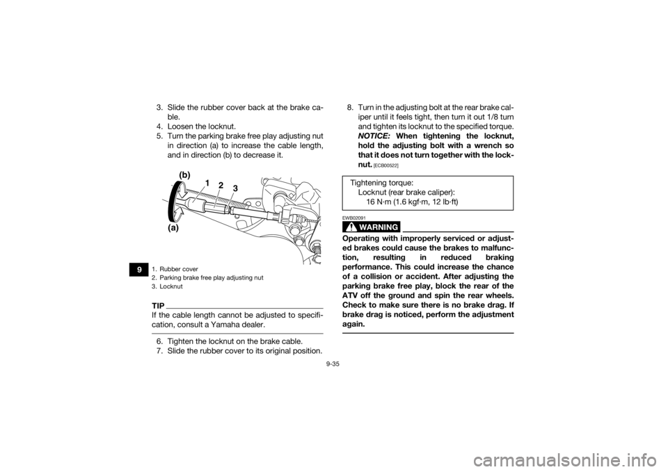
93. Slide the rubber cover back at the brake ca-
ble.
4. Loosen the locknut.
5. Turn the parking brake free play adjusting nut in direction (a) to increase the cable length,
and in direction (b) to decrease it.
TIPIf the cable length cannot be adjusted to specifi-
cation, consult a Yamaha dealer. 6. Tighten the locknut on the brake cable.
7. Slide the rubber cover to its original position. 8. Turn in the adjusting bolt at the rear brake cal-
iper until it feels tight, then turn it out 1/8 turn
and tighten its locknut to the specified torque.
NOTICE: When tightening the locknut,
hold the adjusting bolt with a wrench so
that it does not turn together with the lock-
nut.
[ECB00522]
WARNING
EWB02091Operating with improperly serviced or adjust-
ed brakes could cause the brakes to malfunc-
tion, resulting in reduced braking
performance. This could increase the chance
of a collision or accident. After adjusting the
parking brake free play, block the rear of the
ATV off the ground and spin the rear wheels.
Check to make sure there is no brake drag. If
brake drag is noticed, perform the adjustment
again.
1. Rubber cover
2. Parking brake free play adjusting nut
3. Locknut
1
(b)
(a) 2
3
Tightening torque:
Locknut (rear brake caliper):16 N·m (1.6 kgf·m, 12 lb·ft)
UBCX61E0.book Page 35 Friday, January 22, 2021 1:54 PM
Page 122 of 150

9-39
9
TIPA rod can be obtained at a Yamaha dealer to make
this adjustment. 4. Shift the transmission into neutral.
5. To tighten the drive chain, push the ATVbackward. To loosen the drive chain, push
the ATV forward. NOTICE: Improper drive
chain slack will overload the engine as well
as other vital parts of the ATV and can lead
to drive chain slippage or breakage. To prevent this from occurring, keep the drive
chain slack within the specified limits.
[ECB00543]
6. Pull the rod out, and then tighten the rear axle
pinch bolts to the specified torque in the or-
der shown.
1. Rear wheel axle pinch bolt
2. Rod
3. Drive chain tensioner
4. Hole
4
2
11
3
Tightening torque:
Rear axle pinch bolt:21 N·m (2.1 kgf·m, 15 lb·ft)
3 1 24
UBCX61E0.book Page 39 Friday, January 22, 2021 1:54 PM
Page 136 of 150

9-53
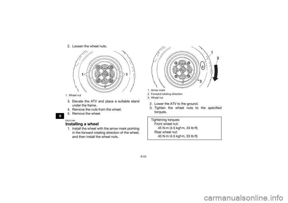
92. Loosen the wheel nuts.
3. Elevate the ATV and place a suitable stand
under the frame.
4. Remove the nuts from the wheel.
5. Remove the wheel.
EBU27484Installing a wheel1. Install the wheel with the arrow mark pointing in the forward rotating direction of the wheel,
and then install the wheel nuts. 2. Lower the ATV to the ground.
3. Tighten the wheel nuts to the specified
torques.1. Wheel nut
1. Arrow mark
2. Forward rotating direction
3. Wheel nutTightening torques:Front wheel nut:45 N·m (4.5 kgf·m, 33 lb·ft)
Rear wheel nut: 45 N·m (4.5 kgf·m, 33 lb·ft)
1
2
3
UBCX61E0.book Page 53 Friday, January 22, 2021 1:54 PM