torque YAMAHA YFM80R 2002 Owners Manual
[x] Cancel search | Manufacturer: YAMAHA, Model Year: 2002, Model line: YFM80R, Model: YAMAHA YFM80R 2002Pages: 342, PDF Size: 5.82 MB
Page 109 of 342

5-17
EBU00151Throttle lever
Check to see that the throttle lever operates cor-
rectly. It must open smoothly and spring back to
idle position when released. Repair as neces-
sary for proper operation.EBU00152Fittings and Fasteners
Always check the tightness of chassis fittings
and fasteners before a ride. Take the machine
to a Yamaha dealer or refer to the Service
Manual for correct tightening torque. EBU00154Switches
Check the operation of the start switch, engine
stop switch and any other switches. Repair as
necessary for proper operation.EBU00499Battery
Check fluid level and fill if necessary. Use only
distilled water if refilling is necessary. (See
pages 8-59 ~ 8-65.)
5TH-9-60 4~5 9/25/01 4:23 PM Page 42
Page 239 of 342

8-3
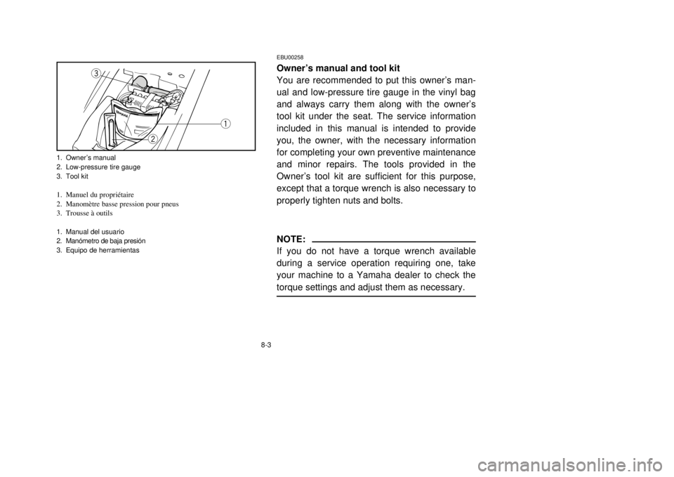
EBU00258Owner’s manual and tool kit
You are recommended to put this owner’s man-
ual and low-pressure tire gauge in the vinyl bag
and always carry them along with the owner’s
tool kit under the seat. The service information
included in this manual is intended to provide
you, the owner, with the necessary information
for completing your own preventive maintenance
and minor repairs. The tools provided in the
Owner’s tool kit are sufficient for this purpose,
except that a torque wrench is also necessary to
properly tighten nuts and bolts.NOTE:
If you do not have a torque wrench available
during a service operation requiring one, take
your machine to a Yamaha dealer to check the
torque settings and adjust them as necessary.
q
w
e
1. Owner’s manual
2. Low-pressure tire gauge
3. Tool kit1. Manuel du propriétaire
2. Manomètre basse pression pour pneus
3. Trousse à outils1. Manual del usuario
2. Manómetro de baja presión
3. Equipo de herramientas
5TH-9-60 8 9/25/01 5:50 PM Page 8-3
Page 251 of 342

8-15
Engine oil replacement
1. Place the ATV on a level place.
2. Warm up the engine for several minutes
and stop it.
3. Place a container under the engine.
4. Remove the dipstick and drain bolt to drain
the oil.
5. Inspect the O-ring and replace if damaged.
6. Install the drain bolt and tighten to specifi-
cation.
q
1. Drain bolt1. Bouchon de vidange1. Perno de drenaje
Tightening torque:
Drain bolt:
20 Nm (2.0 m0kgf)
5TH-9-60 8 9/25/01 5:50 PM Page 8-15
Page 257 of 342

8-21
2. Place a container under the final gear
case.
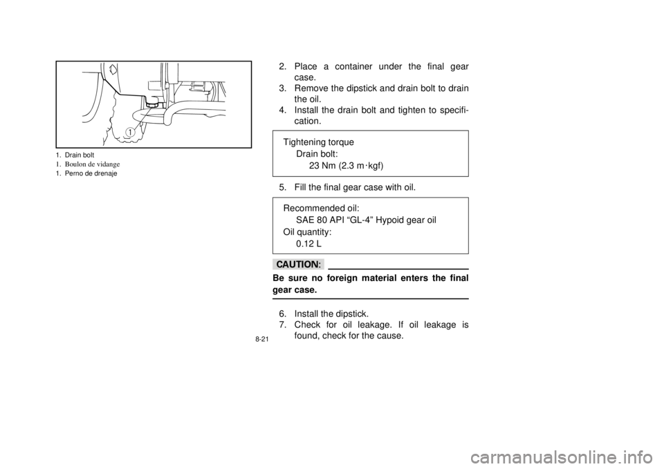
3. Remove the dipstick and drain bolt to drain
the oil.
4. Install the drain bolt and tighten to specifi-
cation.
5. Fill the final gear case with oil.cCBe sure no foreign material enters the final
gear case.6. Install the dipstick.
7. Check for oil leakage. If oil leakage is
found, check for the cause.
q
1. Drain bolt1. Boulon de vidange1. Perno de drenaje
Tightening torque
Drain bolt:
23 Nm (2.3 m0kgf)Recommended oil:
SAE 80 API “GL-4” Hypoid gear oil
Oil quantity:
0.12 L
5TH-9-60 8 9/25/01 5:50 PM Page 8-21
Page 261 of 342

8-25
Before installing the spark plug, measure the
electrode gap with a feeler gauge and adjust to
specification.
When installing the spark plug, always clean the
gasket surface and use a new gasket. Wipe off
any grime from the threads and tighten to the
specified torque.
a
a. Spark plug gapa. Écartement des électrodesa. Separación entre electrodos de la bujía
Spark plug gap:
0.6 ~ 0.7 mmTightening torque:
Spark plug:
12.5 Nm (1.25 m0kgf)Standard spark plug:
CR7HS (NGK)
5TH-9-60 8 9/25/01 5:50 PM Page 8-25
Page 287 of 342

8-51
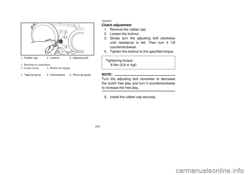
EBU00872Clutch adjustment
1. Remove the rubber cap.
2. Loosen the locknut.
3. Slowly turn the adjusting bolt clockwise
until resistance is felt. Then turn it 1/8
counterclockwise.
4. Tighten the locknut to the specified torque.NOTE:
Turn the adjusting bolt clockwise to decrease
the clutch free play and turn it counterclockwise
to increase the free play.5. Install the rubber cap securely.
q
we
1. Rubber cap 2. Locknut 3. Adjusting bolt1. Bouchon en caoutchouc
2. Contre-écrou 3. Boulon de réglage1. Tapa de goma 2. Contratuerca 3. Perno de ajuste
Tightening torque:
8 Nm (0.8 m0kgf)
5TH-9-60 8 9/25/01 5:50 PM Page 8-51
Page 293 of 342

8-57
EBU00373Wheel removal
1. Elevate the wheel by placing a suitable
stand under the frame.
2. Remove the nuts from the wheel.
3. Remove the wheel assembly.EBU00871Wheel installation
When installing the wheels, reverse the removal
procedure.
Tighten the wheel nuts to the specified torque.
Tightening torque:
Wheel nut:
Front: 28 Nm (2.8 m0kgf)
Rear: 28 Nm (2.8 m0kgf)
FrontAvantDelantera
RearArrièreTrasera
5TH-9-60 8 9/25/01 5:50 PM Page 8-57
Page 339 of 342

11-1
EBU00429HOW TO USE THE CONVERSION TABLE
All specification data in this manual are listed in
SI and METRIC UNITS.
Use this table to convert METRIC unit data to
IMPERIAL unit data.
Ex.
METRIC MULTIPLIER IMPERIAL
** mm×0.03937 = ** in
2 mm×0.03937 = 0.08 in
CONVERSION TABLE
METRIC TO IMPERIAL
Metric unit Multiplier Imperial unit
m•kg 7.233 ft•lb
m•kg 86.794 in•lb
Torque
cm•kg 0.0723 ft•lb
cm•kg 0.8679 in•lb
kg 2.205 lb
Weight
g 0.03527 oz
Speed km/hr 0.6214 mph
km 0.6214 mi
m 3.281 ft
Distance m 1.094 yd
cm 0.3937 in
mm 0.03937 in
cc (cm3) 0.03527 oz (IMP liq.)
Volume/ cc (cm3) 0.06102 cu•in
Capacity lt (liter) 0.8799 qt (IMP liq.)
lt (liter) 0.2199 gal (IMP liq.)
kg/mm 55.997 lb/in
Misc. kg/cm2
14.2234 psi (lb/in
2)
Centigrade (°C)9/5 + 32 Fahrenheit (°F)
5TH-9-60 9~ 9/25/01 4:28 PM Page 324