brake YAMAHA YFM90 2018 Owner's Guide
[x] Cancel search | Manufacturer: YAMAHA, Model Year: 2018, Model line: YFM90, Model: YAMAHA YFM90 2018Pages: 132, PDF Size: 4.92 MB
Page 107 of 132
8-24
8
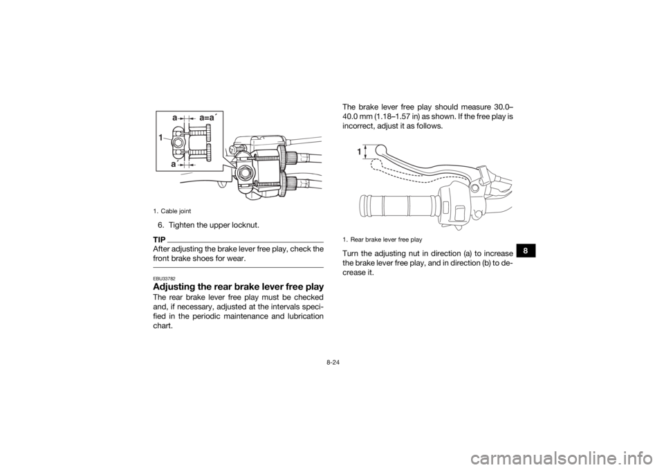
6. Tighten the upper locknut.
TIPAfter adjusting the brake lever free play, check the
front brake shoes for wear. EBU33782Adjusting the rear brake lever free playThe rear brake lever free play must be checked
and, if necessary, adjusted at the intervals speci-
fied in the periodic maintenance and lubrication
chart. The brake lever free play should measure 30.0–
40.0 mm (1.18–1.57 in) as shown. If the free play is
incorrect, adjust it as follows.
Turn the adjusting nut in direction (a) to increase
the brake lever free play, and in direction (b) to de-
crease it.1. Cable joint1
aa´
a=a´
1. Rear brake lever free play
1
UBD362E0.book Page 24 Tuesday, January 31, 2017 5:10 PM
Page 108 of 132
8-25
8
TIPAfter adjusting the brake lever free play, check the
rear brake shoes for wear. EBU34014Drive chain slackThe drive chain slack should be checked before
each ride and adjusted if necessary.TIPWhen checking and adjusting the drive chain
slack, there should be no weight on the ATV and
all tires must be touching the ground.
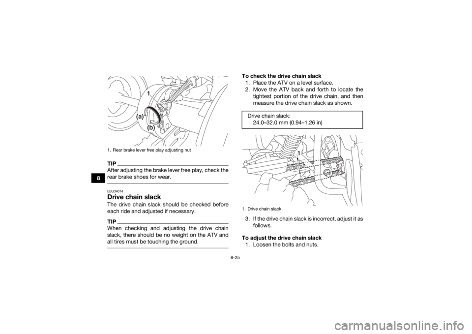
To check the drive chain slack1. Place the ATV on a level surface.
2. Move the ATV back and forth to locate the tightest portion of the drive chain, and then
measure the drive chain slack as shown.
3. If the drive chain slack is incorrect, adjust it as follows.
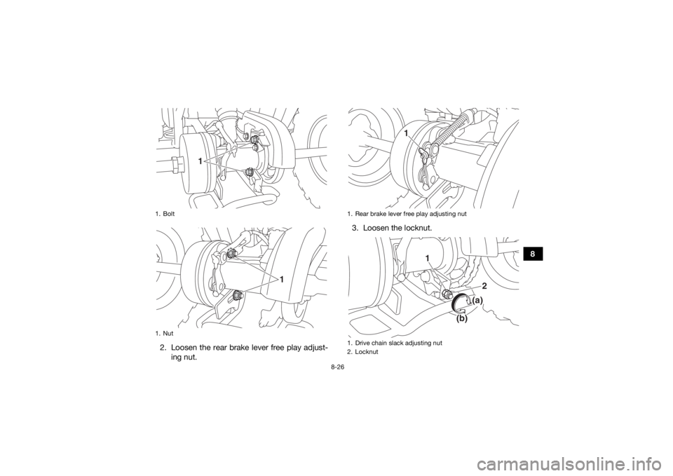
To adjust the drive chain slack 1. Loosen the bolts and nuts.
1. Rear brake lever free play adjusting nut
1
(a)
(b)
Drive chain slack: 24.0–32.0 mm (0.94–1.26 in)1. Drive chain slack
1
UBD362E0.book Page 25 Tuesday, January 31, 2017 5:10 PM
Page 109 of 132
8-26
8
2. Loosen the rear brake lever free play adjust- ing nut. 3. Loosen the locknut.
1. Bolt
1. Nut
1
1
1. Rear brake lever free play adjusting nut
1. Drive chain slack adjusting nut
2. Locknut
1
1
2
(a)
(b)
UBD362E0.book Page 26 Tuesday, January 31, 2017 5:10 PM
Page 110 of 132
8-27
84. To tighten the drive chain, turn the drive chain
slack adjusting nut in direction (a). To loosen
the drive chain, turn the adjusting nut in direc-
tion (b) and push the rear wheels forward.
NOTICE: Improper drive chain slack will
overload the engine as well as other vital
parts of the ATV and can lead to drive
chain slippage or breakage. To prevent
this from occurring, keep the drive chain
slack within the specified limits.
[ECB00543]
5. Tighten the locknut, and then the bolts and nuts to their specified torques.
6. Adjust the rear brake lever free play. (See page 8-24.)
EBU24883Lubricating the drive chainThe drive chain must be cleaned and lubricated at
the intervals specified in the periodic maintenance
and lubrication chart, otherwise it will quickly wear
out, especially when riding in dusty or wet areas.
Service the drive chain as follows.NOTICEECB00562The drive chain must be lubricated after wash-
ing the ATV or riding in the rain or wet areas. 1. Clean the drive chain with kerosene and asmall soft brush. NOTICE: To prevent dam-
aging the O-rings, do not clean the drive
chain with steam cleaners, high-pressure
washers or inappropriate solvents.
[ECB00572]
Tightening torques: Locknut:22 N·m (2.2 kgf·m, 16 lb·ft)
Bolt: 45 N·m (4.5 kgf·m, 33 lb·ft)
Nut: 54 N·m (5.4 kgf·m, 40 lb·ft)
UBD362E0.book Page 27 Tuesday, January 31, 2017 5:10 PM
Page 112 of 132
8-29
8
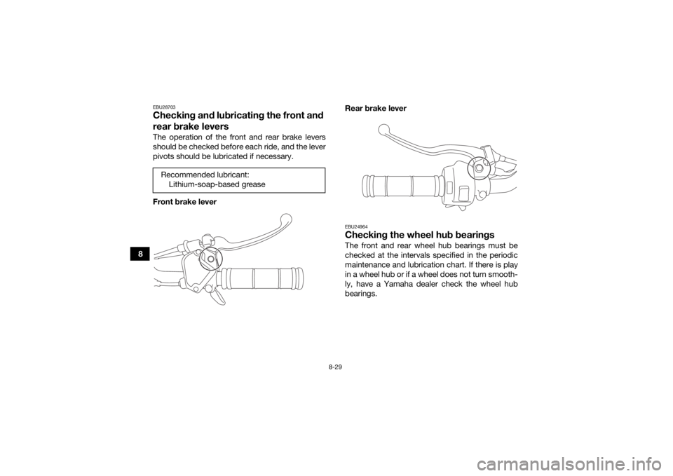
EBU28703Checking and lubricating the front and
rear brake leversThe operation of the front and rear brake levers
should be checked before each ride, and the lever
pivots should be lubricated if necessary.
Front brake leverRear brake lever
EBU24964Checking the wheel hub bearingsThe front and rear wheel hub bearings must be
checked at the intervals specified in the periodic
maintenance and lubrication chart. If there is play
in a wheel hub or if a wheel does not turn smooth-
ly, have a Yamaha dealer check the wheel hub
bearings.
Recommended lubricant:
Lithium-soap-based grease
UBD362E0.book Page 29 Tuesday, January 31, 2017 5:10 PM
Page 121 of 132
9-1
9
EBU25861
CLEANING AND STORAGE
EBU25903CleaningFrequent, thorough cleaning of your ATV will not
only enhance its appearance but will improve its
general performance and extend the useful life of
many components.1. Before cleaning the ATV: a. Block off the end of the exhaust pipe toprevent water entry. A plastic bag and
strong rubber band may be used.
b. Make sure the spark plug and all filler caps are properly installed.
2. If the engine case is excessively greasy, apply degreaser with a paint brush. Do not apply
degreaser to the chain, sprockets or wheel
axles.
3. Rinse the dirt and degreaser off with a garden hose. Use only enough pressure to do the
job. WARNING! Wet brakes may have re-
duced stopping ability, increasing the
chance of an accident. Test the brakes af-
ter washing. Apply the brakes several
times at slow speeds to let friction dry out
the linings.
[EWB02312]
NOTICE: Excessive wa- ter pressure may cause water seepage
and deterioration of wheel bearings,
brakes, transmission seals and electrical
devices. Many expensive repair bills have
resulted from improper high-pressure de-
tergent applications such as those avail-
able in coin-operated car washers.
[ECB00712]
4. Once most of the dirt has been hosed off,
wash all surfaces with warm water and mild,
detergent-type soap. An old toothbrush or
bottle brush is handy for hard-to-reach pla-
ces.
5. Rinse the ATV off immediately with clean wa- ter and dry all surfaces with a chamois, clean
towel or soft absorbing cloth.
6. Dry the chain and lubricate it to prevent it from rusting.
7. Clean the seat with a vinyl upholstery cleaner to keep the cover pliable and glossy.
8. Automotive type wax may be applied to all painted and chrome plated surfaces. Avoid
combination cleaner-waxes. Many contain
UBD362E0.book Page 1 Tuesday, January 31, 2017 5:10 PM
Page 126 of 132
10-3
10
Caster angle:3.40 °
Trail: 19.8 mm (0.78 in)Front tire:Type:Tubeless
Size: AT18 x 7-8
Manufacturer/model:
DURO/DI2017Rear tire:Type:Tubeless
Size:
AT18 x 9-8
Manufacturer/model: DURO/DI2016Loading:Maximum loading limit:
82.0 kg (181 lb)
(Total weight of rider, cargo, accessories, and tongue)Tire air pressure (measured on cold tires):Recommended:Front:
24.0 kPa (0.240 kgf/cm², 3.5 psi)
Rear: 24.0 kPa (0.240 kgf/cm², 3.5 psi)
Minimum: Front: 20.7 kPa (0.207 kgf/cm², 3.0 psi) Rear:
20.7 kPa (0.207 kgf/cm², 3.0 psi)
Front wheel:Wheel type:
Panel wheel
Rim size: 8 x 5.5ATRear wheel:Wheel type:
Panel wheel
Rim size: 8 x 5.5ATFront brake:Type:
Mechanical leading, trailing drum brake
Operation: Right hand operationRear brake:Type:
Mechanical leading, trailing drum brake
Operation: Left hand operationFront suspension:Type:
Swing axle
Spring/shock absorber type: Coil spring/oil damper
Wheel travel: 126 mm (5.0 in)
UBD362E0.book Page 3 Tuesday, January 31, 2017 5:10 PM
Page 130 of 132
12-1
12
INDEX
AAccessories and loading ................................................ 6-6
Air filter element, cleaning ............................................ 8-15BBattery .......................................................................... 8-31
Brake lever free play, adjusting the front ..................... 8-22
Brake lever free play (rear), adjusting ........................... 8-24
Brake lever, front ............................................................ 4-4
Brake lever, rear ............................................................. 4-5
Brake levers, checking and lubricating ........................ 8-29
Brakes .......................................................................... 8-21
Brakes, front and rear .................................................... 5-3CCables, checking and lubricating ................................. 8-28
Carburetor, adjusting ...................................................8-19
Chassis fasteners ........................................................... 5-6
Cleaning ......................................................................... 9-1DDrive chain ..................................................................... 5-3
Drive chain, lubricating ................................................ 8-27
Drive chain slack .......................................................... 8-25
Drive select lever ............................................................ 4-6
Drive select lever and driving in reverse ........................ 6-3EEngine break-in .............................................................. 6-4
Engine, cold start ........................................................... 6-1
Engine idling speed ...................................................... 8-19
Engine oil .............................................................. 5-3, 8-11
Engine, starting a warm ................................................. 6-3Engine stop switch ......................................................... 4-2
FFront and rear brake shoes, checking ......................... 8-21
Front knuckle pivots, lubricating .................................. 8-30
Fuel ........................................................................ 4-8, 5-3
Fuel cock ...................................................................... 4-10
Fuel tank cap ................................................................. 4-8
Fuse, replacing ............................................................. 8-34HHandlebar switches ....................................................... 4-2IIdentification numbers ................................................. 11-1
Indicator lights ............................................................... 4-1
Instruments and switches .............................................. 5-6KKickstarter ...................................................................... 4-7LLabel locations ............................................................... 1-1MMain switch .................................................................... 4-1
Maintenance and lubrication chart ................................ 8-5
Maintenance chart, emission control system ................ 8-3
Model label .................................................................. 11-1NNeutral indicator light ..................................................... 4-1OOwner’s manual and tool kit .......................................... 8-2PParking ........................................................................... 6-5
UBD362E0.book Page 1 Tuesday, January 31, 2017 5:10 PM
Page 131 of 132
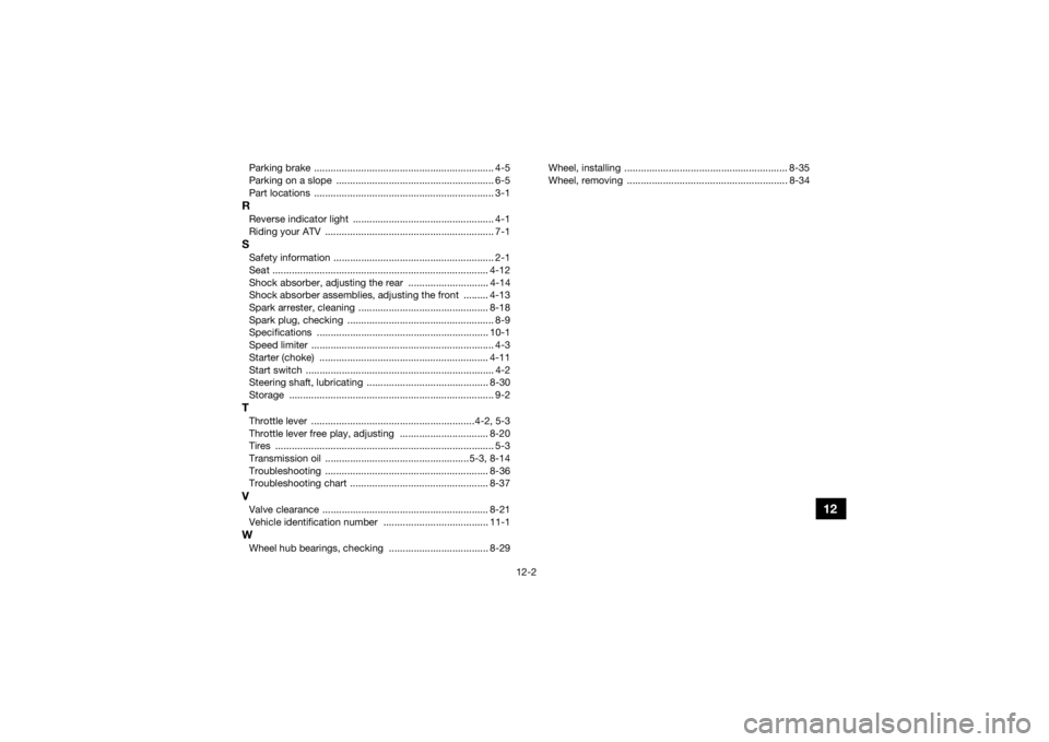
12-2
12
Parking brake ................................................................. 4-5
Parking on a slope ......................................................... 6-5
Part locations ................................................................. 3-1RReverse indicator light ................................................... 4-1
Riding your ATV ............................................................. 7-1SSafety information .......................................................... 2-1
Seat .............................................................................. 4-12
Shock absorber, adjusting the rear ............................. 4-14
Shock absorber assemblies, adjusting the front ......... 4-13
Spark arrester, cleaning ............................................... 8-18
Spark plug, checking ..................................................... 8-9
Specifications .............................................................. 10-1
Speed limiter .................................................................. 4-3
Starter (choke) ............................................................. 4-11
Start switch .................................................................... 4-2
Steering shaft, lubricating ............................................ 8-30
Storage .......................................................................... 9-2TThrottle lever ...........................................................4-2, 5-3
Throttle lever free play, adjusting ................................ 8-20
Tires ............................................................................... 5-3
Transmission oil ....................................................5-3, 8-14
Troubleshooting ........................................................... 8-36
Troubleshooting chart .................................................. 8-37VValve clearance ............................................................ 8-21
Vehicle identification number ...................................... 11-1WWheel hub bearings, checking .................................... 8-29Wheel, installing ........................................................... 8-35
Wheel, removing .......................................................... 8-34
UBD362E0.book Page 2 Tuesday, January 31, 2017 5:10 PM