Speed limiter YAMAHA YFM90R 2020 Owners Manual
[x] Cancel search | Manufacturer: YAMAHA, Model Year: 2020, Model line: YFM90R, Model: YAMAHA YFM90R 2020Pages: 126, PDF Size: 5.66 MB
Page 6 of 126

Your ATV was delivered with an adjustable speed limiter. Yamaha recommends that all beginners start off
to limit the amount of speed available while they learn. The adjusting screw may be gradually turned out
as the beginner becomes more familiar with operating the ATV. Parents should decide when to adjust the
ATV for more power as their youngster’s riding skills improve. Once the ATV rider can operate with skill at
the top speed permitted by adjusting the vehicle speed limiter alone, the engine speed limiter plate can be
removed. Since removal of this limiter will result in a significant increase in power, turn the vehicle speed
limiter adjusting screw completely back in again; adjust it out in stages as done previously.
If your child is a beginner or is inexperienced, he or she should take a training course.UBD364E0.book Page 2 Monday, January 28, 2019 9:30 AM
Page 9 of 126

EBU17421
TABLE OF CONTENTS
LOCATION OF THE WARNING AND
SPECIFICATION LABELS .............................. 1-1
SAFETY INFORMATION ................................ 2-1
DESCRIPTION................................................ 3-1Left view ...................................................... 3-1
Right view.................................................... 3-1
Controls and instruments............................ 3-2
INSTRUMENT AND CONTROL
FUNCTIONS ................................................... 4-1 Main switch ................................................. 4-1
Indicator lights............................................. 4-1
Handlebar switches .................................... 4-2
Throttle lever ............................................... 4-2
Speed limiter ............................................... 4-3
Front brake lever ......................................... 4-5
Rear brake lever .......................................... 4-5
Parking brake .............................................. 4-5
Drive select lever ......................................... 4-6
Kickstarter ................................................... 4-7
Fuel tank cap .............................................. 4-8
Fuel ............................................................. 4-9 Fuel cock .................................................. 4-10
Starter (choke) ......................................... 4-12
Seat .......................................................... 4-13
Front shock absorbers ............................. 4-13
Rear shock absorber ................................ 4-15
PRE-OPERATION CHECKS .......................... 5-1 Fuel ............................................................. 5-3
Engine oil .................................................... 5-3
Transmission .............................................. 5-3
Front and rear brakes ................................. 5-3
Throttle lever ............................................... 5-3
Drive chain .................................................. 5-3
Tires ............................................................ 5-3
Chassis fasteners ....................................... 5-6
Instruments and switches........................... 5-6
OPERATION .................................................. 6-1 Starting a cold engine................................. 6-1
Starting a warm engine............................... 6-3
Operating the drive select lever and driving in reverse ...................................... 6-3
Engine break-in........................................... 6-4
Parking........................................................ 6-5UBD364E0.book Page 1 Monday, January 28, 2019 9:30 AM
Page 28 of 126

4-3
4
EBU33802Speed limiterYour ATV was delivered with two speed limiter de-
vices. A vehicle speed limiter adjusting screw and
a removable engine speed limiter plate. Yamaha
recommends that all beginning riders start off with
the vehicle speed limiter adjusting screw fully
turned in and the engine speed limiter plate in-
stalled to limit the amount of speed available while
they learn.
The vehicle speed limiter keeps the throttle from
fully opening, even when the throttle lever is
pushed to the maximum. The adjusting screw may
be gradually turned out as the beginner becomes
more familiar with operating the ATV. Parents
should decide when to adjust the ATV for more
power as their youngster’s riding skills improve.
Once the ATV rider can operate with skill at the top
speed permitted by adjusting the vehicle speed
limiter alone, the engine speed limiter plate can be
removed. Since removal of this plate will result in
a significant increase in power, turn the vehicle
speed limiter adjusting screw completely back in
again and adjust it out in stages as done previous-
ly.Vehicle speed limiter
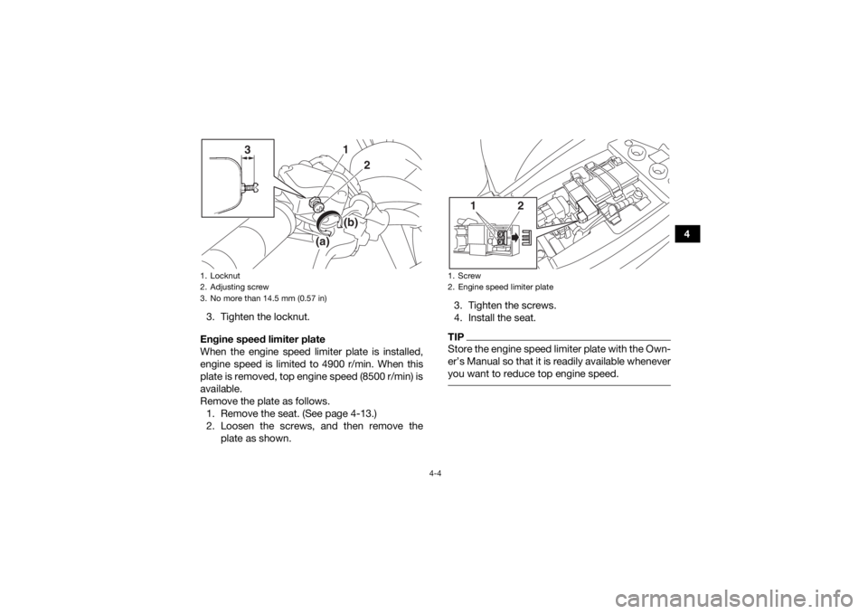
1. Loosen the locknut.
2. To increase the maximum engine power available and the maximum speed of the ATV,
turn the adjusting screw in direction (a). To
decrease the maximum engine power avail-
able and the maximum speed of the ATV, turn
the adjusting screw in direction (b). Do not
turn the adjusting screw out more than 14.5
mm (0.57 in) or the throttle cable could be
damaged. Always make sure the throttle lever
free play is adjusted to 1.5–4.0 mm (0.06–
0.16 in). (See page 8-20.) WARNING! Im-
proper adjustment of the speed limiter and
throttle could cause throttle cable damage
or improper throttle operation. You could
lose control, resulting in an accident.
[EWB00242]
UBD364E0.book Page 3 Monday, January 28, 2019 9:30 AM
Page 29 of 126
4-4
4
3. Tighten the locknut.
Engine speed limiter plate
When the engine speed limiter plate is installed,
engine speed is limited to 4900 r/min. When this
plate is removed, top engine speed (8500 r/min) is
available.
Remove the plate as follows. 1. Remove the seat. (See page 4-13.)
2. Loosen the screws, and then remove the plate as shown. 3. Tighten the screws.
4. Install the seat.
TIPStore the engine speed limiter plate with the Own-
er’s Manual so that it is readily available whenever
you want to reduce top engine speed.
1. Locknut
2. Adjusting screw
3. No more than 14.5 mm (0.57 in)
1
3
2
(b)
(a)
1. Screw
2. Engine speed limiter plate
12
UBD364E0.book Page 4 Monday, January 28, 2019 9:30 AM
Page 60 of 126
7-5
7Pre-operation checks
Always inspect your ATV before use to make sure
that it is safe operating condition. Perform the pre-
operation checks listed on page 5-1. Follow the
maintenance schedules and procedures as de-
scribed in the “Periodic Maintenance and Adjust-
ment” section of this manual.
WARNING! Failure
to inspect the ATV before riding it or failure to
maintain it properly increases the possibility of
an accident and equipment damage.
[EWB01433]
Speed limiter
For beginning riders, riders less experienced with
this model, or whenever limited speed is desir-
able, the throttle lever housing is equipped with a vehicle speed limiter. The speed limiter keeps the
throttle from fully opening, even when the throttle
lever is pushed to the maximum. Turning in the
adjusting screw limits the maximum engine power
available and decreases the maximum speed of
the ATV. Turning in the adjusting screw decreases
top speed, and turning it out increases top speed.
(See page 4-3.)
This model also has an engine speed limiter plate
to limit the amount of engine power available.
Yamaha recommends that all beginning riders start off with the engine speed limiter plate in-
stalled and the vehicle speed limiter adjusting
screw turned in to limit the amount of speed avail-
able while they learn. The vehicle speed limiter
may be gradually adjusted to increase maximum
speed as the beginner becomes more familiar with
operating the ATV. Parents should decide when to
adjust the ATV for more power as their young-
ster’s riding skills improve. Once the ATV rider can
operate with skill at the top speed permitted by
adjusting the vehicle speed limiter alone, the en-
gine speed limiter plate can be removed. Since re-
moval of this plate will result in a significant
increase in power, turn the vehicle speed limiterUBD364E0.book Page 5 Monday, January 28, 2019 9:30 AM
Page 61 of 126
7-6
7
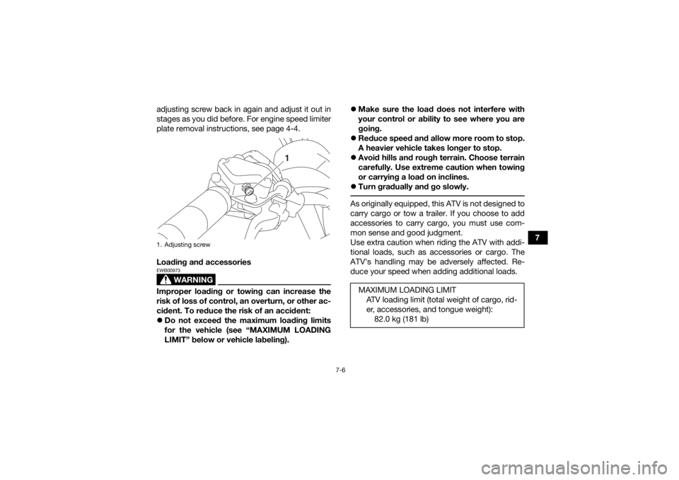
adjusting screw back in again and adjust it out in
stages as you did before. For engine speed limiter
plate removal instructions, see page 4-4.
Loading and accessories
WARNING
EWB00973Improper loading or towing can increase the
risk of loss of control, an overturn, or other ac-
cident. To reduce the risk of an accident:
Do not exceed the maximum loading limits
for the vehicle (see “MAXIMUM LOADING
LIMIT” below or vehicle labeling).
Make sure the load does not interfere with
your control or ability to see where you are
going.
Reduce speed and allow more room to stop.
A heavier vehicle takes longer to stop.
Avoid hills and rough terrain. Choose terrain
carefully. Use extreme caution when towing
or carrying a load on inclines.
Turn gradually and go slowly.
As originally equipped, this ATV is not designed to
carry cargo or tow a trailer. If you choose to add
accessories to carry cargo, you must use com-
mon sense and good judgment.
Use extra caution when riding the ATV with addi-
tional loads, such as accessories or cargo. The
ATV’s handling may be adversely affected. Re-
duce your speed when adding additional loads.
1. Adjusting screw
1
MAXIMUM LOADING LIMIT
ATV loading limit (total weight of cargo, rid-
er, accessories, and tongue weight):82.0 kg (181 lb)
UBD364E0.book Page 6 Monday, January 28, 2019 9:30 AM
Page 125 of 126

12-2
12
PParking ........................................................................... 6-5
Parking brake ................................................................. 4-5
Parking on a slope ......................................................... 6-5
Part locations ................................................................. 3-1RReverse indicator light ................................................... 4-1
Riding your ATV ............................................................. 7-1SSafety information .......................................................... 2-1
Seat .............................................................................. 4-13
Shock absorber, rear ................................................... 4-15
Shock absorbers, front ................................................ 4-13
Spark arrester, cleaning ............................................... 8-18
Spark plug, checking ..................................................... 8-9
Specifications .............................................................. 10-1
Speed limiter .................................................................. 4-3
Starter (choke) ............................................................. 4-12
Start switch .................................................................... 4-2
Steering shaft, lubricating ............................................ 8-31
Storage .......................................................................... 9-2TThrottle lever ...........................................................4-2, 5-3
Throttle lever free play, adjusting ................................ 8-20
Tires ............................................................................... 5-3
Transmission .................................................................. 5-3
Transmission oil ........................................................... 8-14
Troubleshooting ........................................................... 8-36
Troubleshooting chart .................................................. 8-37VValve clearance ............................................................ 8-21Vehicle identification number ...................................... 11-1
WWheel hub bearings, checking .................................... 8-29
Wheel, installing ........................................................... 8-35
Wheel, removing .......................................................... 8-35YYamalube ..................................................................... 8-13
UBD364E0.book Page 2 Monday, January 28, 2019 9:30 AM