warning YAMAHA YFZ450R 2013 Owners Manual
[x] Cancel search | Manufacturer: YAMAHA, Model Year: 2013, Model line: YFZ450R, Model: YAMAHA YFZ450R 2013Pages: 156, PDF Size: 3.75 MB
Page 3 of 156
READ THIS MANUAL CAREFULLY!
It contains important safety information.
WARNING
OWNER’S MANUAL
YFZ450RD
YFZ450RSED
This ATV should not be ridden by anyone under 16 years of age.
18P-28199-67-E0
U18P67E0.book Page 1 Wednesday, May 9, 2012 3:30 PM
Page 5 of 156

EBU17170
INTRODUCTION
EBU17322Congratulations on your purchase of the Yamaha YFZ450RD/YFZ450RSED. This ATV represents the re-
sult of many years of Yamaha experience in the production of fine sporting, touring, and pacesetting racing
machines. With the purchase of this Yamaha, you can now appreciate the high degree of craftsmanship
and reliability that have made Yamaha a leader in these fields.
This manual will provide you with a good basic understanding of the features and operation of this ATV.
This manual includes important safety information. It provides information about special tech-
niques and skills necessary to ride the ATV. It also includes basic maintenance and inspection proce-
dures. If you have any questions regarding the operation or maintenance of your ATV, please consult a
Yamaha dealer.
AN IMPORTANT SAFETY MESSAGE:●Read this manual completely before operating your ATV. Make sure you understand all instructions.●Pay close attention to the warning and notice labels on the ATV.●This ATV should not be ridden by anyone under 16 years of age.●This ATV is a high-performance ATV for off-road use only, for sport-type recreational and competitive use
by experienced operators.
U18P67E0.book Page 1 Wednesday, May 9, 2012 3:30 PM
Page 6 of 156
EBU17330
IMPORTANT MANUAL INFORMATION
EBU17342FAILURE TO FOLLOW THE WARNINGS CONTAINED IN THIS MANUAL CAN RESULT IN SERIOUS IN-
JURY OR DEATH.
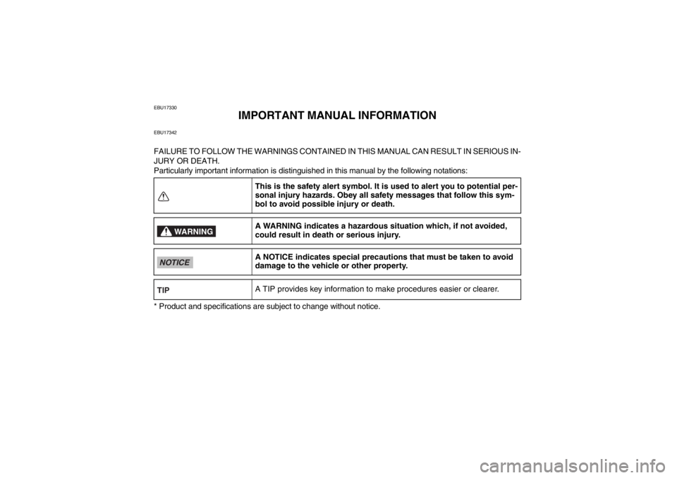
Particularly important information is distinguished in this manual by the following notations:
* Product and specifications are subject to change without notice.This is the safety alert symbol. It is used to alert you to potential per-
sonal injury hazards. Obey all safety messages that follow this sym-
bol to avoid possible injury or death.
A WARNING indicates a hazardous si
tuation which, if not avoided,
could result in death or serious injury.
A NOTICE indicates special precautions that must be taken to avoid
damage to the vehicle or other property.
A TIP provides key information to make procedures easier or clearer.
WARNING
NOTICETIPU18P67E0.book Page 1 Wednesday, May 9, 2012 3:30 PM
Page 8 of 156

EBU17420
TABLE OF CONTENTS
LOCATION OF THE WARNING AND
SPECIFICATION LABELS ............................ 1-1
SAFETY INFORMATION .............................. 2-1
DESCRIPTION .............................................. 3-1Left view ...................................................... 3-1
Right view.................................................... 3-1
Controls and instruments ............................ 3-2
INSTRUMENT AND CONTROL
FUNCTIONS .................................................. 4-1 Main switch ................................................ 4-1
Indicator light and warning lights ................ 4-2
Handlebar switches .................................... 4-3
Throttle lever .............................................. 4-4
Speed limiter .............................................. 4-5
Clutch lever ................................................ 4-5
Brake lever ................................................. 4-6
Brake pedal ................................................ 4-6
Parking brake lever .................................... 4-7
Shift pedal .................................................. 4-8
Fuel tank cap .............................................. 4-8
Fuel ............................................................ 4-9 Seat ..........................................................4-10
Adjusting the front shock absorber
assemblies ..............................................4-11
Adjusting the rear shock absorber assembly .................................................4-16
Handlebar position ....................................4-24
PRE-OPERATION CHECKS ..........................5-1 Fuel .............................................................5-4
Engine oil ....................................................5-4
Coolant .......................................................5-4
Front and rear brakes .................................5-4
Throttle lever ...............................................5-5
Drive chain ..................................................5-5
Tires ............................................................5-5
Chassis fasteners .......................................5-7
Instruments, lights and switches .................5-7
OPERATION...................................................6-1 Starting the engine ......................................6-1
Shifting ........................................................6-2
Engine break-in ...........................................6-4
Parking ........................................................6-4
Parking on a slope ......................................6-5U18P67E0.book Page 1 Wednesday, May 9, 2012 3:30 PM
Page 11 of 156
1-1
1
EBU29680
LOCATION OF THE WARNING AND SPECIFICATION LABELS
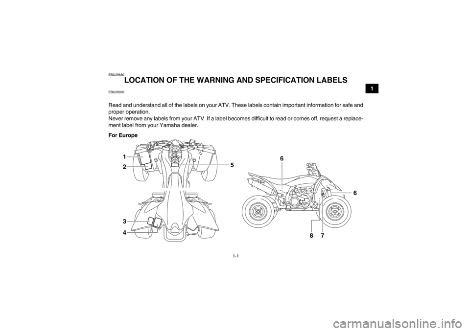
EBU29992Read and understand all of the labels on your ATV. These labels contain important information for safe and
proper operation.
Never remove any labels from your ATV. If a label becomes difficult to read or comes off, request a replace-
ment label from your Yamaha dealer.
For Europe
8
7
6
1
2
3
4
6
5
U18P67E0.book Page 1 Wednesday, May 9, 2012 3:30 PM
Page 19 of 156
1-9
1
4AA-22259-40
WARNING
OPERATING TIRE PRESSURE : Set with tires cold
Recommended
: Front
: 27.5
kPa
Rear
: 30.0
kPa
Minimum
: Front
: 24.5
kPa
Rear
: 27.0
kPa
Never set tire pressure below minimum.
It could cause the tire to dislodge from the rim.LOADINGMaximum weight capacity :
100 kg (220 lbs.)
Includes weight of operator, cargo and accessories.Improper tire pressure or overloading can cause
loss of control.
Loss of control can result in severe injury or
death.
4.0 psi
4.4 psi 3.6 psi
4.0 psi(
( )
() () )
5D3-2816M-00
WARNINGNEVER ride as a
passenger.Passengers can causea loss of control,resulting in SEVEREINJURY or DEATH.5FE-2151H-01
Use
97 octane
5TG-2415E-10
PREMIUM unleaded gasoline with min. (RON).
3
4 5
6
U18P67E0.book Page 9 Wednesday, May 9, 2012 3:30 PM
Page 25 of 156
2-6
2
WARNING
EWB00072Avoid Carbon Monoxide Poisoning
All engine exhaust contains carbon monoxide,
a deadly gas. Breathing carbon monoxide can
cause headaches, dizziness, drowsiness, nau-
sea, confusion, and eventually death.
Carbon Monoxide is a colorless, odorless,
tasteless gas which may be present even if you
do not see or smell any engine exhaust. Deadly
levels of carbon monoxide can collect rapidly
and you can quickly be overcome and unable
to save yourself. Also, deadly levels of carbon
monoxide can linger for hours or days in en-
closed or poorly ventilated areas. If you experi-
ence any symptoms of carbon monoxide
poisoning, leave the area immediately, get
fresh air, and SEEK MEDICAL TREATMENT.●Do not run engine indoors. Even if you try to
ventilate engine exhaust with fans or open
windows and doors, carbon monoxide can
rapidly reach dangerous levels.●Do not run engine in poorly ventilated or par-
tially enclosed areas such as barns, garages,
or carports.
●Do not run engine outdoors where engine
exhaust can be drawn into a building
through openings such as windows and
doors.
U18P67E0.book Page 6 Wednesday, May 9, 2012 3:30 PM
Page 29 of 156
4-2
4
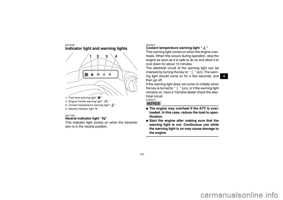
EBU29382Indicator light and warning lights EBU17860Neutral indicator light “ ”
This indicator light comes on when the transmis-
sion is in the neutral position.
EBU29921Coolant temperature warning light “ ”
This warning light comes on when the engine over-
heats. When this occurs during operation, stop the
engine as soon as it is safe to do so and allow it to
cool down for about 10 minutes.
The electrical circuit of the warning light can be
checked by turning the key to “ ” (on). The warn-
ing light should come on for a few seconds, and
then go off.
If the warning light does not come on initially when
the key is turned to “ ” (on), or if the warning light
remains on, have a Yamaha dealer check the elec-
trical circuit.NOTICEECB00010●The engine may overheat if the ATV is over-
loaded. In this case, reduce the load to spec-
ification.●Start the engine after making sure that the
warning light is out. Continuous use while
the warning light is on may cause damage to
the engine.
1. Fuel level warning light “ ”
2. Engine trouble warning light “ ”
3. Coolant temperature warning light “ ”
4. Neutral indicator light “N”
12 3 4
U18P67E0.book Page 2 Wednesday, May 9, 2012 3:30 PM
Page 30 of 156
4-3
4
EBU29931Fuel level warning light “ ”
This warning light comes on when the fuel level
drops below approximately 3.4 L (0.90 US gal,
0.75 Imp.gal). When this occurs, refuel as soon as
possible.
The electrical circuit of the warning light can be
checked by setting the engine stop switch to “ ”
and turning the key to “ ” (on). The warning light
should come on for a few seconds, and then go off.
If the warning light does not come on initially when
the key is turned to “ ” (on), or if the warning light
remains on, have a Yamaha dealer check the elec-
trical circuit.EBU29942Engine trouble warning light “ ”
This warning light comes on or flashes when an
electrical circuit monitoring the engine is not work-
ing correctly. When this occurs, have a Yamaha
dealer check the self-diagnosis system.
The electrical circuit of the warning light can be
checked by turning the key to “ ” (on). The warn-
ing light should come on for a few seconds, and
then go off.If the warning light does not come on initially when
the key is turned to “ ” (on), or if the warning light
remains on, have a Yamaha dealer check the elec-
trical circuit.
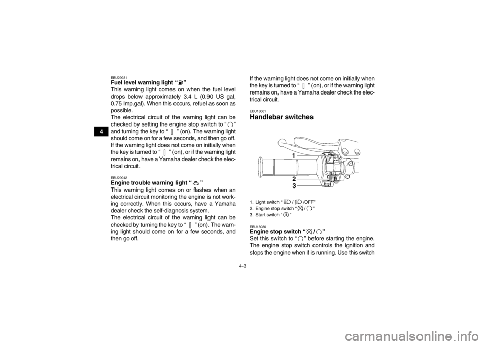
EBU18061Handlebar switches EBU18080Engine stop switch “ / ”
Set this switch to “ ” before starting the engine.
The engine stop switch controls the ignition and
stops the engine when it is running. Use this switch1. Light switch “ / /OFF”
2. Engine stop switch “ / ”
3. Start switch “ ”
1
23
U18P67E0.book Page 3 Wednesday, May 9, 2012 3:30 PM
Page 32 of 156
4-5
4
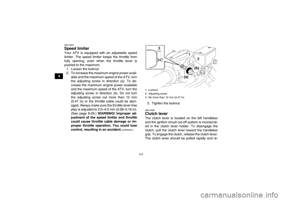
EBU18323Speed limiter Your ATV is equipped with an adjustable speed
limiter. The speed limiter keeps the throttle from
fully opening, even when the throttle lever is
pushed to the maximum.1. Loosen the locknut.
2. To increase the maximum engine power avail- able and the maximum speed of the ATV, turn
the adjusting screw in direction (a). To de-
crease the maximum engine power available
and the maximum speed of the ATV, turn the
adjusting screw in direction (b). Do not turn
the adjusting screw out more than 12 mm
(0.47 in) or the throttle cable could be dam-
aged. Always make sure the throttle lever free
play is adjusted to 2.0–4.0 mm (0.08–0.16 in).
(See page 8-29.) WARNING! Improper ad-
justment of the speed limiter and throttle
could cause throttle cable damage or im-
proper throttle operation. You could lose
control, resulting in an accident.
[EWB00241]
3. Tighten the locknut.EBU18382Clutch lever The clutch lever is located on the left handlebar
and the ignition circuit cut-off system is incorporat-
ed in the clutch lever holder. To disengage the
clutch, pull the clutch lever toward the handlebar
grip. To engage the clutch, release the clutch lever.
The clutch lever should be pulled rapidly and re-1. Locknut
2. Adjusting screw
3. No more than 12 mm (0.47 in)
3
12
(a)
(b)
U18P67E0.book Page 5 Wednesday, May 9, 2012 3:30 PM