check engine YAMAHA YFZ450R 2016 Owner's Manual
[x] Cancel search | Manufacturer: YAMAHA, Model Year: 2016, Model line: YFZ450R, Model: YAMAHA YFZ450R 2016Pages: 154, PDF Size: 3.8 MB
Page 114 of 154
8-25
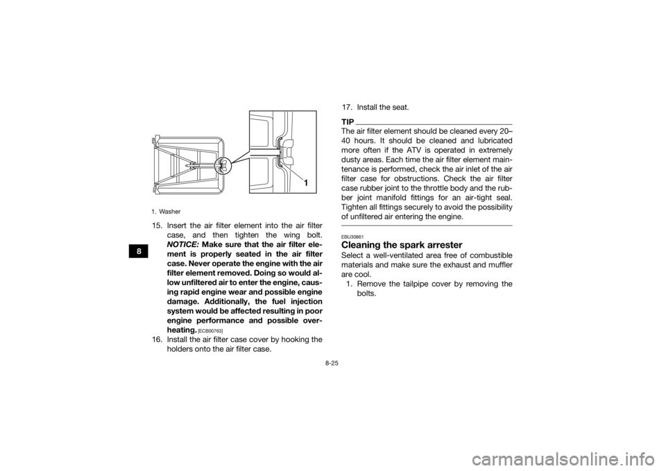
815. Insert the air filter element into the air filter
case, and then tighten the wing bolt.
NOTICE: Make sure that the air filter ele-
ment is properly seated in the air filter
case. Never operate the engine with the air
filter element removed. Doing so would al-
low unfiltered air to enter the engine, caus-
ing rapid engine wear and possible engine
damage. Additionally, the fuel injection
system would be affected resulting in poor
engine performance and possible over-
heating.
[ECB00763]
16. Install the air filter case cover by hooking the holders onto the air filter case. 17. Install the seat.
TIPThe air filter element should be cleaned every 20–
40 hours. It should be cleaned and lubricated
more often if the ATV is operated in extremely
dusty areas. Each time the air filter element main-
tenance is performed, check the air inlet of the air
filter case for obstructions. Check the air filter
case rubber joint to the throttle body and the rub-
ber joint manifold fittings for an air-tight seal.
Tighten all fittings securely to avoid the possibility
of unfiltered air entering the engine. EBU30861Cleaning the spark arresterSelect a well-ventilated area free of combustible
materials and make sure the exhaust and muffler
are cool.
1. Remove the tailpipe cover by removing the bolts.
1. Washer
1
U1TD62E0.book Page 25 Monday, May 18, 2015 9:20 AM
Page 116 of 154
8-27
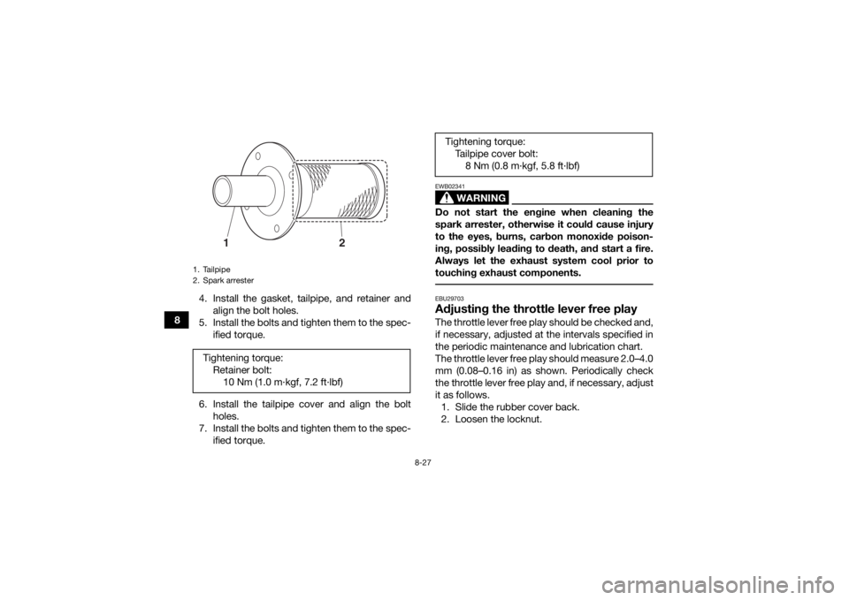
84. Install the gasket, tailpipe, and retainer and
align the bolt holes.
5. Install the bolts and tighten them to the spec- ified torque.
6. Install the tailpipe cover and align the bolt holes.
7. Install the bolts and tighten them to the spec- ified torque.
WARNING
EWB02341Do not start the engine when cleaning the
spark arrester, otherwise it could cause injury
to the eyes, burns, carbon monoxide poison-
ing, possibly leading to death, and start a fire.
Always let the exhaust system cool prior to
touching exhaust components. EBU29703Adjusting the throttle lever free playThe throttle lever free play should be checked and,
if necessary, adjusted at the intervals specified in
the periodic maintenance and lubrication chart.
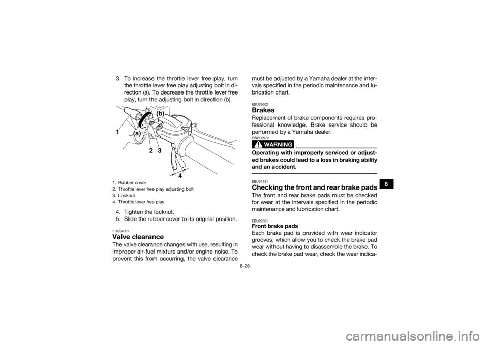
The throttle lever free play should measure 2.0–4.0
mm (0.08–0.16 in) as shown. Periodically check
the throttle lever free play and, if necessary, adjust
it as follows.1. Slide the rubber cover back.
2. Loosen the locknut.
1. Tailpipe
2. Spark arresterTightening torque: Retainer bolt:10 Nm (1.0 m·kgf, 7.2 ft·lbf)
1
2
Tightening torque:Tailpipe cover bolt:8 Nm (0.8 m·kgf, 5.8 ft·lbf)
U1TD62E0.book Page 27 Monday, May 18, 2015 9:20 AM
Page 117 of 154
8-28
8
3. To increase the throttle lever free play, turn
the throttle lever free play adjusting bolt in di-
rection (a). To decrease the throttle lever free
play, turn the adjusting bolt in direction (b).
4. Tighten the locknut.
5. Slide the rubber cover to its original position.
EBU24061Valve clearanceThe valve clearance changes with use, resulting in
improper air-fuel mixture and/or engine noise. To
prevent this from occurring, the valve clearance must be adjusted by a Yamaha dealer at the inter-
vals specified in the periodic maintenance and lu-
brication chart.
EBU29602BrakesReplacement of brake components requires pro-
fessional knowledge. Brake service should be
performed by a Yamaha dealer.
WARNING
EWB02572Operating with improperly serviced or adjust-
ed brakes could lead to a loss in braking ability
and an accident. EBU24131Checking the front and rear brake padsThe front and rear brake pads must be checked
for wear at the intervals specified in the periodic
maintenance and lubrication chart.EBU29561Front brake pads
Each brake pad is provided with wear indicator
grooves, which allow you to check the brake pad
wear without having to disassemble the brake. To
check the brake pad wear, check the wear indica-
1. Rubber cover
2. Throttle lever free play adjusting bolt
3. Locknut
4. Throttle lever free play
32
4
(a)(b)
1
U1TD62E0.book Page 28 Monday, May 18, 2015 9:20 AM
Page 127 of 154
8-38
8
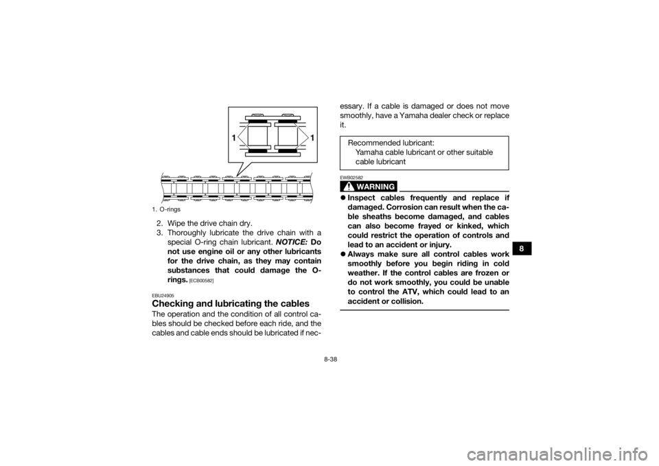
2. Wipe the drive chain dry.
3. Thoroughly lubricate the drive chain with a
special O-ring chain lubricant. NOTICE: Do
not use engine oil or any other lubricants
for the drive chain, as they may contain
substances that could damage the O-
rings.
[ECB00582]
EBU24905
Checking and lubricating the cablesThe operation and the condition of all control ca-
bles should be checked before each ride, and the
cables and cable ends should be lubricated if nec- essary. If a cable is damaged or does not move
smoothly, have a Yamaha dealer check or replace
it.
WARNING
EWB02582
Inspect cables frequently and replace if
damaged. Corrosion can result when the ca-
ble sheaths become damaged, and cables
can also become frayed or kinked, which
could restrict the operation of controls and
lead to an accident or injury.
Always make sure all control cables work
smoothly before you begin riding in cold
weather. If the control cables are frozen or
do not work smoothly, you could be unable
to control the ATV, which could lead to an
accident or collision.
1. O-rings
1
1
Recommended lubricant:
Yamaha cable lubricant or other suitable cable lubricant
U1TD62E0.book Page 38 Monday, May 18, 2015 9:20 AM
Page 140 of 154
8-51
8
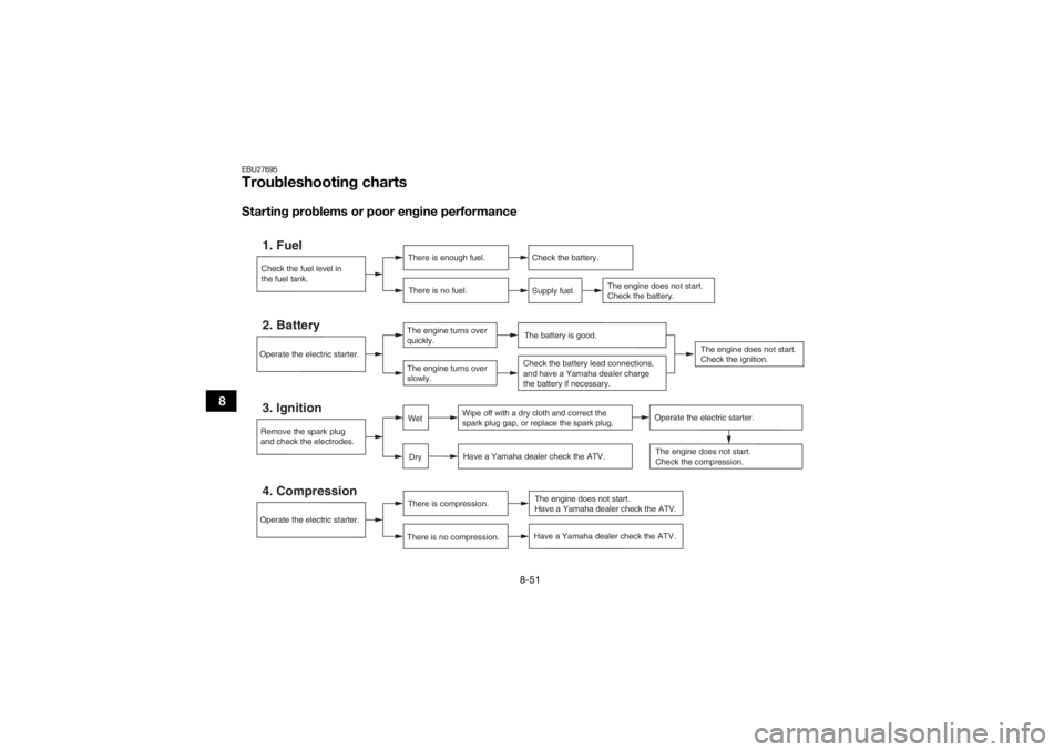
EBU27695Troubleshooting chartsStarting problems or poor engine performance
Check the fuel level in
the fuel tank.1. Fuel
There is enough fuel.There is no fuel.
Check the battery.
Supply fuel.
The engine does not start.
Check the battery.
Operate the electric starter.4. Compression
There is compression.
There is no compression.
The engine does not start.
Have a Yamaha dealer check the ATV.
Remove the spark plug
and check the electrodes.3. Ignition
Wipe off with a dry cloth and correct the
spark plug gap, or replace the spark plug. Have a Yamaha dealer check the ATV.
The engine does not start.
Check the compression.
DryWet
Operate the electric starter.
Have a Yamaha dealer check the ATV.
The engine does not start.
Check the ignition.
Operate the electric starter.2. Battery
The engine turns over
quickly.
The engine turns over
slowly.
The battery is good.Check the battery lead connections,
and have a Yamaha dealer charge
the battery if necessary.
U1TD62E0.book Page 51 Monday, May 18, 2015 9:20 AM
Page 141 of 154
8-52
8
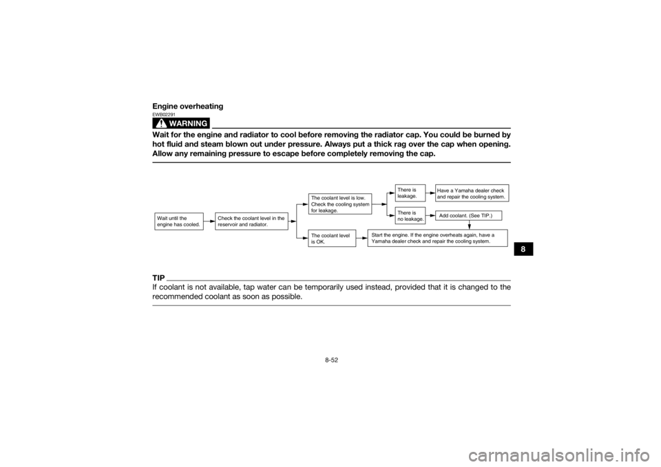
Engine overheating
WARNING
EWB02291Wait for the engine and radiator to cool before removing the radiator cap. You could be burned by
hot fluid and steam blown out under pressure. Always put a thick rag over the cap when opening.
Allow any remaining pressure to escape before completely removing the cap. TIPIf coolant is not available, tap water can be temporarily used instead, provided that it is changed to the
recommended coolant as soon as possible. Wait until the
engine has cooled.
Check the coolant level in the
reservoir and radiator.
The coolant level
is OK.The coolant level is low.
Check the cooling system
for leakage.
Have a Yamaha dealer check
and repair the cooling system.Add coolant. (See TIP.)
Start the engine. If the engine overheats again, have a
Yamaha dealer check and repair the cooling system.
There is
leakage.
There is
no leakage.
U1TD62E0.book Page 52 Monday, May 18, 2015 9:20 AM
Page 143 of 154

9-2
9
abrasives which may mar the paint or protec-
tive finish. When finished cleaning, start the
engine and let it idle for several minutes.
EBU27262StorageShort-term
Always store your ATV in a cool, dry place and, if
necessary, protect it against dust with a porous
cover.
NOTICE: Storing the ATV in a poorly ven-
tilated room or covering it with a tarp while it is
still wet, will allow water and humidity to seep
in and cause rust. To prevent corrosion, avoid
damp cellars, stables (because of the presence
of ammonia) and areas where strong chemi-
cals are stored.
[ECB00722]
Long-term
Before storing your ATV for several months: 1. Follow all the instructions in the “Cleaning” section of this chapter.
2. Fill up the fuel tank and add fuel stabilizer (if available) to prevent the fuel from deteriorat-
ing. 3. Perform the following steps to protect the cyl-
inder, piston rings, etc. from corrosion.a. Remove the spark plug cap and spark plug.
b. Pour a teaspoonful of engine oil into the spark plug bore.
c. Install the spark plug cap onto the spark plug, and then place the spark plug on the
cylinder head so that the electrodes are
grounded. (This will limit sparking during
the next step.)
d. Turn the engine over several times with the starter. (This will coat the cylinder wall
with oil.)
e. Remove the spark plug cap from the spark plug, and then install the spark plug and
the spark plug cap.
4. Lubricate all control cables and the pivoting points of all levers and pedals.
5. Check and, if necessary, correct the tire air pressure, and then block up the ATV so that
all of its wheels are off the ground. Alterna-
Specified amount:
7.5 ml of stabilizer to each liter of fuel (or 1
oz of stabilizer to each gallon of fuel)U1TD62E0.book Page 2 Monday, May 18, 2015 9:20 AM
Page 152 of 154

12-1
12
INDEX
AAccessories and loading ................................................ 6-5
Air filter element, cleaning ............................................ 8-21BBattery .......................................................................... 8-42
Brake and clutch levers, checking and lubricating ...... 8-39
Brake fluid, changing ...................................................8-31
Brake fluid level, checking ........................................... 8-29
Brake lever ..................................................................... 4-6
Brake lever free play, checking the front ..................... 8-31
Brake light switches ..................................................... 8-33
Brake pads, checking the front and rear ..................... 8-28
Brake pedal .................................................................... 4-6
Brake pedal, checking and lubricating ........................ 8-39
Brake pedal height, checking ...................................... 8-32
Brakes .......................................................................... 8-28
Brakes, front and rear .................................................... 5-4CCables, checking and lubricating ................................. 8-38
Chassis fasteners ........................................................... 5-7
Cleaning ......................................................................... 9-1
Clutch lever .................................................................... 4-5
Clutch lever free play, adjusting ................................... 8-34
Coolant ................................................................. 5-4, 8-20
Coolant temperature warning light ................................. 4-2
Cowling and panels, removing and installing .............. 8-10DDrive chain ..................................................................... 5-5
Drive chain, lubricating ................................................ 8-37 Drive chain slack .......................................................... 8-35
EEngine break-in .............................................................. 6-4
Engine oil ....................................................................... 5-4
Engine oil and oil filter element .................................... 8-14
Engine, start ................................................................... 6-1
Engine stop switch ......................................................... 4-3
Engine trouble warning light .......................................... 4-3FFuel ........................................................................ 4-9, 5-4
Fuel level warning light ................................................... 4-3
Fuel tank cap ................................................................. 4-8
Fuse, replacing ............................................................. 8-45HHandlebar position, adjusting ...................................... 4-24
Handlebar switches ....................................................... 4-3
Headlight beam, adjusting ........................................... 8-48
Headlight bulb, replacing ............................................. 8-45IIdentification numbers ................................................. 11-1
Indicator light and warning lights ................................... 4-2
Instruments, lights and switches ................................... 5-8LLabel locations ............................................................... 1-1
Light switch .................................................................... 4-4MMain switch .................................................................... 4-1
Maintenance and lubrication chart ................................ 8-5
Maintenance chart, emission control system ................ 8-3
U1TD62E0.book Page 1 Monday, May 18, 2015 9:20 AM