lock YAMAHA YFZ450R 2021 User Guide
[x] Cancel search | Manufacturer: YAMAHA, Model Year: 2021, Model line: YFZ450R, Model: YAMAHA YFZ450R 2021Pages: 150, PDF Size: 3.84 MB
Page 44 of 150
5-18
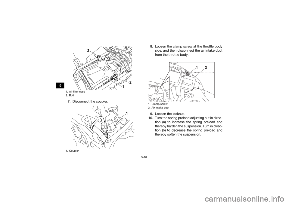
57. Disconnect the coupler. 8. Loosen the clamp screw at the throttle body
side, and then disconnect the air intake duct
from the throttle body.
9. Loosen the locknut.
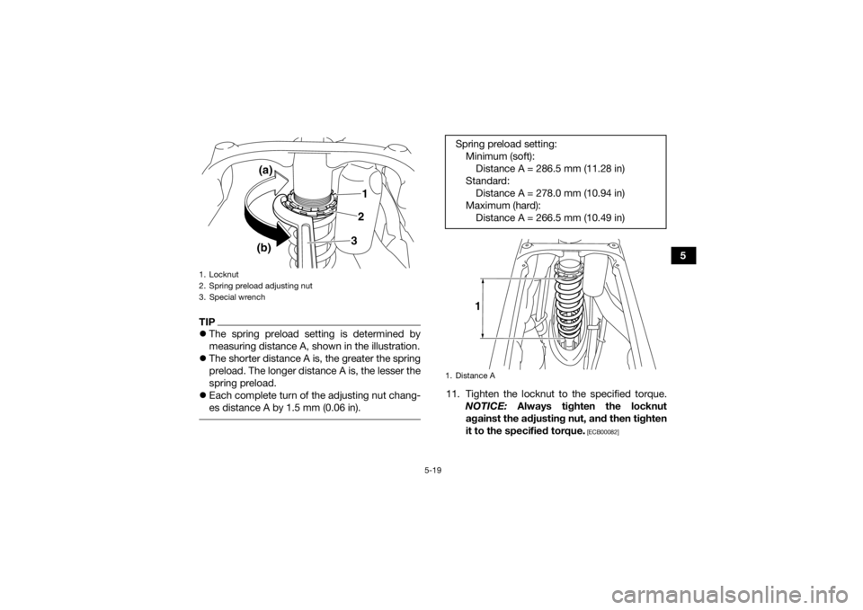
10. Turn the spring preload adjusting nut in direc- tion (a) to increase the spring preload and
thereby harden the suspension. Turn in direc-
tion (b) to decrease the spring preload and
thereby soften the suspension.
1. Air filter case
2. Bolt
1. Coupler
12
2
1
1. Clamp screw
2. Air intake duct
1
2
UBKD60E0.book Page 18 Wednesday, November 18, 2020 8:39 AM
Page 45 of 150
5-19
5
TIPThe spring preload setting is determined by
measuring distance A, shown in the illustration.
The shorter distance A is, the greater the spring
preload. The longer distance A is, the lesser the
spring preload.
Each complete turn of the adjusting nut chang-
es distance A by 1.5 mm (0.06 in).
11. Tighten the locknut to the specified torque.
NOTICE: Always tighten the locknut
against the adjusting nut, and then tighten
it to the specified torque.
[ECB00082]
1. Locknut
2. Spring preload adjusting nut
3. Special wrench
2 13
(a)
(b)
Spring preload setting: Minimum (soft):Distance A = 286.5 mm (11.28 in)
Standard: Distance A = 278.0 mm (10.94 in)
Maximum (hard): Distance A = 266.5 mm (10.49 in)1. Distance A
1
UBKD60E0.book Page 19 Wednesday, November 18, 2020 8:39 AM
Page 46 of 150

5-20
512. Connect the air intake duct to the throttle
body, and then tighten the clamp screw at the
throttle body side. NOTICE: Make sure that
the air intake duct is properly connected to
the throttle body, and that the clamp
screw is tightened securely.
[ECB00962]
13. Connect the coupler.
14. Connect the air filter case to the air intake duct, place the air filter case in the original po-
sition, and then tighten the clamp screw at
the air filter case side. NOTICE: Make sure
that the air intake duct is properly con-
nected to the air filter case, and that the
clamp screw is tightened securely.
[ECB00972]
15. Install the air filter case bolts, and then tighten them to the specified torque. 16. Install the air filter case holding plate by in-
stalling the bolts and collars, and then tighten
the bolts to the specified torque.
17. Install the blow-by gas chamber by installing the bolt, tighten the bolt to the specified
torque, and then install the clip to the hose
holder.
18. Install the cowling.
Rebound damping force
Turn the rebound damping force adjusting screw
in direction (a) to increase the rebound damping
force. Turn in direction (b) to decrease the re-
bound damping force.
Tightening torque:
Locknut:30 N·m (3.0 kgf·m, 22 lb·ft)
Tightening torque: Air filter case bolt:7 N·m (0.7 kgf·m, 5.2 lb·ft)
Tightening torque:Air filter case holding plate bolt:7 N·m (0.7 kgf·m, 5.2 lb·ft)
Tightening torque: Blow-by gas chamber bolt:7 N·m (0.7 kgf·m, 5.2 lb·ft)
UBKD60E0.book Page 20 Wednesday, November 18, 2020 8:39 AM
Page 61 of 150

7-5
7
EBU20907Parking on a slope
WARNING
EWB00852Avoid parking on hills or other inclines. Parking
on a hill or other incline could cause the ATV to
roll out of control, increasing the chance of an
accident. If you must park on an incline, place
the ATV transversely across the incline, shift
into first gear, stop the engine, apply the park-
ing brake, and then block the front and rear
wheels with rocks or other objects.Never park the ATV on hills that are too steep
to walk up easily.
1. Bring the ATV to a stop by applying the
brakes.
2. With the brake pedal applied, shift into first gear and then stop the engine.
3. Apply the parking brake.EBU20911Accessories and loadingEBU20922Genuine Yamaha Accessories
Choosing accessories for your ATV is an impor-
tant decision. Genuine Yamaha Accessories,
which are available only from a Yamaha dealer,
1. Parking brake lever (locked position)UBKD60E0.book Page 5 Wednesday, November 18, 2020 8:39 AM
Page 68 of 150

8-5
8Pre-operation checks
Always inspect your ATV each time you use it to
make sure the ATV is in safe operating condition.
Perform the pre-operation checks listed on page
6-1. Always follow the inspection and mainte-
nance procedures and schedules described in the
Owner’s Manual.
WARNING! Failure to inspect
the ATV before riding it or failure to maintain it
properly increases the possibility of an acci-
dent and equipment damage.
[EWB01433]
Speed limiter
For riders less experienced with this model, the
throttle lever housing is equipped with a speed
limiter. The speed limiter keeps the throttle from fully opening, even when the throttle lever is
pushed to the maximum. Turning in the adjusting
screw limits the maximum engine power available
and decreases the maximum speed of the ATV.
Turning in the adjusting screw decreases top
speed, and turning it out increases top speed.
(See page 5-4.)
Loading and accessories
WARNING
EWB00973Improper loading or towing can increase the
risk of loss of control, an overturn, or other ac-
cident. To reduce the risk of an accident:1. Adjusting screw
2. Locknut
2
1
UBKD60E0.book Page 5 Wednesday, November 18, 2020 8:39 AM
Page 78 of 150

8-15
8It is important when climbing a hill to make sure
that your weight is transferred forward on the ATV.
This can be accomplished by leaning forward and,
on steeper inclines, standing on the footrests and
leaning forward over the handlebars. Whenever
possible, ride straight up hills.
Slow down when you reach the crest of the hill if
you cannot see clearly what is on the other side –
there could be another person, an obstacle, or a
sharp drop-off. Use common sense and remem-
ber that some hills are too steep for you to climb
or descend.
If you are climbing a hill and you find that you have
not properly judged your ability to make it to the
top, you should turn the ATV around while you still
have forward motion (provided you have the room
to do so) and go down the hill.
If your ATV has stalled or stopped and you believe
you can continue up the hill, restart carefully to
make sure you do not lift the front wheels which
could cause you to lose control. If you are unable
to continue up the hill, dismount the ATV on the
uphill side. Physically turn the ATV around and
then descend the hill. If you start to roll backwards, DO NOT apply the
rear brake, and apply the front brake gradually.
The ATV could easily tip over backwards. When
fully stopped, apply the rear brake as well, and
then lock the parking brake. Dismount the ATV im-
mediately on the uphill side or to a side if pointed
straight uphill. Turn the ATV around and remount,
following the procedure described in the Owner’s
Manual.
WARNING! Stalling, rolling backwards
or improperly dismounting while climbing a hill
could result in ATV overturning. If you cannot
control the ATV, dismount immediately on the
uphill side.
[EWB01803]
UBKD60E0.book Page 15 Wednesday, November 18, 2020 8:39 AM
Page 95 of 150
9-10
9
EBU30131Removing and installing the cowling
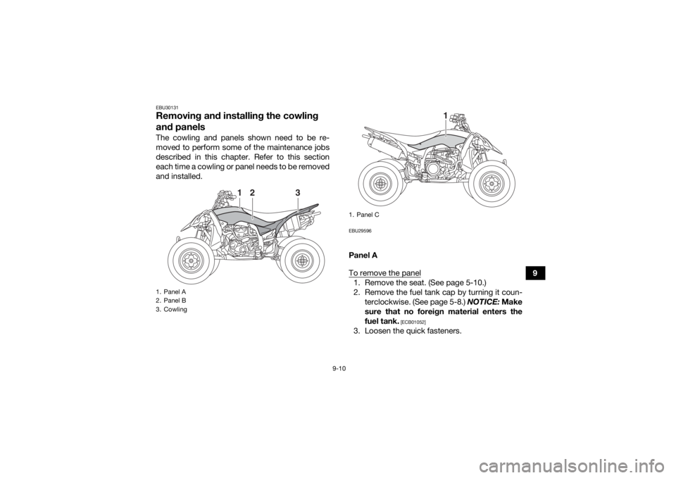
and panelsThe cowling and panels shown need to be re-
moved to perform some of the maintenance jobs
described in this chapter. Refer to this section
each time a cowling or panel needs to be removed
and installed.
EBU29596Panel A
To remove the panel1. Remove the seat. (See page 5-10.)
2. Remove the fuel tank cap by turning it coun-terclockwise. (See page 5-8.) NOTICE: Make
sure that no foreign material enters the
fuel tank.
[ECB01052]
3. Loosen the quick fasteners.
1. Panel A
2. Panel B
3. Cowling
1
2
3
1. Panel C
1
UBKD60E0.book Page 10 Wednesday, November 18, 2020 8:39 AM
Page 96 of 150
9-11
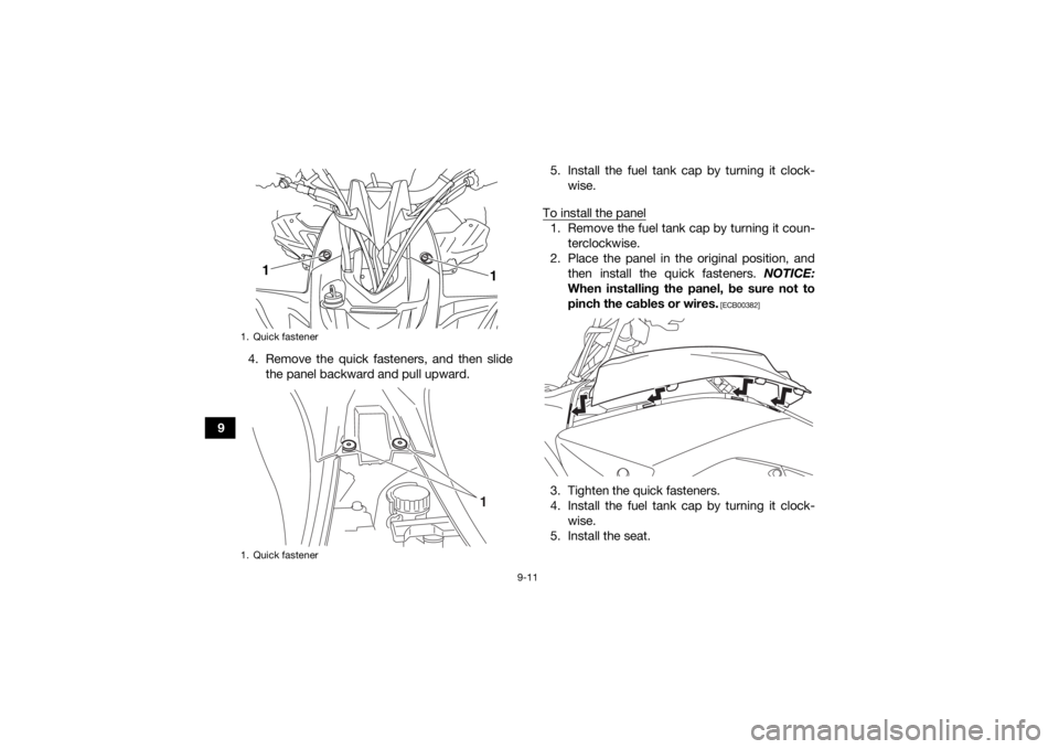
94. Remove the quick fasteners, and then slide
the panel backward and pull upward. 5. Install the fuel tank cap by turning it clock-
wise.
To install the panel
1. Remove the fuel tank cap by turning it coun- terclockwise.
2. Place the panel in the original position, and then install the quick fasteners. NOTICE:
When installing the panel, be sure not to
pinch the cables or wires.
[ECB00382]
3. Tighten the quick fasteners.
4. Install the fuel tank cap by turning it clock- wise.
5. Install the seat.
1. Quick fastener
1. Quick fastener
1 1
1
UBKD60E0.book Page 11 Wednesday, November 18, 2020 8:39 AM
Page 113 of 150

9-28
9
EBU29705Adjusting the throttle lever free playPeriodically check the throttle lever free play and
adjust if necessary.1. Slide the rubber cover back.
2. Loosen the locknut.
3. To increase the throttle lever free play, turn
the throttle lever free play adjusting bolt in di-
rection (a). To decrease the throttle lever free
play, turn the adjusting bolt in direction (b).
4. Tighten the locknut.
5. Slide the rubber cover to its original position.
EBU24062Valve clearanceThe valve clearance changes with use, resulting in
improper air-fuel mixture and/or engine noise. To
prevent this from occurring, the valve clearance
must be adjusted by a Yamaha dealer at the inter-
vals specified in the periodic maintenance chart.EBU29602BrakesReplacement of brake components requires pro-
fessional knowledge. Brake service should be
performed by a Yamaha dealer.
Tightening torque:
Tailpipe cover bolt:8 N·m (0.8 kgf·m, 5.9 lb·ft)
1. Rubber cover
2. Throttle lever free play adjusting bolt
3. Locknut
4. Throttle lever free playThrottle lever free play: 2.0–4.0 mm (0.08–0.16 in)
32
4
(a)(b)
1
UBKD60E0.book Page 28 Wednesday, November 18, 2020 8:39 AM
Page 116 of 150
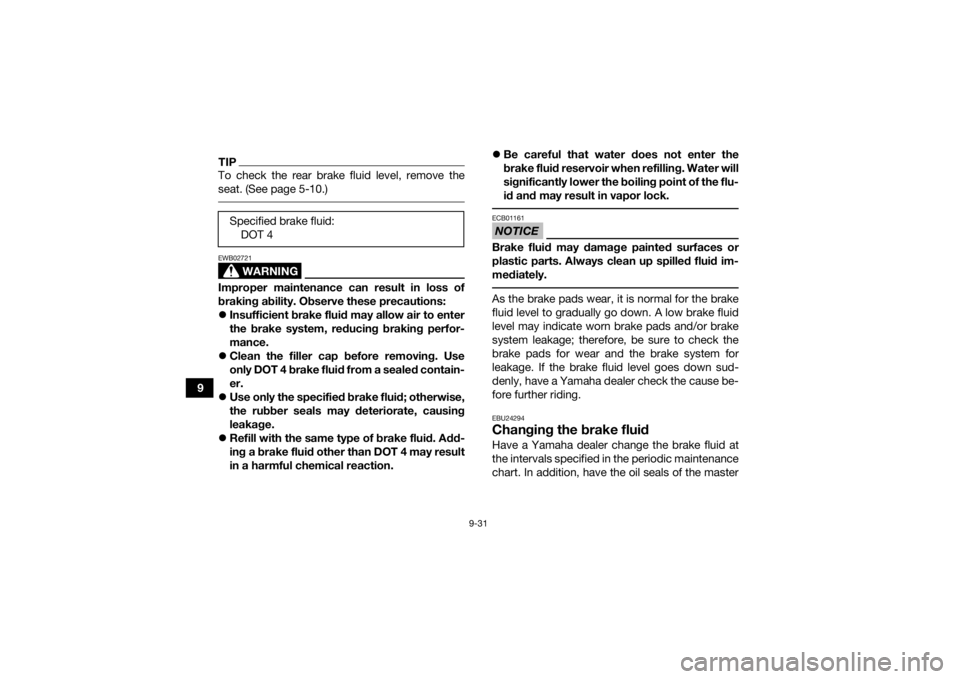
9-31
9
TIPTo check the rear brake fluid level, remove the
seat. (See page 5-10.)
WARNING
EWB02721Improper maintenance can result in loss of
braking ability. Observe these precautions:
Insufficient brake fluid may allow air to enter
the brake system, reducing braking perfor-
mance.
Clean the filler cap before removing. Use
only DOT 4 brake fluid from a sealed contain-
er.
Use only the specified brake fluid; otherwise,
the rubber seals may deteriorate, causing
leakage.
Refill with the same type of brake fluid. Add-
ing a brake fluid other than DOT 4 may result
in a harmful chemical reaction.
Be careful that water does not enter the
brake fluid reservoir when refilling. Water will
significantly lower the boiling point of the flu-
id and may result in vapor lock.
NOTICEECB01161Brake fluid may damage painted surfaces or
plastic parts. Always clean up spilled fluid im-
mediately. As the brake pads wear, it is normal for the brake
fluid level to gradually go down. A low brake fluid
level may indicate worn brake pads and/or brake
system leakage; therefore, be sure to check the
brake pads for wear and the brake system for
leakage. If the brake fluid level goes down sud-
denly, have a Yamaha dealer check the cause be-
fore further riding.EBU24294Changing the brake fluidHave a Yamaha dealer change the brake fluid at
the intervals specified in the periodic maintenance
chart. In addition, have the oil seals of the master
Specified brake fluid:
DOT 4
UBKD60E0.book Page 31 Wednesday, November 18, 2020 8:39 AM