9-22 YAMAHA YFZ50 2021 Owners Manual
[x] Cancel search | Manufacturer: YAMAHA, Model Year: 2021, Model line: YFZ50, Model: YAMAHA YFZ50 2021Pages: 126, PDF Size: 4.89 MB
Page 10 of 126
Accessories and loading ............................. 7-5
RIDING YOUR ATV ........................................ 8-1 GETTING TO KNOW YOUR ATV ................ 8-2
RIDE WITH CARE AND GOOD JUDGMENT .............................................. 8-2
BE CAREFUL WHERE YOU RIDE ............... 8-9
TURNING YOUR ATV................................ 8-12
CLIMBING UPHILL ................................... 8-13
RIDING DOWNHILL .................................. 8-16
CROSSING A SLOPE................................ 8-17
CROSSING THROUGH SHALLOW WATER .................................................... 8-18
RIDING OVER ROUGH TERRAIN ............. 8-20
SLIDING AND SKIDDING .......................... 8-20
WHAT TO DO IF... ..................................... 8-21
PERIODIC MAINTENANCE AND
ADJUSTMENT................................................ 9-1 Owner’s Manual and tool kit ....................... 9-2
Periodic maintenance chart: Emission control system .......................................... 9-3
Periodic maintenance chart: General maintenance and lubrication..................... 9-5
Removing and installing the panel .............. 9-9
Checking the spark plug ............................. 9-9
Engine oil................................................... 9-11 Why Yamalube.......................................... 9-14
Transmission oil ........................................ 9-15
Cleaning the air filter element ................... 9-16
Cleaning the spark arrester ...................... 9-19
Adjusting the carburetor ........................... 9-20
Adjusting the engine idling speed ............ 9-20
Adjusting the throttle lever free play ......... 9-22
Valve clearance......................................... 9-22
Brakes....................................................... 9-22
Checking the front and rear brake
shoes ...................................................... 9-23
Adjusting the front brake lever free play... 9-24
Adjusting the rear brake lever free play .... 9-26
Drive chain slack....................................... 9-26
Cleaning and lubricating the drive chain ....................................................... 9-29
Checking and lubricating the cables ........ 9-29
Checking and lubricating the front and rear brake levers ..................................... 9-30
Checking the wheel hub bearings ............ 9-30
Lubricating the front arm pivots ............... 9-31
Lubricating the front knuckle pivots ......... 9-31
Lubricating the steering shaft ................... 9-32
Battery ...................................................... 9-32
Replacing the fuse .................................... 9-35
Removing a wheel .................................... 9-36
Installing a wheel ...................................... 9-36
UBW464E0.book Page 2 Thursday, January 23, 2020 2:42 PM
Page 33 of 126
5-4
5
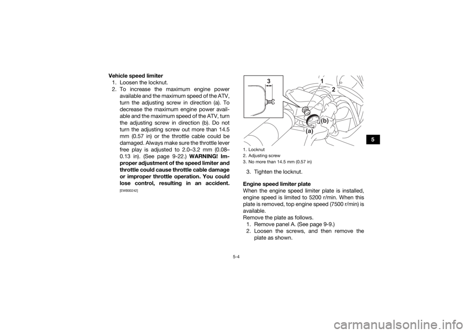
Vehicle speed limiter
1. Loosen the locknut.
2. To increase the maximum engine power available and the maximum speed of the ATV,
turn the adjusting screw in direction (a). To
decrease the maximum engine power avail-
able and the maximum speed of the ATV, turn
the adjusting screw in direction (b). Do not
turn the adjusting screw out more than 14.5
mm (0.57 in) or the throttle cable could be
damaged. Always make sure the throttle lever
free play is adjusted to 2.0–3.2 mm (0.08–
0.13 in). (See page 9-22.) WARNING! Im-
proper adjustment of the speed limiter and
throttle could cause throttle cable damage
or improper throttle operation. You could
lose control, resulting in an accident.
[EWB00242]
3. Tighten the locknut.
Engine speed limiter plate
When the engine speed limiter plate is installed,
engine speed is limited to 5200 r/min. When this
plate is removed, top engine speed (7500 r/min) is
available.
Remove the plate as follows. 1. Remove panel A. (See page 9-9.)
2. Loosen the screws, and then remove the plate as shown.1. Locknut
2. Adjusting screw
3. No more than 14.5 mm (0.57 in)
1
2
(b)
(a)
3
UBW464E0.book Page 4 Thursday, January 23, 2020 2:42 PM
Page 45 of 126
6-2
6
Throttle lever• Make sure that operation is smooth. Lubricate cable and lever
housing if necessary.
• Check lever free play, and adjust if necessary. 6-3, 9-22
Control cables • Make sure that operation is smooth. Lubricate if necessary. 9-29
Drive chain • Check chain slack, and adjust if necessary.
• Check chain condition. Lubricate if necessary. 6-3, 9-26, 9-29
Wheels and tires • Check wheel condition, and replace if damaged.
• Check tire condition and tread depth. Replace if necessary.
• Check air pressure. Correct if necessary. 6-3
Brake levers • Make sure that operation is smooth. Lubricate lever pivoting points
if necessary. 9-30
Chassis fasteners • Make sure that all nuts, bolts and screws are properly tightened. 6-6
Instruments and switches • Check operation, and correct if necessary. 6-6
ITEM ROUTINE PAGE
UBW464E0.book Page 2 Thursday, January 23, 2020 2:42 PM
Page 99 of 126
9-22
9
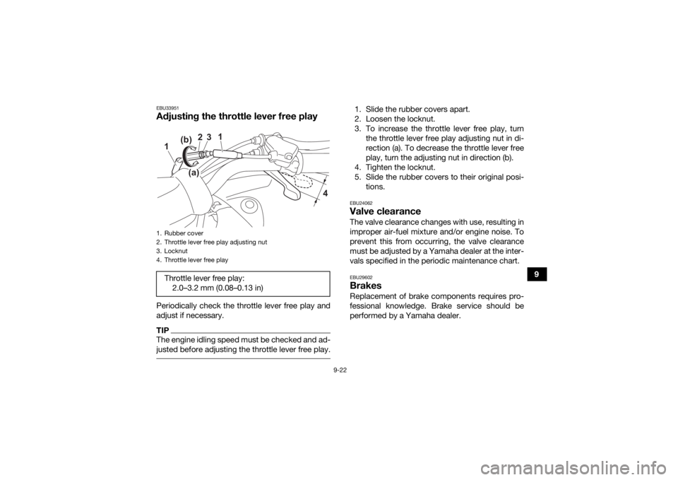
EBU33951Adjusting the throttle lever free playPeriodically check the throttle lever free play and
adjust if necessary.TIPThe engine idling speed must be checked and ad-
justed before adjusting the throttle lever free play.
1. Slide the rubber covers apart.
2. Loosen the locknut.
3. To increase the throttle lever free play, turnthe throttle lever free play adjusting nut in di-
rection (a). To decrease the throttle lever free
play, turn the adjusting nut in direction (b).
4. Tighten the locknut.
5. Slide the rubber covers to their original posi- tions.EBU24062Valve clearanceThe valve clearance changes with use, resulting in
improper air-fuel mixture and/or engine noise. To
prevent this from occurring, the valve clearance
must be adjusted by a Yamaha dealer at the inter-
vals specified in the periodic maintenance chart.EBU29602BrakesReplacement of brake components requires pro-
fessional knowledge. Brake service should be
performed by a Yamaha dealer.
1. Rubber cover
2. Throttle lever free play adjusting nut
3. Locknut
4. Throttle lever free playThrottle lever free play:2.0–3.2 mm (0.08–0.13 in)
1
2
3
1
4
(a)(b)
UBW464E0.book Page 22 Thursday, January 23, 2020 2:42 PM
Page 123 of 126
12-1
12
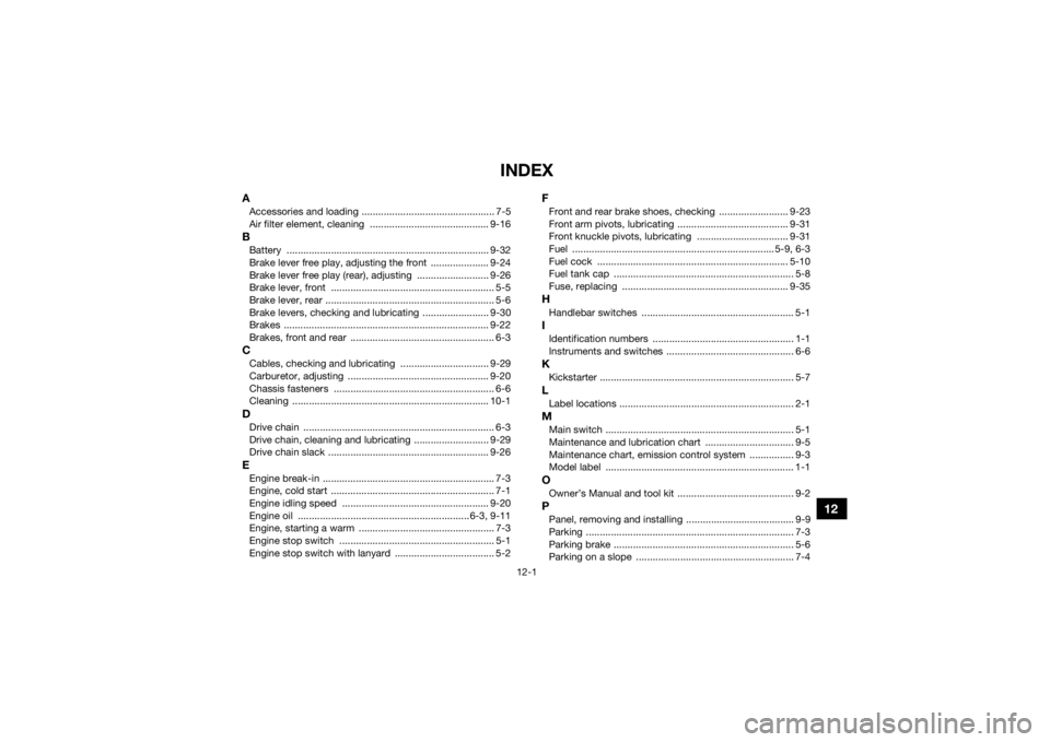
INDEX
AAccessories and loading ................................................ 7-5
Air filter element, cleaning ........................................... 9-16BBattery ......................................................................... 9-32
Brake lever free play, adjusting the front ..................... 9-24
Brake lever free play (rear), adjusting .......................... 9-26
Brake lever, front ........................................................... 5-5
Brake lever, rear ............................................................. 5-6
Brake levers, checking and lubricating ........................ 9-30
Brakes .......................................................................... 9-22
Brakes, front and rear .................................................... 6-3CCables, checking and lubricating ................................ 9-29
Carburetor, adjusting ................................................... 9-20
Chassis fasteners .......................................................... 6-6
Cleaning ....................................................................... 10-1DDrive chain ..................................................................... 6-3
Drive chain, cleaning and lubricating ........................... 9-29
Drive chain slack .......................................................... 9-26EEngine break-in .............................................................. 7-3
Engine, cold start ........................................................... 7-1
Engine idling speed ..................................................... 9-20
Engine oil ..............................................................6-3, 9-11
Engine, starting a warm ................................................. 7-3
Engine stop switch ........................................................ 5-1
Engine stop switch with lanyard .................................... 5-2
FFront and rear brake shoes, checking ......................... 9-23
Front arm pivots, lubricating ........................................ 9-31
Front knuckle pivots, lubricating ................................. 9-31
Fuel ......................................................................... 5-9, 6-3
Fuel cock ..................................................................... 5-10
Fuel tank cap ................................................................. 5-8
Fuse, replacing ............................................................ 9-35HHandlebar switches ....................................................... 5-1IIdentification numbers ................................................... 1-1
Instruments and switches .............................................. 6-6KKickstarter ...................................................................... 5-7LLabel locations ............................................................... 2-1MMain switch .................................................................... 5-1
Maintenance and lubrication chart ................................ 9-5
Maintenance chart, emission control system ................ 9-3
Model label .................................................................... 1-1OOwner’s Manual and tool kit .......................................... 9-2PPanel, removing and installing ....................................... 9-9
Parking ........................................................................... 7-3
Parking brake ................................................................. 5-6
Parking on a slope ......................................................... 7-4
UBW464E0.book Page 1 Thursday, January 23, 2020 2:42 PM
Page 124 of 126
12-2
12
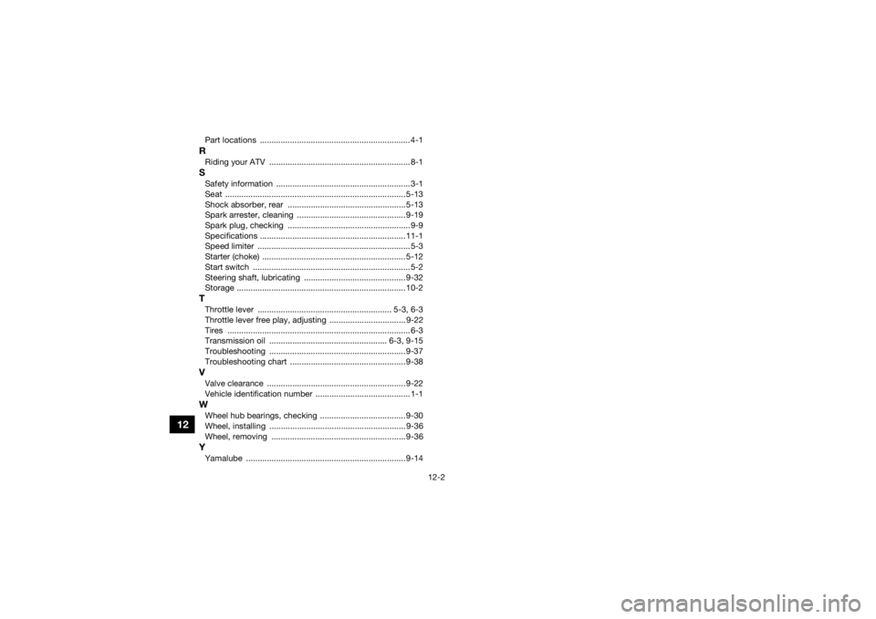
Part locations ................................................................. 4-1RRiding your ATV ............................................................. 8-1SSafety information .......................................................... 3-1
Seat .............................................................................. 5-13
Shock absorber, rear ...................................................5-13
Spark arrester, cleaning ............................................... 9-19
Spark plug, checking .....................................................9-9
Specifications ............................................................... 11-1
Speed limiter .................................................................. 5-3
Starter (choke) .............................................................. 5-12
Start switch .................................................................... 5-2
Steering shaft, lubricating ............................................ 9-32
Storage ......................................................................... 10-2TThrottle lever .......................................................... 5-3, 6-3
Throttle lever free play, adjusting ................................. 9-22
Tires ............................................................................... 6-3
Transmission oil ................................................... 6-3, 9-15
Troubleshooting ........................................................... 9-37
Troubleshooting chart .................................................. 9-38VValve clearance ............................................................ 9-22
Vehicle identification number ......................................... 1-1WWheel hub bearings, checking ..................................... 9-30
Wheel, installing ........................................................... 9-36
Wheel, removing .......................................................... 9-36YYamalube ..................................................................... 9-14UBW464E0.book Page 2 Thursday, January 23, 2020 2:42 PM