air filter YAMAHA YS125 2017 Owners Manual
[x] Cancel search | Manufacturer: YAMAHA, Model Year: 2017, Model line: YS125, Model: YAMAHA YS125 2017Pages: 90, PDF Size: 2.24 MB
Page 6 of 90

Table of contentsSafety information ............................ 1-1
Description ....................................... 2-1
Left view ......................................... 2-1
Right view ....................................... 2-2
Controls and instruments ............... 2-3
Instrument an d control functions ... 3-1
Main switch/steering lock............... 3-1
Indicator lights and warning light ............................................. 3-2
Multi-function meter unit ................ 3-3
Handlebar switches ........................ 3-5
Clutch lever .................................... 3-6
Shift pedal ...................................... 3-6
Brake lever...................................... 3-7
Brake pedal .................................... 3-7
Fuel tank cap .................................. 3-8
Fuel ................................................. 3-8
Catalytic converters ..................... 3-10
Seat .............................................. 3-11
Adjusting the shock absorber assemblies ................................ 3-11
Sidestand ..................................... 3-12
Ignition circuit cut-off system ....... 3-13 For your safety – pre-operation
checks
............................................... 4-1
Operation an d important ri din g
points ................................................. 5-1
Starting the engine .......................... 5-1
Shifting ............................................ 5-2
Tips for reducing fuel consumption ................................ 5-3
Engine break-in ............................... 5-3
Parking ............................................ 5-4
Perio dic maintenance an d
a d justment ........................................ 6-1
Owner’s tool kit ............................... 6-2
Periodic maintenance chart for the emission control system .............. 6-3
General maintenance and lubrication chart ........................... 6-4
Removing and installing the
cowling and panels ...................... 6-8
Checking the spark plug ............... 6-10
Engine oil and oil filter element ..... 6-11
Cleaning the air filter element and cleaning the check hose ............ 6-14
Adjusting the engine idling
speed ......................................... 6-16
Checking the throttle grip free play ............................................ 6-16
Valve clearance ............................. 6-17
Tires .............................................. 6-17 Cast wheels .................................. 6-19
Adjusting the clutch lever free
play ............................................ 6-19
Checking the brake lever free play ............................................ 6-20
Adjusting the brake pedal free play ............................................ 6-21
Brake light switches ..................... 6-21
Checking the front brake pads
and rear brake shoes ............... 6-22
Checking the brake fluid level ...... 6-22
Changing the brake fluid ............. 6-23
Drive chain slack........................... 6-24
Cleaning and lubricating the
drive chain ................................. 6-25
Checking and lubricating the cables ........................................ 6-26
Checking and lubricating the throttle grip and cable ............... 6-26
Checking and lubricating the
brake and shift pedals............... 6-26
Checking and lubricating the brake and clutch levers ............. 6-27
Checking and lubricating the centerstand and sidestand........ 6-28
Lubricating the swingarm
pivots......................................... 6-28
Checking the front fork ................. 6-29
Checking the steering................... 6-29
Checking the wheel bearings ....... 6-30
Battery .......................................... 6-30UBT4E0E0.book Page 1 Thursday, November 17, 2016 10:55 AM
Page 13 of 90
Description
2-1
2
EAU10411
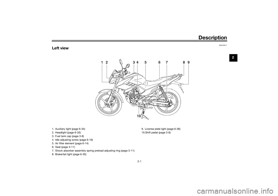
Left view
4
7
1
2
8
9
3
6
5
10
1. Auxiliary light (page 6-34)
2. Headlight (page 6-33)
3. Fuel tank cap (page 3-8)
4. Idle adjusting screw (page 6-16)
5. Air filter element (page 6-14)
6. Seat (page 3-11)
7. Shock absorber assembly spring preload adjusting ring (page 3-11)
8. Brake/tail light (page 6-35) 9. License plate light (page 6-36)
10.Shift pedal (page 3-6)
UBT4E0E0.book Page 1 Thursday, November 17, 2016 10:55 AM
Page 39 of 90

Periodic maintenance an d a djustment
6-4
6
EAU71342
General maintenance an d lu brication chartNO. ITEM CHECK OR MAINTENANCE JOB ODOMETER READING
ANNUAL
CHECK
1000 km
(600 mi) 6000 km
(3500 mi) 12000 km
(7000 mi) 18000 km
(10500 mi) 24000 km
(14000 mi)
1 *Dia
gnostic system
check • Perform dynamic inspection us-
ing Yamaha diagnostic tool.
• Check the error codes. √√√√√√
2 *Air filter element • Clean.
√√
•Replace. √√
3 Air filter case check
hose
• Clean.
√√√√√
4Clutch • Check operation.
•Adjust.
√√√√√
5 *Front brake • Check operation, fluid level, and
for fluid leakage.
• Replace brake pads if necessary. √√√√√√
6 *Rear brake • Check operation.
• Adjust brake pedal free play.
• Replace brake shoes if neces-
sary. √√√√√√
7 *Brake hose • Check for cracks or damage.
√√√√√
• Replace. Every 4 years
8 *Brake flui d • Change. Every 2 years
9 *Wheels • Check runout and for damage.
• Replace if necessary.
√√√√
UBT4E0E0.book Page 4 Thursday, November 17, 2016 10:55 AM
Page 42 of 90
Periodic maintenance an d a djustment
6-7
6
EAU72690
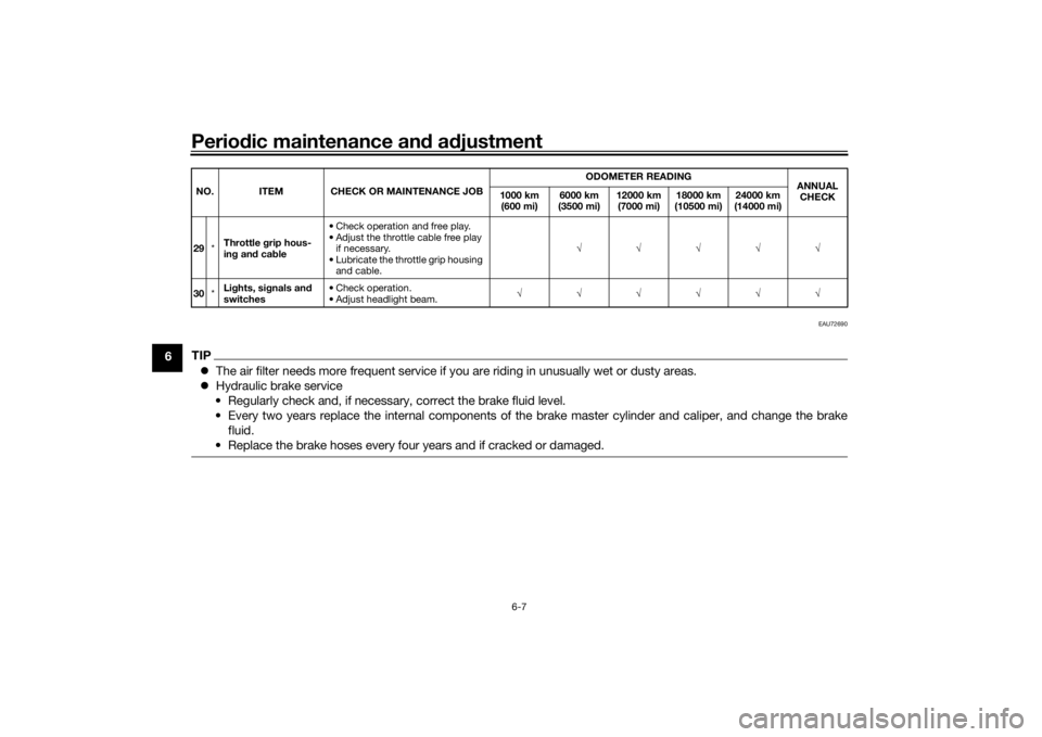
TIP The air filter needs more frequent service if you are riding in unusually wet or dusty areas.
Hydraulic brake service
• Regularly check and, if necessary, correct the brake fluid level.
• Every two years replace the internal components of the brake master cylinder and caliper, and change the brake fluid.
• Replace the brake hoses every four years and if cracked or damaged.29 *Throttle
grip hous-
in g an d cab le • Check operation and free play.
• Adjust the throttle cable free play
if necessary.
• Lubricate the throttle grip housing and cable. √√√√√
30 *Li
ghts, si gnals an d
switches • Check operation.
• Adjust headlight beam.
√√√√√√
NO. ITEM CHECK OR MAINTENANCE JOB
ODOMETER READING
ANNUAL
CHECK
1000 km
(600 mi) 6000 km
(3500 mi) 12000 km
(7000 mi) 18000 km
(10500 mi) 24000 km
(14000 mi)UBT4E0E0.book Page 7 Thursday, November 17, 2016 10:55 AM
Page 46 of 90
Periodic maintenance an d a djustment
6-11
6
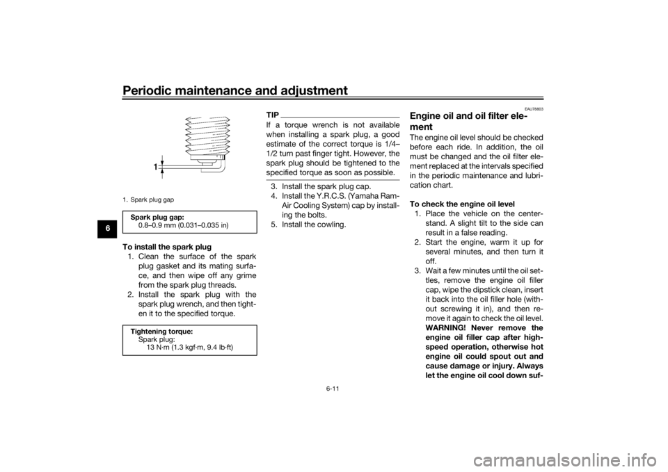
To install the spark plu g
1. Clean the surface of the spark plug gasket and its mating surfa-
ce, and then wipe off any grime
from the spark plug threads.
2. Install the spark plug with the spark plug wrench, and then tight-
en it to the specified torque.
TIPIf a torque wrench is not available
when installing a spark plug, a good
estimate of the correct torque is 1/4–
1/2 turn past finger tight. However, the
spark plug should be tightened to the
specified torque as soon as possible.3. Install the spark plug cap.
4. Install the Y.R.C.S. (Yamaha Ram-Air Cooling System) cap by install-
ing the bolts.
5. Install the cowling.
EAU78803
En gine oil an d oil filter ele-
mentThe engine oil level should be checked
before each ride. In addition, the oil
must be changed and the oil filter ele-
ment replaced at the intervals specified
in the periodic maintenance and lubri-
cation chart.
To check the en gine oil level
1. Place the vehicle on the center- stand. A slight tilt to the side can
result in a false reading.
2. Start the engine, warm it up for several minutes, and then turn it
off.
3. Wait a few minutes until the oil set- tles, remove the engine oil filler
cap, wipe the dipstick clean, insert
it back into the oil filler hole (with-
out screwing it in), and then re-
move it again to check the oil level.
WARNING! Never remove the
engine oil filler cap after hi gh-
speed operation, otherwise hot
en gine oil coul d spout out an d
cause damag e or injury. Always
let the en gine oil cool down suf-
1. Spark plug gapSpark plu g g ap:
0.8–0.9 mm (0.031–0.035 in)
Ti ghtenin g torque:
Spark plug: 13 N·m (1.3 kgf·m, 9.4 lb·ft)
UBT4E0E0.book Page 11 Thursday, November 17, 2016 10:55 AM
Page 48 of 90
Periodic maintenance an d a djustment
6-13
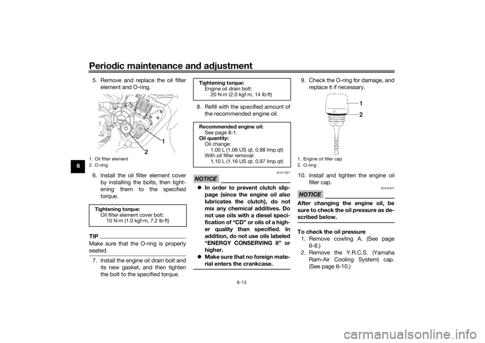
6 5. Remove and replace the oil filter
element and O-ring.
6. Install the oil filter element cover by installing the bolts, then tight-
ening them to the specified
torque.
TIPMake sure that the O-ring is properly
seated.7. Install the engine oil drain bolt andits new gasket, and then tighten
the bolt to the specified torque. 8. Refill with the specified amount of
the recommended engine oil.
NOTICE
ECA11621
In or der to prevent clutch slip-
pa ge (since the en gine oil also
lu bricates the clutch), do not
mix any chemical additives. Do
not use oils with a diesel speci-
fication of “CD” or oils of a hi gh-
er quality than specifie d. In
a ddition, do not use oils la beled
“ENERGY CONSERVING II” or
hi gher.
Make sure that no forei gn mate-
rial enters the crankcase.
9. Check the O-ring for damage, and replace it if necessary.
10. Install and tighten the engine oil filler cap.NOTICE
ECA10441
After chan gin g the en gine oil, b e
sure to check the oil pressure as de-
scri bed b elow.To check the oil pressure
1. Remove cowling A. (See page 6-8.)
2. Remove the Y.R.C.S. (Yamaha Ram-Air Cooling System) cap.
(See page 6-10.)
1. Oil filter element
2. O-ringTightenin g torque:
Oil filter element cover bolt: 10 N·m (1.0 kgf·m, 7.2 lb·ft)
2 1
Ti
ghtenin g torque:
Engine oil drain bolt:
20 N·m (2.0 kgf·m, 14 lb·ft)
Recommen ded en gine oil:
See page 8-1.
Oil quantity:
Oil change:1.00 L (1.06 US qt, 0.88 Imp.qt)
With oil filter removal:
1.10 L (1.16 US qt, 0.97 Imp.qt)
1. Engine oil filler cap
2. O-ring
21
UBT4E0E0.book Page 13 Thursday, November 17, 2016 10:55 AM
Page 49 of 90
Periodic maintenance an d a djustment
6-14
6
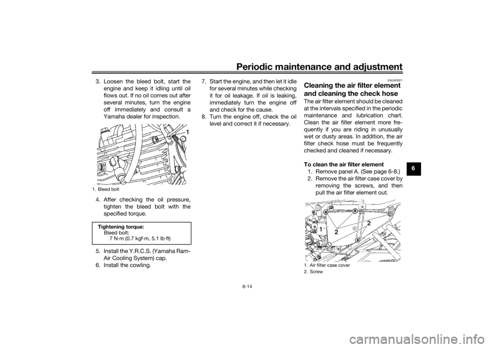
3. Loosen the bleed bolt, start the
engine and keep it idling until oil
flows out. If no oil comes out after
several minutes, turn the engine
off immediately and consult a
Yamaha dealer for inspection.
4. After checking the oil pressure, tighten the bleed bolt with the
specified torque.
5. Install the Y.R.C.S. (Yamaha Ram- Air Cooling System) cap.
6. Install the cowling. 7. Start the engine, and then let it idle
for several minutes while checking
it for oil leakage. If oil is leaking,
immediately turn the engine off
and check for the cause.
8. Turn the engine off, check the oil level and correct it if necessary.
EAUW3321
Cleanin g the air filter element
an d cleanin g the check hoseThe air filter element should be cleaned
at the intervals specified in the periodic
maintenance and lubrication chart.
Clean the air filter element more fre-
quently if you are riding in unusually
wet or dusty areas. In addition, the air
filter check hose must be frequently
checked and cleaned if necessary.
To clean the air filter element
1. Remove panel A. (See page 6-8.)
2. Remove the air filter case cover by removing the screws, and then
pull the air filter element out.
1. Bleed boltTightenin g torque:
Bleed bolt: 7 N·m (0.7 kgf·m, 5.1 lb·ft)
1
1. Air filter case cover
2. Screw
2 2
1
UBT4E0E0.book Page 14 Thursday, November 17, 2016 10:55 AM
Page 50 of 90
Periodic maintenance an d a djustment
6-15
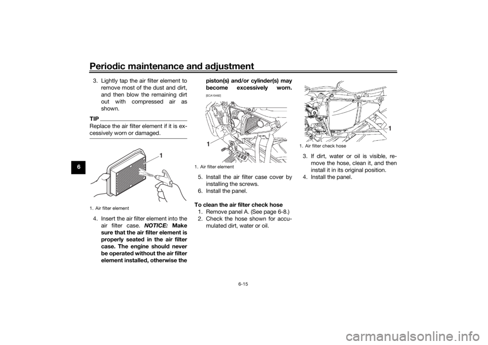
6 3. Lightly tap the air filter element to
remove most of the dust and dirt,
and then blow the remaining dirt
out with compressed air as
shown.
TIPReplace the air filter element if it is ex-
cessively worn or damaged.4. Insert the air filter element into theair filter case. NOTICE: Make
sure that the air filter element is
properly seate d in the air filter
case. The en gine shoul d never
b e operated without the air filter
element installe d, otherwise the piston(s) an
d/or cylin der(s) may
b ecome excessively worn.
[ECA10482]
5. Install the air filter case cover by
installing the screws.
6. Install the panel.
To clean the air filter check hose 1. Remove panel A. (See page 6-8.)
2. Check the hose shown for accu- mulated dirt, water or oil. 3. If dirt, water or oil is visible, re-
move the hose, clean it, and then
install it in its original position.
4. Install the panel.
1. Air filter element
1
1. Air filter element
1
1. Air filter check hose
1
UBT4E0E0.book Page 15 Thursday, November 17, 2016 10:55 AM
Page 81 of 90
Specifications
8-1
8
Dimensions:Overall length:2005 mm (78.9 in)
Overall width:
735 mm (28.9 in)
Overall height: 1050 mm (41.3 in)
Seat height: 795 mm (31.3 in)
Wheelbase:
1320 mm (52.0 in)
Ground clearance: 150 mm (5.91 in)
Minimum turning radius: 2.2 m (7.22 ft)Wei ght:Curb weight:
129 kg (284 lb)Engine:Combustion cycle:
4-stroke
Cooling system: Air cooled
Valve train: SOHC
Number of cylinders:
Single cylinder
Displacement: 125 cm³
Bore × stroke:
52.4 × 57.9 mm (2.06 × 2.28 in)
Compression ratio:
10.0 : 1 Starting system:
Electric starter
Lubrication system: Wet sump
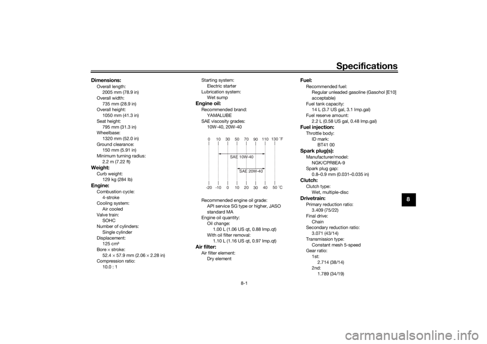
Engine oil:Recommended brand:
YAMALUBE
SAE viscosity grades: 10W-40, 20W-40
Recommended engine oil grade: API service SG type or higher, JASO
standard MA
Engine oil quantity:
Oil change:1.00 L (1.06 US qt, 0.88 Imp.qt)
With oil filter removal:
1.10 L (1.16 US qt, 0.97 Imp.qt)Air filter:Air filter element:Dry element
Fuel:Recommended fuel:Regular unleaded gasoline (Gasohol [E10]
acceptable)
Fuel tank capacity: 14 L (3.7 US gal, 3.1 Imp.gal)
Fuel reserve amount:
2.2 L (0.58 US gal, 0.48 Imp.gal)Fuel injection:Throttle body:ID mark:BT41 00Spark plu g(s):Manufacturer/model:
NGK/CPR8EA-9
Spark plug gap: 0.8–0.9 mm (0.031–0.035 in)Clutch:Clutch type:
Wet, multiple-discDrivetrain:Primary reduction ratio:3.409 (75/22)
Final drive:
Chain
Secondary reduction ratio: 3.071 (43/14)
Transmission type: Constant mesh 5-speed
Gear ratio:
1st:2.714 (38/14)
2nd:
1.789 (34/19)
010305070 90110
130 ˚F
-20 -10 0 10 20 3040
50 ˚C
SAE 10W-40
SAE 20W-40
UBT4E0E0.book Page 1 Thursday, November 17, 2016 10:55 AM
Page 86 of 90

10-1
10
IndexAAir filter element and check hose,
cleaning .............................................. 6-14
Auxiliary light bulb, replacing ................ 6-34BBattery .................................................. 6-30
Brake and clutch levers, checking and lubricating ........................................... 6-27
Brake and shift pedals, checking and
lubricating ........................................... 6-26
Brake fluid, changing ............................ 6-23
Brake fluid level, checking .................... 6-22
Brake lever .............................................. 3-7
Brake lever free play, checking............. 6-20
Brake light switches.............................. 6-21
Brake pads and shoes, checking ......... 6-22
Brake pedal............................................. 3-7
Brake pedal free play, adjusting ........... 6-21
Brake/tail light bulb, replacing .............. 6-35CCables, checking and lubricating ......... 6-26
Care ........................................................ 7-1
Catalytic converters .............................. 3-10
Centerstand and sidestand, checking and lubricating .................................... 6-28
Clutch lever ............................................. 3-6
Clutch lever free play, adjusting ........... 6-19
Cowling and panels, removing and installing................................................ 6-8DData recording, vehicle ........................... 9-2
Diagnostic connector.............................. 9-2
Dimmer switch ........................................ 3-5
Drive chain, cleaning and lubricating .... 6-25 Drive chain slack .................................. 6-24
EEco indicator light................................... 3-2
Engine break-in ...................................... 5-3
Engine idling speed .............................. 6-16
Engine oil and oil filter element ............ 6-11
Engine serial number .............................. 9-1
Engine trouble warning light ................... 3-2FFront fork, checking ............................. 6-29
Fuel ......................................................... 3-8
Fuel consumption, tips for reducing ...... 5-3
Fuel tank cap .......................................... 3-8
Fuse, replacing ..................................... 6-31HHandlebar switches ................................ 3-5
Headlight bulb, replacing ..................... 6-33
High beam indicator light ....................... 3-2
Horn switch ............................................ 3-5IIdentification numbers ............................ 9-1
Ignition circuit cut-off system ............... 3-13
Indicator lights and warning light ........... 3-2LLicense plate light bulb, replacing........ 6-36MMain switch/steering lock....................... 3-1
Maintenance and lubrication, periodic ... 6-4
Maintenance, emission control
system.................................................. 6-3
Matte color, caution ............................... 7-1
Model label ............................................. 9-1
Multi-function meter unit ........................ 3-3
NNeutral indicator light ..............................3-2PParking ....................................................5-4
Part locations ..........................................2-1
Pass switch .............................................3-5SSafety information ...................................1-1
Seat .......................................................3-11
Shifting ....................................................5-2
Shift pedal ...............................................3-6
Shock absorber assemblies, adjusting .............................................3-11
Sidestand ..............................................3-12
Spark plug, checking ............................6-10
Specifications .........................................8-1
Starting the engine ..................................5-1
Start switch .............................................3-6
Steering, checking ................................6-29
Storage ...................................................7-3
Swingarm pivots, lubricating ................6-28TThrottle grip and cable, checking and lubricating ...........................................6-26
Throttle grip free play, checking ...........6-16
Tires ......................................................6-17
Tool kit ....................................................6-2
Troubleshooting ....................................6-39
Troubleshooting chart ...........................6-41
Turn signal indicator light........................3-2
Turn signal light bulb, replacing ............6-35
Turn signal switch ...................................3-5VValve clearance .....................................6-17
UBT4E0E0.book Page 1 Thursday, November 17, 2016 10:55 AM