instrument panel YAMAHA YS125 2017 Owners Manual
[x] Cancel search | Manufacturer: YAMAHA, Model Year: 2017, Model line: YS125, Model: YAMAHA YS125 2017Pages: 90, PDF Size: 2.24 MB
Page 6 of 90

Table of contentsSafety information ............................ 1-1
Description ....................................... 2-1
Left view ......................................... 2-1
Right view ....................................... 2-2
Controls and instruments ............... 2-3
Instrument an d control functions ... 3-1
Main switch/steering lock............... 3-1
Indicator lights and warning light ............................................. 3-2
Multi-function meter unit ................ 3-3
Handlebar switches ........................ 3-5
Clutch lever .................................... 3-6
Shift pedal ...................................... 3-6
Brake lever...................................... 3-7
Brake pedal .................................... 3-7
Fuel tank cap .................................. 3-8
Fuel ................................................. 3-8
Catalytic converters ..................... 3-10
Seat .............................................. 3-11
Adjusting the shock absorber assemblies ................................ 3-11
Sidestand ..................................... 3-12
Ignition circuit cut-off system ....... 3-13 For your safety – pre-operation
checks
............................................... 4-1
Operation an d important ri din g
points ................................................. 5-1
Starting the engine .......................... 5-1
Shifting ............................................ 5-2
Tips for reducing fuel consumption ................................ 5-3
Engine break-in ............................... 5-3
Parking ............................................ 5-4
Perio dic maintenance an d
a d justment ........................................ 6-1
Owner’s tool kit ............................... 6-2
Periodic maintenance chart for the emission control system .............. 6-3
General maintenance and lubrication chart ........................... 6-4
Removing and installing the
cowling and panels ...................... 6-8
Checking the spark plug ............... 6-10
Engine oil and oil filter element ..... 6-11
Cleaning the air filter element and cleaning the check hose ............ 6-14
Adjusting the engine idling
speed ......................................... 6-16
Checking the throttle grip free play ............................................ 6-16
Valve clearance ............................. 6-17
Tires .............................................. 6-17 Cast wheels .................................. 6-19
Adjusting the clutch lever free
play ............................................ 6-19
Checking the brake lever free play ............................................ 6-20
Adjusting the brake pedal free play ............................................ 6-21
Brake light switches ..................... 6-21
Checking the front brake pads
and rear brake shoes ............... 6-22
Checking the brake fluid level ...... 6-22
Changing the brake fluid ............. 6-23
Drive chain slack........................... 6-24
Cleaning and lubricating the
drive chain ................................. 6-25
Checking and lubricating the cables ........................................ 6-26
Checking and lubricating the throttle grip and cable ............... 6-26
Checking and lubricating the
brake and shift pedals............... 6-26
Checking and lubricating the brake and clutch levers ............. 6-27
Checking and lubricating the centerstand and sidestand........ 6-28
Lubricating the swingarm
pivots......................................... 6-28
Checking the front fork ................. 6-29
Checking the steering................... 6-29
Checking the wheel bearings ....... 6-30
Battery .......................................... 6-30UBT4E0E0.book Page 1 Thursday, November 17, 2016 10:55 AM
Page 26 of 90

Instrument and control functions
3-11
3
EAU78851
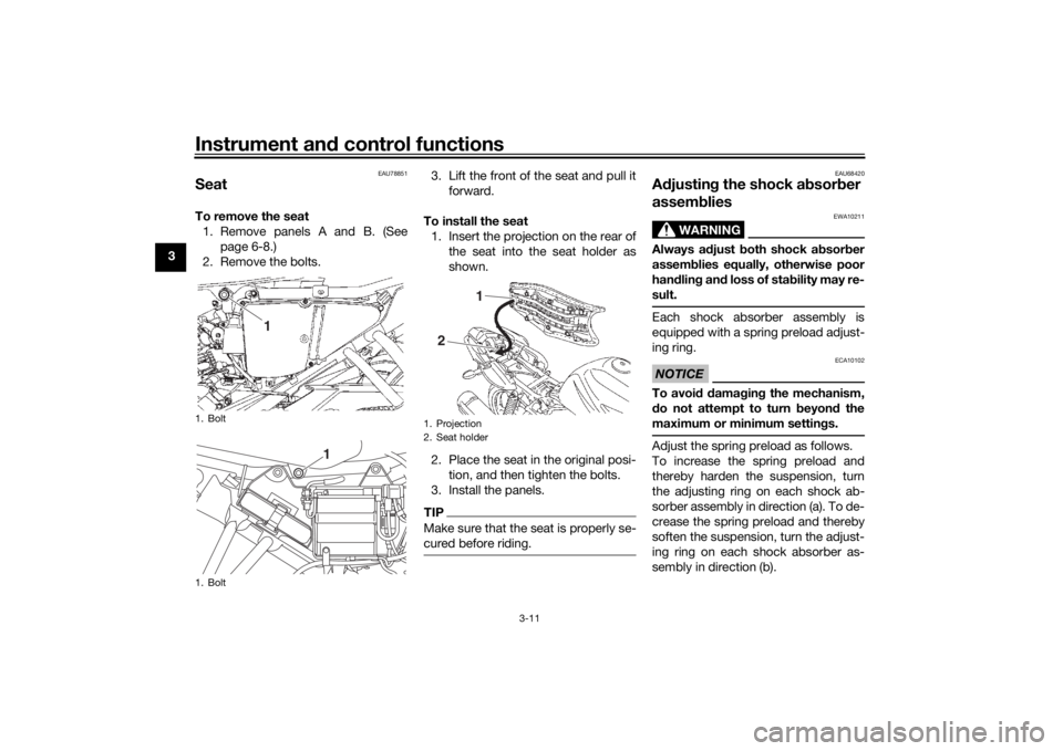
SeatTo remove the seat
1. Remove panels A and B. (See page 6-8.)
2. Remove the bolts. 3. Lift the front of the seat and pull it
forward.
To install the seat 1. Insert the projection on the rear of the seat into the seat holder as
shown.
2. Place the seat in the original posi- tion, and then tighten the bolts.
3. Install the panels.
TIPMake sure that the seat is properly se-
cured before riding.
EAU68420
A djustin g the shock a bsorb er
assem blies
WARNING
EWA10211
Always a djust both shock a bsor ber
assem blies equally, otherwise poor
han dlin g an d loss of sta bility may re-
sult.Each shock absorber assembly is
equipped with a spring preload adjust-
ing ring.NOTICE
ECA10102
To avoi d d amag ing the mechanism,
d o not attempt to turn b eyond the
maximum or minimum settin gs.Adjust the spring preload as follows.
To increase the spring preload and
thereby harden the suspension, turn
the adjusting ring on each shock ab-
sorber assembly in direction (a). To de-
crease the spring preload and thereby
soften the suspension, turn the adjust-
ing ring on each shock absorber as-
sembly in direction (b).
1. Bolt
1. Bolt
1
1
1. Projection
2. Seat holder
1
2
UBT4E0E0.book Page 11 Thursday, November 17, 2016 10:55 AM