coolant temperature YAMAHA YXZ1000R 2021 Owners Manual
[x] Cancel search | Manufacturer: YAMAHA, Model Year: 2021, Model line: YXZ1000R, Model: YAMAHA YXZ1000R 2021Pages: 200, PDF Size: 4.96 MB
Page 33 of 200

5-2
5
EBU31269Indicator lights and warning lights
EBU35450Neutral indicator light “N”
This indicator light comes on when the trans-
mission is in the neutral position.EBU35460Reverse indicator light “R”
This indicator light co mes on when the trans-
mission is in the reverse position.
1. Shift light
2. Electric Power Steering warning light “EPS”
3. Differential gear lock in dicator light “DIFF. LOCK”
4. Parking brake indicator light “(P)”
5. Reverse indicator light “R”
6. Neutral indicator light “N”
7. Engine trouble warning light “ ”
8. High beam indicator light “ ”
9. Coolant temperature warning light “ ”
10.Drivetrain icon “ / ”
1
2
3
45
6
78
10
9
1. Helmet reminder light ç é
2. Seat belt reminder light ç é
12
UB5J7CE0.book Page 2 Thursday, November 26, 2020 1:37 PM
Page 35 of 200

5-4
5
and/or turn the steering wheel back and
forth to help the differential to lock or un-
lock. EBU34932Shift light
This light can be set to come on and go off at
the desired engine speeds and is used to in-
form the driver when it is time to upshift.
The electrical circuit of the shift light can be
checked by turning the key to “ ” (on). If the
light does not come on initially when the key
is turned to “ ” (on), or if the light remains
on, have a Yamaha dealer check the electrical
circuit.TIPSee page 5-13 for an explanation of how to
set the shift light.
EBU35283Coolant temperature warning light “ ”
This warning light comes on when the coolant
temperature, and therefore the engine, is out-
side its normal operating temperature range.
The warning light comes on in blue to inform
the driver that the vehicle should be warmed
up. After the engine is started, warm it up until
the warning light goes off.
The vehicle can be operated normally when
the warning light is off.
The warning light comes on in red when the
engine is overheating. If the red light comes
on, stop the vehicle as soon as it is safe to do
so and allow the engine to idle for about 10
minutes. If the warning light does not go off,
stop the engine and allow it to cool. (See page
9-69.)TIPIf you continue to driv e the vehicle while the
engine is overheating, a buzzer will sound.
UB5J7CE0.book Page 4 Thursday, November 26, 2020 1:37 PM
Page 36 of 200

5-5
5
The coolant temperature warning light can
be checked by turning the key to “ ” (on).
The warning light should come on in purple
briefly (which confirms that both the blue
and red indicators are okay) and then go
off. If the warning light does not come on at
all, comes on in red or blue, or if the warning
light remains on, have a Yamaha dealer
check the vehicle. NOTICEECB02040The engine may overheat if the vehicle is
overloaded. If this happens, reduce the
load to specification.
After restarting, make sure that the
warning light is out. Continuous use
while this warning light is on may cause
damage to the engine.
EBU31342Engine trouble warning light “ ”
This warning light comes on or flashes if a
problem is detected in the electrical circuit
monitoring the engine. When this occurs, the
display will indicate an error code (see page
5-15). Have a Yamaha dealer check the self-
diagnostic system.
The electrical circuit of the warning light can
be checked by turning the key to “ ” (on). If
the warning light does not come on initially
when the key is turned to “ ” (on), or if the
warning light remains on, have a Yamaha
dealer check the vehicle.EBU33041Electric Power Steering warning light
“EPS”
This warning light comes on when the key is
turned to “ ” (on), and then goes off once
the engine is started. If the warning light re-
mains on or comes on after the engine is
UB5J7CE0.book Page 5 Thursday, November 26, 2020 1:37 PM
Page 38 of 200

5-7
5
EBU3495DMulti-function meter unitThe multi-function meter unit is equipped with
the following:
speedometer
tachometer
odometer
two tripmeters
clock
hour meter
voltage display
coolant temperature display
fuel gauge
transmission gear display
shift light control mode
error code display1. Tachometer
2. Transmission gear display
3. Shift light
4. Speedometer
5. “SELECT” button
6. “MODE” button
7. “RESET” button
8. Clock/Hour meter/Voltage display/Coolant temperature
display
9. Fuel gauge
10.Odometer/Tripmeter A/Tripmeter B
123456
10 9 8 7
UB5J7CE0.book Page 7 Thursday, November 26, 2020 1:37 PM
Page 41 of 200

5-10
5
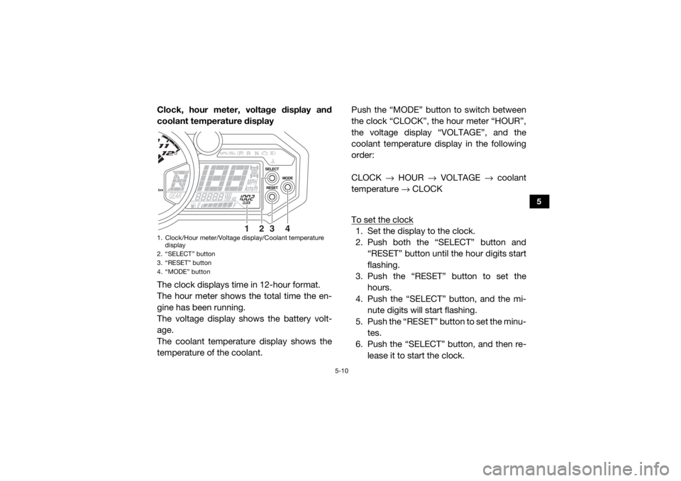
Clock, hour meter, voltage display and
coolant temperature display
The clock displays time in 12-hour format.
The hour meter shows the total time the en-
gine has been running.
The voltage display shows the battery volt-
age.
The coolant temperature display shows the
temperature of the coolant.Push the “MODE” button to switch between
the clock “CLOCK”, the hour meter “HOUR”,
the voltage display “VOLTAGE”, and the
coolant temperature display in the following
order:
CLOCK
→ HOUR → VOLTAGE → coolant
temperature → CLOCK
To set the clock
1. Set the display to the clock.
2. Push both the “SELECT” button and “RESET” button until th e hour digits start
flashing.
3. Push the “RESET” button to set the
hours.
4. Push the “SELECT” button, and the mi- nute digits will start flashing.
5. Push the “RESET” button to set the minu- tes.
6. Push the “SELECT” button, and then re-
lease it to start the clock.
1. Clock/Hour meter/Voltage display/Coolant temperature display
2. “SELECT” button
3. “RESET” button
4. “MODE” button
23
4
1
UB5J7CE0.book Page 10 Thursday, November 26, 2020 1:37 PM
Page 42 of 200

5-11
5
Voltage displayThis display shows “ ” and the battery volt-
age.
When the battery voltage is low, “LO” will be
displayed. When the battery voltage is high,
“HI” will be displayed.
NOTICEECB02050If the voltage display indicates “LO” or
“HI”, there may be trouble with the battery
charging circuit or the battery may be
faulty. If this occurs, have a Yamaha dealer
check or repair the vehicle. Coolant temperature displayWhen the coolant temperature is in the nor-
mal operating range, the temperature will be
displayed. When the coolant temperature is
1. Voltage display
1
1. Coolant temperature display
1
UB5J7CE0.book Page 11 Thursday, November 26, 2020 1:37 PM
Page 43 of 200

5-12
5
low, “LO” will be displayed. When the coolant
temperature rises, the coolant temperature
display will begin to flash. If the coolant tem-
perature continues to rise, the message “HI”
will flash.TIPThe coolant temperature display can be set
to “°C” or “°F”. To switch the temperature
units, turn the key to “ ” (off), then hold
the “RESET” button pushed and turn the
key to “ ” (on).
The radiator fans turn on and off automati-
cally according to the coolant temperature.
Fuel gauge
The fuel gauge indicates the amount of fuel in
the fuel tank. The display segments of the fuel
gauge disappear from “F” (full) towards “E”
(empty) as the fuel level decreases. When the
last segment on the left flashes, refuel as
soon as possible.1. Fuel gauge
1
UB5J7CE0.book Page 12 Thursday, November 26, 2020 1:37 PM
Page 87 of 200

7-2
7
10–20 hours:
Avoid prolonged operation above 6300 r/min.
After break-in:
The vehicle may now be operated normally.EBU35342Starting the engine1. Turn the key to “ ” (on).NOTICEECB02291The coolant temperature warning light and
engine trouble warning light should come
on, then go off.
The EPS warning light should come on,
then go off when the engine is started.
To avoid possible damage, do not operate
the vehicle if a warning light does not work
as described above. 2. Press the brake pedal.
3. Shift the transmission into neutral.
When the transmission is in the neutral
position, the transmission gear display
shows “N” and the neutral indicator
light should come on.
The engine can be started in any gear if
the clutch pedal is applied. However, it
is recommended to shift into neutral
before starting the engine.
4. With your foot off the accelerator pedal, start the engine by turning the key to “ ”
(start).
If the engine fails to start, release the key, and
then try starting it again. Wait a few seconds
before the next attempt. Each attempt should
be as short as possible, to preserve battery
energy. NOTICE: Do not crank the engine
more than 5 seconds on each attempt, or
starter damage could occur. Wait at least
5 seconds between each operation of the
electric starter to let it cool.
[ECB02140]
Do not turn the key to the “ ” (start) position
with the engine running; otherwise, damage
to the electric starter may result.
UB5J7CE0.book Page 2 Thursday, November 26, 2020 1:37 PM
Page 194 of 200

11-5
11
Rear suspension:Type:Double wishbone
Spring:
Coil spring
Shock absorber: Gas-hydraulic damper
Wheel travel: 432 mm (17.0 in)Electrical system:System voltage:12 V
Ignition system: TCI
Charging system:
AC magnetoBattery:Model:U1-H11L
Voltage, capacity:
12 V, 28.0 AhLights:Headlight:LED
Brake/tail light:
LED
Meter lighting: LED
Neutral indicator light: LED High beam indicator light:
LED
Reverse indicator light: LED
Coolant temperature warning light:
LED
Parking brake indicator light: LED
Engine trouble warning light: LED
Differential gear lock indicator light:
LED
EPS warning light: LED
Helmet reminder light: 0.8 W
Seat belt reminder light:
0.8 W
Shift timing indicator light: LED
Fuses:Main fuse:
50.0 A
Fuel injection system fuse: 15.0 A
EPS fuse: 40.0 A
Headlight fuse:
15.0 A
Signaling system fuse: 10.0 A
UB5J7CE0.book Page 5 Thursday, November 26, 2020 1:37 PM
Page 197 of 200

13-1
13
INDEX
AAccelerator pedal ......................................................... 5-18
Accelerator pedal, checking ........................................ 9-50
Accelerator pedal, Pre-operation check ........................ 6-7
Air filter ......................................................................... 9-39
Air filter case hoses, cleaning ...................................... 9-43
Auxiliary DC jack .......................................................... 5-43
Axle boots .................................................................... 9-36BBasic guide for safe use ................................................ 8-1
Battery, Periodic maintenance .................................... 9-58
Brake and clutch fluid levels, checking ....................... 9-47
Brake fluid, replacing ................................................... 9-49
Brake light switch, adjusting ........................................ 9-52
Brake pedal .................................................................. 5-19
Brake pedal, checking ................................................. 9-49
Brakes, Periodic maintenance ..................................... 9-45
Brakes, Pre-operation check ......................................... 6-3
Brake/tail light .............................................................. 9-66CCable, inspecting and lubrication ................................ 9-52
Cargo bed .................................................................... 5-27
Cleaning ....................................................................... 10-1
Clutch pedal ................................................................. 5-18
Clutch pedal, checking ................................................ 9-49
Clutch, Pre-operation check .......................................... 6-3
Control cables, Pre-operation check ............................. 6-8
Coolant, Periodic maintenance ................................... 9-34
Coolant, Pre-operation check ........................................ 6-6Coolant temperature warning light ................................ 5-4
Cup holders ................................................................. 5-26
DData recording, vehicle ................................................ 12-1
Differential gear lock indicator light ............................... 5-3
Differential gear oil, Periodic maintenance .................. 9-32
Differential gear, Pre-operation check ........................... 6-6
Doors ........................................................................... 5-21
Drive mode, selecting .................................................... 7-7
Driver seat position ...................................................... 5-23
Drive shaft universal joint, lubrication .......................... 9-55
Drivetrain icon ................................................................ 5-3EEngine break-in .............................................................. 7-1
Engine oil and oil filter, Periodic maintenance ............. 9-16
Engine oil, Pre-operation check .................................... 6-6
Engine trouble warning light .......................................... 5-5
EPS warning light .......................................................... 5-5FFinal gear oil, Periodic maintenance ............................ 9-30
Final gear, Pre-operation check .................................... 6-6
Fittings and fasteners, Pre-operation check ................. 6-8
Flag pole bracket ......................................................... 5-28
Four–wheel drive knob (On–Command 4WD) ............. 5-17
Front and rear brake pads, checking .......................... 9-46
Fuel, Pre-operation check ............................................. 6-4
Fuel tank cap ............................................................... 5-21
Fuse, replacing ............................................................ 9-63GGlove compartment ..................................................... 5-25
UB5J7CE0.book Page 1 Thursday, November 26, 2020 1:37 PM