check engine light YAMAHA YXZ1000R SS 2017 Owners Manual
[x] Cancel search | Manufacturer: YAMAHA, Model Year: 2017, Model line: YXZ1000R SS, Model: YAMAHA YXZ1000R SS 2017Pages: 208, PDF Size: 4.79 MB
Page 7 of 208

FOR YOUR SAFETY –
PRE-OPERATION CHECKS .................... 5-1Front and rear brakes ........................... 5-3
Clutch ................................................... 5-3
Fuel ....................................................... 5-4
Engine oil .............................................. 5-5
Transmission ........................................ 5-6
Coolant ................................................. 5-6
Final gear .............................................. 5-6
Differential gear .................................... 5-7
Accelerator pedal ................................. 5-7
Seat belts ............................................. 5-7
Passenger handhold ............................ 5-7
Steering ................................................ 5-7
Shift lever.............................................. 5-8
Fittings and fasteners ........................... 5-8
Instruments, lights and switches .......... 5-8
Control cables ...................................... 5-8
Tires ...................................................... 5-8
OPERATION ............................................ 6-1 Engine break-in .................................... 6-1
Starting the engine ............................... 6-2 Shift lever operation and reverse
driving .................................................6-3
Selecting the drive mode ......................6-7
Parking ..................................................6-9
Loading .................................................6-9
BASIC GUIDE FOR SAFE USE ...............7-1 KNOW YOUR VEHICLE ........................7-1
LEARNING TO OPERATE YOUR VEHICLE ...........................................7-12
PERIODIC MAINTENANCE AND
ADJUSTMENT .........................................8-1 Owner’s manual and tool kit .................8-2
Periodic maintenance chart for the emission control system .....................8-4
General maintenance and lubrication chart ....................................................8-6
Hood ...................................................8-10
Panels .................................................8-10
Engine oil and oil filter.........................8-15
Transmission oil ..................................8-26
Final gear oil .......................................8-29U2HC7ME0.book Page 2 Tuesday, April 19, 2016 10:33 AM
Page 42 of 208
4-4
4
EBU34931Shift timing indicator light
This indicator light can be set to come on and
go off at the desired engine speeds and is
u s ed t o i n fo rm t h e dr iv er wh e n it i s ti m e t o u p -
shift.
The electrical circuit of the indicator light can
be checked by turning the key to “ ” (on). If
the indicator light does not come on initially
when the key is turned to “ ” (on), or if the
indicator light remains on, have a Yamaha
dealer check the electrical circuit.TIPSee page 4-13 for a detailed explanation of
this indicator light and how to set it. EBU35282Coolant temperature warning light “ ”
This warning light comes on when the coolant
temperature, and therefore the engine, is out-
side its normal operating temperature range.The warning light comes on in blue to inform
the driver that the vehicle should be warmed
up. After the engine is started, warm it up until
the warning light goes off.
The vehicle can be operated normally when
the warning light is off.
The warning light comes on in red when the
engine is overheating. If the red light comes
on, stop the vehicle as soon as it is safe to do
so and allow the engine to idle for about 10
minutes. If the warning light does not go off,
stop the engine and allow it to cool. (See page
8-67.)
TIPThe coolant temperature warning light can be
checked by turning the key to “ ” (on). The
warning light should come on in purple briefly
(which confirms that both the blue and red in-
dicators are okay) and then go off. If the warn-
ing light does not come on at all, comes on in
red or blue, or if the warning light remains on,
have a Yamaha dealer check the vehicle.
U2HC7ME0.book Page 4 Tuesday, April 19, 2016 10:33 AM
Page 43 of 208
4-5
4
NOTICEECB02040The engine may overheat if the vehicle is
overloaded. If this happens, reduce the
load to specification.
After restarting, make sure that the
warning light is out. Continuous use
while this warning light is on may cause
damage to the engine. EBU31341Engine trouble warning light “ ”
This warning light comes on or flashes if a
problem is detected in the electrical circuit
monitoring the engine. When this occurs, the
display will indicate an error code (see page
4-16). Have a Yamaha dealer check the self-
diagnosis system.
The electrical circuit of the warning light can
be checked by turning the key to “ ” (on). If
the warning light does not come on initially when the key is turned to “ ” (on), or if the
warning light remains on, have a Yamaha
dealer check the vehicle.
EBU33041Electric Power Steering warning light
“EPS”
This warning light comes on when the key is
turned to “ ” (on), and then goes off once
the engine is started. If the warning light re-
mains on or comes on after the engine is
started, the EPS system may not be working
correctly. When this occurs, have a Yamaha
dealer check the EPS system.
The electrical circuit of the warning light can
be checked by turning the key to “ ” (on). If
the warning light does not come on, have a
Yamaha dealer check the electrical circuit.
U2HC7ME0.book Page 5 Tuesday, April 19, 2016 10:33 AM
Page 54 of 208
4-16
4
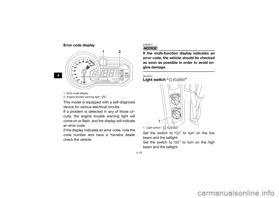
Error code display
This model is equipped with a self-diagnosis
device for various electrical circuits.
If a problem is detected in any of those cir-
cuits, the engine trouble warning light will
come on or flash, and the display will indicate
an error code.
If the display indicates an error code, note the
code number and have a Yamaha dealer
check the vehicle.
NOTICEECB00812If the multi-function display indicates an
error code, the vehicle should be checked
as soon as possible in order to avoid en-
gine damage. EBU35470Light switch “ / / ”Set the switch to “ ” to turn on the low
beam and the taillight.
Set the switch to “ ” to turn on the high
beam and the taillight.
1. Error code display
2. Engine trouble warning light “ ”
12
1. Light switch “ / / ”
L
H
1
L
HLH
U2HC7ME0.book Page 16 Tuesday, April 19, 2016 10:33 AM
Page 87 of 208

5-2
5
Engine oil• Check oil level.
• Fill with oil to proper level if necessary.
5-5, 8-15
Drivetrain • Check front differential, transmission case, and rear final
gear for leakage. 5-6, 5-6, 5-7, 8-26,
8-29, 8-31
Coolant • Check coolant level in reservoir.
• Fill with coolant if necessary. 5-6, 8-33
Accelerator pedal • Check free play and for proper operation. 5-7
Seat belts • Check for proper operation and belt wear. 5-7
Passenger handhold • Check for stability and proper fastening. 5-7, 7-8
Steering • Check for proper operation. 5-7
Shift lever • Check for proper operation. 5-8
Fittings and fasteners • Check all fittings and fasteners. 5-8
Instruments, lights and
switches • Check operation, and correct if necessary.
5-8, 8-63, 8-64
Wheels and tires • Check tire pressure and for wear and damage. 5-8, 8-54, 8-56
Axle boots • Check for damage. 8-35
ITEM
ROUTINE PAGE
U2HC7ME0.book Page 2 Tuesday, April 19, 2016 10:33 AM
Page 89 of 208
5-4
5
Clutch fluid
Depress and release the clutch pedal five
times. Check to see if any fluid is leaking out
of the hoses, reservoir, or master cylinder.
Check the clutch fluid level and correct if nec-
essary. (See page 8-45.)TIPIf any leakage is found, or if the clutch pedal
offers little resistance, have a Yamaha dealer
service the vehicle. EBU33200FuelMake sure there is sufficient fuel in the tank.
WARNING
EWB02522Gasoline and gasoline vapors are ex-
tremely flammable. To avoid fires and ex-
plosions and to reduce the risk of injury
when refueling, follow these instructions.
1. Before refueling, turn off the engine and
be sure that no one is sitting in the vehi-
cle.
Never refuel while smoking, or while in
the vicinity of sparks, open flames, or
other sources of ignition such as the pilot
lights of water heaters and clothes dry-
ers.
2. Do not overfill the fuel tank. Because fuel expands when it heats up, heat from the
engine or the sun can cause fuel to spill
out of the fuel tank.
3. Wipe up any spilled fuel immediately.
4. Be sure the fuel tank cap is closed se- curely.
WARNING
EWB02532Gasoline is poisonous and can cause inju-
ry or death. Handle gasoline with care.
Never siphon gasoline by mouth. If you
should swallow some gasoline or inhale a
lot of gasoline vapor, or get some gasoline
in your eyes, see your doctor immediately.
U2HC7ME0.book Page 4 Tuesday, April 19, 2016 10:33 AM
Page 93 of 208

5-8
5
EBU35690Shift leverThe shift lever should move smoothly both
forward and backwards and return to its orig-
inal position after a gear change is made.
Check the shift lever and transmission for
roughness before starting off.TIPThe engine may need to be started for the
transmission to engage gears. EBU35700Fittings and fastenersAlways check the tightness of chassis and
wheel fittings and fasteners before starting
off. Take the vehicle to a Yamaha dealer or re-
fer to the Service Manual for correct tighten-
ing torque.EBU31840Instruments, lights and switchesCheck that all instruments, lights and switch-
es are working properly. Correct if necessary.
EBU31851Control cablesWhen driving in cold weather, always make
sure all control cables work smoothly before
starting off. WARNING! Control cables can
freeze in cold weather and you could be
unable to control the vehicle.
[EWB03280]
EBU35331
TiresCheck tire pressure regularly to make sure it
is at the recommended specifications. Also
check for wear and damage.
Tire pressure
Use the tire pressure gauge to check and ad-
just tire pressures when the tires are cold. Tire
pressures must be equal on both sides.
WARNING! Operation of this vehicle with improper tire pressure may cause severe
injury or death from loss of control or roll-
over. Tire pressure below the minimum
U2HC7ME0.book Page 8 Tuesday, April 19, 2016 10:33 AM
Page 162 of 208
8-36
8
The porcelain insulator around the center
electrode of each spark plug should be a me-
dium-to-light tan color (the ideal color when
the vehicle is ridden normally), and all spark
plugs installed in the engine should have a
similar color. If any spark plug shows a dis-
tinctly different color, the engine could be op-
erating improperly. Do not attempt to
diagnose such problems yourself. Instead,
have a Yamaha dealer check the vehicle.
If a spark plug shows signs of electrode ero-
sion and excessive carbon or other deposits,
it should be replaced.
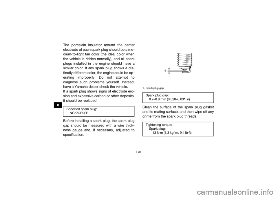
Before installing a spark plug, the spark plug
gap should be measured with a wire thick-
ness gauge and, if necessary, adjusted to
specification.Clean the surface of the spark plug gasket
and its mating surface, and then wipe off any
grime from the spark plug threads.Specified spark plug:
NGK/CR9EB
1. Spark plug gapSpark plug gap:0.7–0.8 mm (0.028–0.031 in)
Tightening torque: Spark plug:13 N·m (1.3 kgf·m, 9.4 lb·ft)
1
U2HC7ME0.book Page 36 Tuesday, April 19, 2016 10:33 AM
Page 205 of 208

12-1
12
INDEX
AAccelerator pedal ......................................................... 4-18
Accelerator pedal, checking ........................................ 8-49
Accelerator pedal, Pre-operation check ........................ 5-7
Air filter ......................................................................... 8-37
Air filter case hoses, cleaning ...................................... 8-41
Auxiliary DC jack .......................................................... 4-46
Axle boots .................................................................... 8-35BBasic guide for safe use ................................................ 7-1
Battery, Periodic maintenance .................................... 8-57
Bead lock, checking and tightening (YXZ10YMSH) .... 8-55
Brake and clutch fluid levels, checking ....................... 8-45
Brake fluid, replacing ................................................... 8-47
Brake light switch, adjusting ........................................ 8-50
Brake pedal .................................................................. 4-19
Brake pedal, checking ................................................. 8-48
Brakes, Periodic maintenance ..................................... 8-44
Brakes, Pre-operation check ......................................... 5-3CCable, inspecting and lubrication ................................ 8-51
Cargo bed .................................................................... 4-29
Cleaning ......................................................................... 9-1
Clutch pedal ................................................................. 4-19
Clutch pedal, checking ................................................ 8-47
Clutch, Pre-operation check .......................................... 5-3
Control cables, Pre-operation check ............................. 5-8
Coolant, Periodic maintenance ................................... 8-33
Coolant, Pre-operation check ........................................ 5-6Coolant temperature warning light ................................ 4-4
Cup holders ................................................................. 4-28
DDifferential gear lock indicator light ............................... 4-3
Differential gear oil, Periodic maintenance .................. 8-31
Differential gear, Pre-operation check ........................... 5-7
Doors ........................................................................... 4-22
Drive mode, selecting .................................................... 6-7
Driver seat position ...................................................... 4-24
Drive shaft universal joint, lubrication .......................... 8-53
Drivetrain icon ................................................................ 4-3EEngine break-in .............................................................. 6-1
Engine oil and oil filter, Periodic maintenance ............. 8-15
Engine oil, Pre-operation check .................................... 5-5
Engine trouble warning light .......................................... 4-5
EPS warning light .......................................................... 4-5FFinal gear oil, Periodic maintenance ............................ 8-29
Final gear, Pre-operation check .................................... 5-6
Fittings and fasteners, Pre-operation check ................. 5-8
Flag pole bracket ......................................................... 4-30
Front and rear brake pads, checking .......................... 8-44
Fuel, Pre-operation check ............................................. 5-4
Fuel tank cap ............................................................... 4-21
Fuse, replacing ............................................................ 8-61GGlove compartment ..................................................... 4-25HHeadlight beam, adjusting ........................................... 8-64
Headlights .................................................................... 8-63
U2HC7ME0.book Page 1 Tuesday, April 19, 2016 10:33 AM
Page 206 of 208

12-2
12
Helmet indicator light .....................................................4-6
High beam indicator light ............................................... 4-3
Hood ............................................................................ 8-10IIdentification number records ...................................... 11-1
Indicator lights and warning lights ................................. 4-2
Instruments, lights and switches, Pre-operation check ........................................................................... 5-8JJump-starting ............................................................... 8-60LLabel locations ............................................................... 1-1
Light switch .................................................................. 4-16
Loading ..........................................................................6-9MMain switch .................................................................... 4-1
Maintenance and lubrication chart ................................8-6
Maintenance chart, emission control system ................ 8-4
Model label ................................................................... 11-1
Multi-function meter unit ................................................ 4-7NNeutral indicator light .....................................................4-2OOn-Command drive knob ............................................ 4-17
Owner’s manual and tool kit .......................................... 8-2PPanels .......................................................................... 8-10
Parking ........................................................................... 6-9
Parking brake indicator light .......................................... 4-3
Parking brake lever ...................................................... 4-20
Parking brake lever free play, adjusting ....................... 8-49 Parking brake pads, checking ..................................... 8-45
Passenger handhold, Pre-operation check ................... 5-7
Pedal, lubrication ......................................................... 8-51
RRear knuckle upper and lower pivot, lubrication ......... 8-53
Reverse gear lock lever ................................................ 4-18
Reverse indicator light ................................................... 4-2SSafety information .......................................................... 2-1
Seat belt indicator light .................................................. 4-6
Seat belts ..................................................................... 4-25
Seat belts, Pre-operation check .................................... 5-7
Seats ............................................................................ 4-22
Shift lever ..................................................................... 4-21
Shift lever operation and reverse driving ....................... 6-3
Shift lever, Pre-operation check .................................... 5-8
Shift timing indicator light .............................................. 4-4
Shock absorber assemblies, adjusting the front ......... 4-30
Shock absorber assemblies, adjusting the rear ........... 4-38
Spark arrester, cleaning ............................................... 8-42
Spark plugs, checking ................................................. 8-35
Specifications .............................................................. 10-1
Stabilizer bushes, checking ......................................... 8-52
Starting the engine ......................................................... 6-2
Steering, Pre-operation check ....................................... 5-7
Steering shaft, lubrication ............................................ 8-54
Steering wheel position ................................................ 4-24
Storage .......................................................................... 9-2
Storage compartments ................................................ 4-26TTail/brake light ............................................................. 8-64
Tire, replacing .............................................................. 8-55
U2HC7ME0.book Page 2 Tuesday, April 19, 2016 10:33 AM