warning YAMAHA YXZ1000R SS 2018 Owner's Manual
[x] Cancel search | Manufacturer: YAMAHA, Model Year: 2018, Model line: YXZ1000R SS, Model: YAMAHA YXZ1000R SS 2018Pages: 224, PDF Size: 5.68 MB
Page 46 of 224

4-8
4
The engine may not start even though the
starter motor operates. If the YCC-S system stops working correctly
while driving, the YCC-S warning light will
come on. If this occurs, it may be impossible
to shift out of the gear you are in; and the
clutch may stay engaged, so a shuddering
sensation may be felt when you come to a
stop. Stop the vehicle on level ground safely
off the main trail, and have the YCC-S system
serviced by a Yamaha dealer before further
operation.TIPIf shifting into neutral is impossible using the
shift paddles and drive select lever, proceed
as follows if it is nece ssary to move the vehi-
cle after it has stopped. 1. Turn the key to “ ” (off).
2. Remove panel B (page 8-11). 3. While rocking the vehicle back and forth,
push the shift rod and shift arm pivot
downward (or upward if the transmission
was in reverse) until the transmission is in
neutral.
WARNING
EWB04171Turn the key to “ ” (off) before attempt-
ing to manipulate the shift rod. Other-
wise, the shift actuator may operate
unexpectedly and cause injury.1. Shift arm pivot
2. Shift rod
3. Neutral position
1
2
3
5 5
4
3
2
1
N
R 5
4
3
2
1
N
R
UB0F7AE0.book Page 8 Monday, November 6, 2017 2:30 PM
Page 53 of 224
4-15
4
below 0 °C (32 °F), “LO” will be displayed.
When the coolant temperature is between
122 °C (252 °F) and 128 °C (263 °F), the cool-
ant temperature display will flash. In this case,
stop the vehicle in a safe place and let it idle
for 10 minutes. If the message “HI” flashes,
stop the engine and let it cool. (See page
8-69.)TIP The coolant temperature display can be set
to “°C” or “°F”. To switch the temperature
units, turn the key to “ ” (off), then hold
the “RESET” button pushed and turn the
key to “ ” (on).
The radiator fan turns on and off automati-
cally according to the coolant temperature.
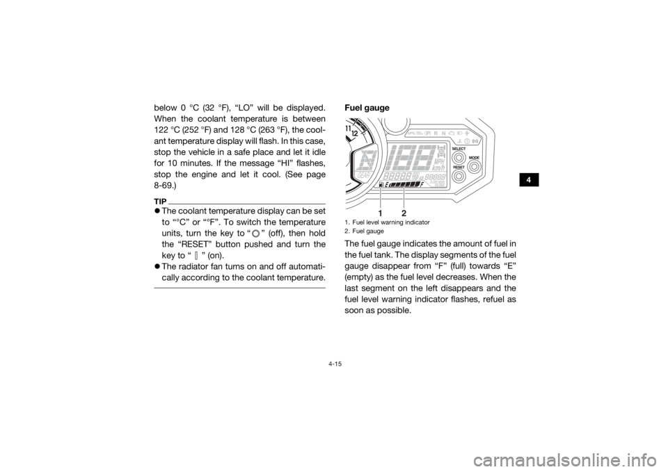
Fuel gauge
The fuel gauge indicates the amount of fuel in
the fuel tank. The display segments of the fuel
gauge disappear from “F” (full) towards “E”
(empty) as the fuel level decreases. When the
last segment on the left disappears and the
fuel level warning indicator flashes, refuel as
soon as possible.1. Fuel level warning indicator
2. Fuel gauge
1
2
UB0F7AE0.book Page 15 Monday, November 6, 2017 2:30 PM
Page 54 of 224
4-16
4
TIPThis fuel gauge is equipped with a self-diag-
nosis system. If a problem is detected in an
electrical circuit, all the display segments and
fuel level warning indicator start flashing. If
this occurs, have a Yamaha dealer check the
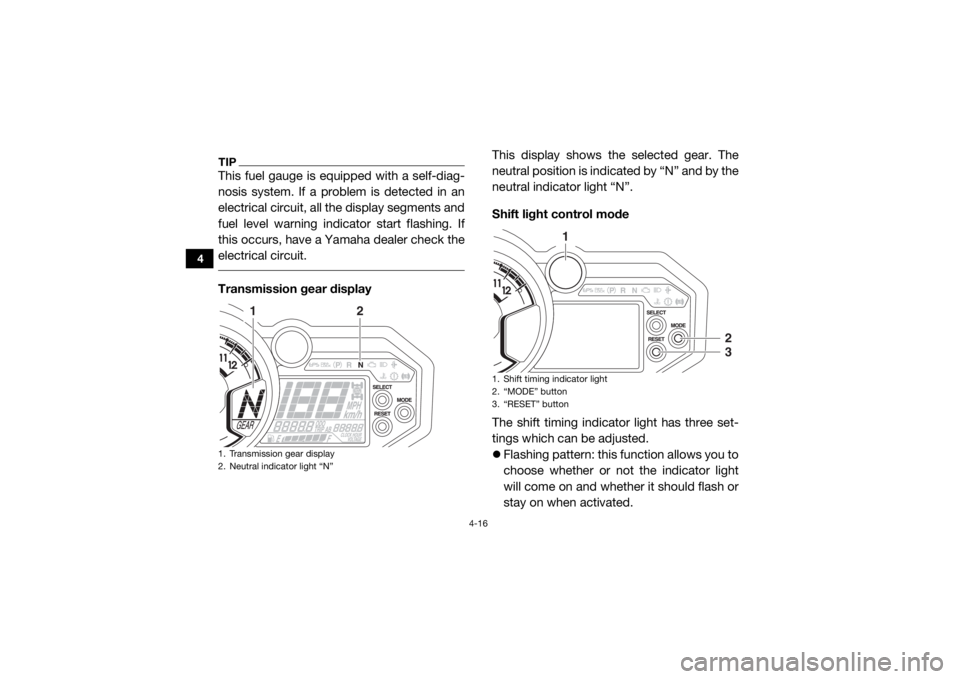
electrical circuit. Transmission gear displayThis display shows the selected gear. The
neutral position is indicated by “N” and by the
neutral indicator light “N”.
Shift light control mode
The shift timing indicator light has three set-
tings which can be adjusted.
Flashing pattern: this function allows you to
choose whether or not the indicator light
will come on and whether it should flash or
stay on when activated.1. Transmission gear display
2. Neutral indicator light “N”
1
2
1. Shift timing indicator light
2. “MODE” button
3. “RESET” button
1
23
UB0F7AE0.book Page 16 Monday, November 6, 2017 2:30 PM
Page 57 of 224

4-19
4
Error code display
This model is equipped with a self-diagnosis
device for various electrical circuits.
If a problem is detected in any of those cir-
cuits, the engine trouble warning light and/or
the YCC-S system warning light will come on
or flash, and the display will indicate an error
code.
TIPYCC-S system error codes are displayed
only when the engine is stopped.
If the display indicates an error code, note
the code number and have a Yamaha deal-
er check the vehicle. NOTICEECB00812If the multi-function display indicates an
error code, the vehicle should be checked
as soon as possible in order to avoid en-
gine damage.
1. Error code display
2. YCC-S system error code display
3. Engine trouble warning light “ ”
4. YCC-S system warning light “ ”
1
2
3
4
UB0F7AE0.book Page 19 Monday, November 6, 2017 2:30 PM
Page 65 of 224
4-27
4
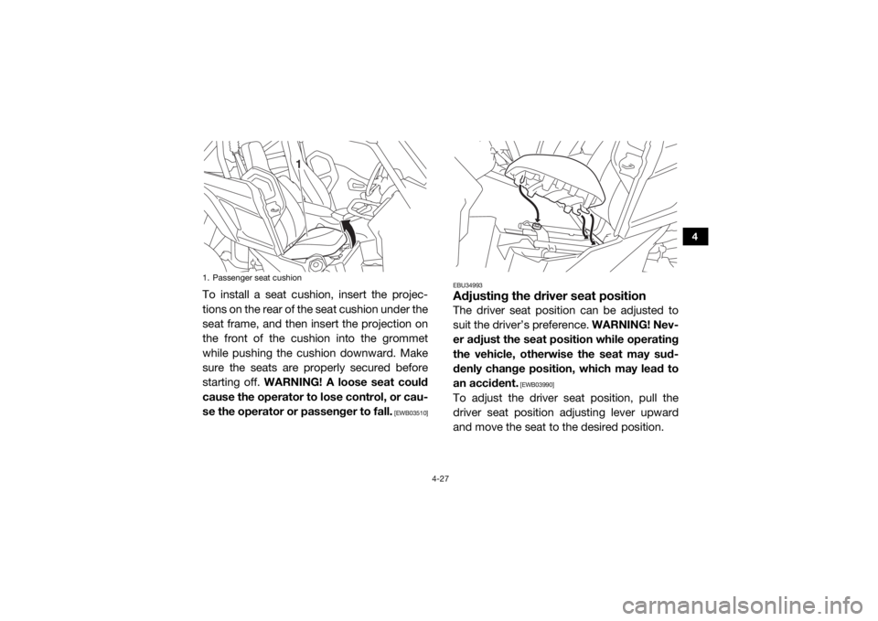
To install a seat cushion, insert the projec-
tions on the rear of the seat cushion under the
seat frame, and then insert the projection on
the front of the cushion into the grommet
while pushing the cushion downward. Make
sure the seats are properly secured before
starting off. WARNING! A loose seat could
cause the operator to lose control, or cau-
se the operator or passenger to fall.
[EWB03510] EBU34993
Adjusting the driver seat positionThe driver seat position can be adjusted to
suit the driver’s preference.
WARNING! Nev-
er adjust the seat position while operating
the vehicle, otherwise the seat may sud-
denly change position, which may lead to
an accident.
[EWB03990]
To adjust the driver seat position, pull the
driver seat position adjusting lever upward
and move the seat to the desired position.
1. Passenger seat cushion
1
UB0F7AE0.book Page 27 Monday, November 6, 2017 2:30 PM
Page 66 of 224
4-28
4
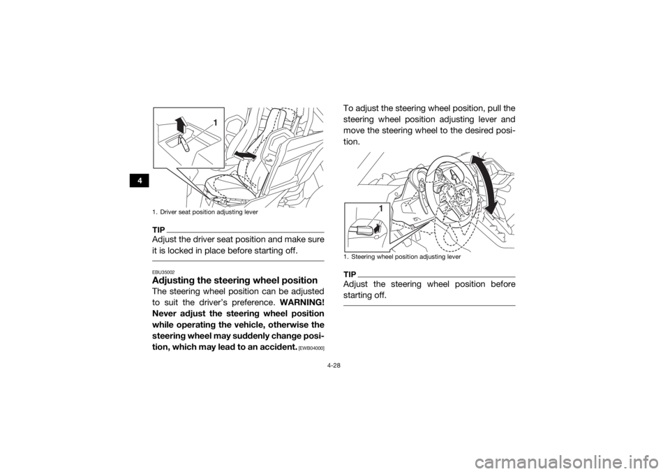
TIPAdjust the driver seat position and make sure
it is locked in place before starting off. EBU35002Adjusting the steering wheel positionThe steering wheel position can be adjusted
to suit the driver’s preference. WARNING!
Never adjust the steering wheel position
while operating the vehicle, otherwise the
steering wheel may suddenly change posi-
tion, which may lead to an accident.
[EWB04000]
To adjust the steering wheel position, pull the
steering wheel position adjusting lever and
move the steering wheel to the desired posi-
tion.TIPAdjust the steering wheel position before
starting off.
1. Driver seat position adjusting lever
1
1. Steering wheel position adjusting lever
1
UB0F7AE0.book Page 28 Monday, November 6, 2017 2:30 PM
Page 69 of 224
4-31
4
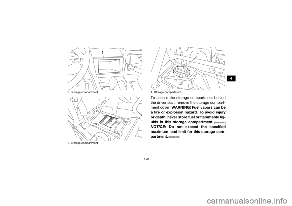
To access the storage compartment behind
the driver seat, remove the storage compart-
ment cover. WARNING! Fuel vapors can be
a fire or explosion hazard. To avoid injury
or death, never store fuel or flammable liq-
uids in this storage compartment.
[EWB03230]
NOTICE: Do not exceed the specified
maximum load limit for this storage com-
partment.
[ECB02090]
1. Storage compartment
1. Storage compartment
1
1
1. Storage compartment
1
UB0F7AE0.book Page 31 Monday, November 6, 2017 2:30 PM
Page 70 of 224
4-32
4
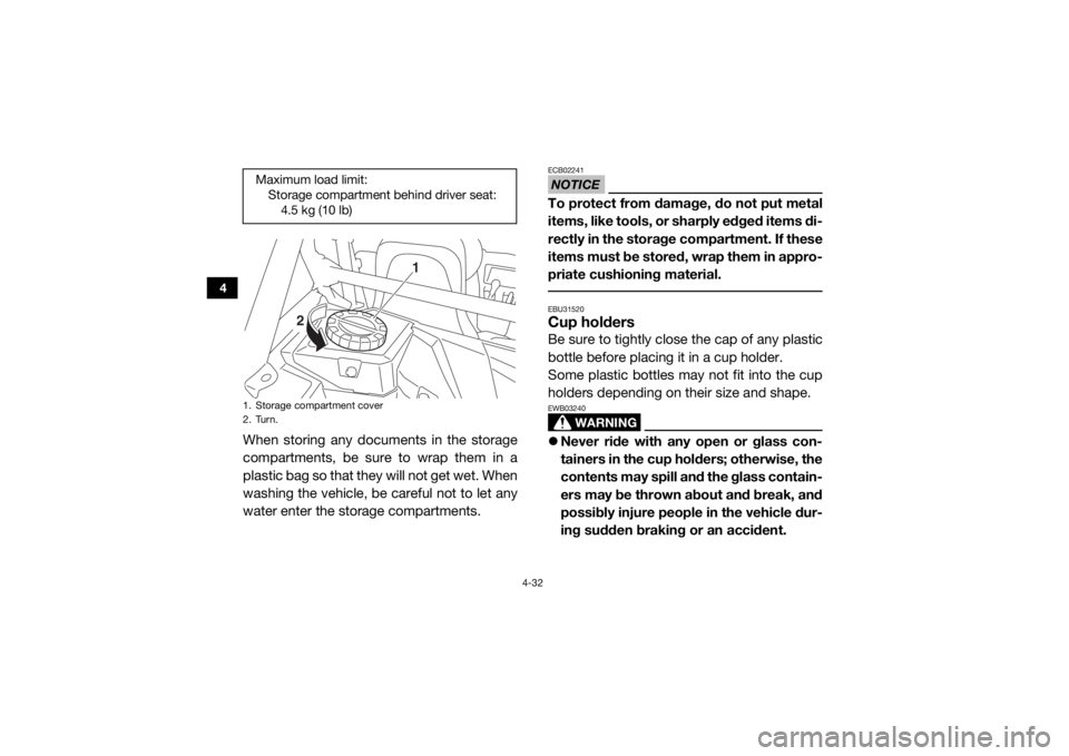
When storing any documents in the storage
compartments, be sure to wrap them in a
plastic bag so that they will not get wet. When
washing the vehicle, be careful not to let any
water enter the storage compartments.
NOTICEECB02241To protect from damage, do not put metal
items, like tools, or sharply edged items di-
rectly in the storage compartment. If these
items must be stored, wrap them in appro-
priate cushioning material. EBU31520Cup holdersBe sure to tightly close the cap of any plastic
bottle before placing it in a cup holder.
Some plastic bottles may not fit into the cup
holders depending on their size and shape.
WARNING
EWB03240 Never ride with any open or glass con-
tainers in the cup holders; otherwise, the
contents may spill and the glass contain-
ers may be thrown about and break, and
possibly injure people in the vehicle dur-
ing sudden braking or an accident.
Maximum load limit:
Storage compartment behind driver seat:4.5 kg (10 lb)1. Storage compartment cover
2. Turn.
1
2
UB0F7AE0.book Page 32 Monday, November 6, 2017 2:30 PM
Page 71 of 224

4-33
4
Do not place any other items than seal-
able plastic containers in the cup hold-
ers; otherwise, they may be thrown
about and possibly injure people in the
vehicle during sudden braking or an ac-
cident. EBU35020Cargo bed
WARNING
EWB03250Never carry passengers in the cargo
bed.
Do not exceed the specified maximum
load limits. Heavier cargo could cause
loss of control because of improper
weight balance.
There are four cargo hooks in the cargo bed.
For additional loading information, see page
6-12.
1. Cup holder
1
1. Cargo hookMaximum load limit: 136.0 kg (300 lb)
1
1
UB0F7AE0.book Page 33 Monday, November 6, 2017 2:30 PM
Page 72 of 224

4-34
4
EBU35660Flag pole bracketThis model is equipped with a flag pole brack-
et.NOTICEECB03010Do not use the flag pole bracket as a cargo
hook.
EBU36465Front shock absorbersThe shock absorber assemblies are equipped
with a spring preload adjusting nut, a cross-
over adjusting nut (for YXZ10YESJ), a re-
bound damping force adjusting screw (for
YXZ10YEXJ), a high speed rebound damping
force adjusting bolt (for YXZ10YESJ), a low
speed rebound damping force adjusting
screw (for YXZ10YESJ), a high speed com-
pression damping force adjusting bolt, and a
low speed compression damping force ad-
justing screw.
WARNING
EWB04140Suspension components become hot
during operation. Never touch the com-
pression damping force adjusting bolt
and screw, the rebound damping force
adjusting bolt and screw, or the oil reser-
voir with your bare hand or skin until
suspension components have cooled.
1. Flag pole bracket
1
1
UB0F7AE0.book Page 34 Monday, November 6, 2017 2:30 PM