warning light YAMAHA YXZ1000R SS 2019 User Guide
[x] Cancel search | Manufacturer: YAMAHA, Model Year: 2019, Model line: YXZ1000R SS, Model: YAMAHA YXZ1000R SS 2019Pages: 218, PDF Size: 9.48 MB
Page 94 of 218

5-8
5
EBU36672YCC-S clutchCheck the YCC-S clutch fluid level and cor-
rect if necessary. (See page 8-48.)
Check the operation of the drive select lever
and shift paddles at the start of each drive.TIPIf the YCC-S clutch fluid level was low, be
sure to check the clutch system for leak-
age.
If any leakage is found, or if shifting is not
smooth, have a Yamaha dealer service the
vehicle. EBU35700Fittings and fastenersAlways check the tightness of chassis and
wheel fittings and fasteners before starting
off. Take the vehicle to a Yamaha dealer or re-
fer to the Service Manual for correct tighten-
ing torque.
EBU31840Instruments, lights and switchesCheck that all instruments, lights and switch-
es are working properly. Correct if necessary.EBU31851Control cablesWhen driving in cold weather, always make
sure all control cables work smoothly before
starting off. WARNING! Control cables can
freeze in cold weather and you could be
unable to control the vehicle.
[EWB03280]
EBU37892
TiresCheck and adjust the tire pressure before
each ride. Check tires for wear and damage.
UB5H7AE0.book Page 8 Wednesday, July 4, 2018 1:37 PM
Page 98 of 218

6-2
6
10–20 hours:
Avoid prolonged operation above 6300 r/min.
After break-in:
The vehicle may now be operated normally.EBU36560Starting the engine1. Turn the key to “ ” (on).NOTICEECB03340The coolant temperature warning light,
YCC-S system warning light, and engine
trouble warning light should come on, then
go off.
The EPS warning light should come on,
then go off when the engine is started.
To avoid possible damage, do not operate
the vehicle if a warning light does not work
as described above. 2. Press the brake pedal.
3. Shift the transmission into neutral.
When the transmission is in the neutral
position, the transmission gear display
shows “N” and the neutral indicator
light should come on.
The engine can be started in any gear if
the brake pedal is applied. However, it
is recommended to shift into neutral
before starting the engine.
4. With your foot off the accelerator pedal, start the engine by turning the key to “ ”
(start).
If the engine fails to start, release the key, and
then try starting it again. Wait a few seconds
before the next attempt. Each attempt should
be as short as possible, to preserve battery
energy. NOTICE: Do not crank the engine
more than 5 seconds on each attempt, or
starter damage could occur. Wait at least
5 seconds between each operation of the
electric starter to let it cool.
[ECB02140]
Do not turn the key to the “ ” (start) position
with the engine running; otherwise, damage
to the electric starter may result.
UB5H7AE0.book Page 2 Wednesday, July 4, 2018 1:37 PM
Page 102 of 218

6-6
6
To drive in reverse
WARNING
EWB03300Before you shift into reverse, make sure
there are no obstacles or people behind
you. When it is safe to proceed, go slowly.
Hitting an obstacle or person could result
in serious injury or death. 1. Stop the vehicle and continue to apply the brake pedal.
2. Check behind you.
3. Shift the transmission into reverse.
TIP To shift into reverse, the engine must be
running and at idle speed.
When in reverse, the transmission gear dis-
play should show “R” and the reverse indi-
cator light should come on.
The reverse buzzer will sound while the
transmission is in reverse. 4. Release the parking brake (if applied).1. Drive select lever
2. Reverse gear
1
2
UB5H7AE0.book Page 6 Wednesday, July 4, 2018 1:37 PM
Page 104 of 218

6-8
6
the engine is not warmed up or is overheat-
ing.
the driver seat belt is not latched.
the differential gear is locked (“DIFF LOCK”
is selected) or the differential gear lock indi-
cator is flashing.
the parking brake is applied.
an engine or system malfunction is detect-
ed (a warning light is on). To activate the launch system1. Confirm that the front wheels and steer-
ing wheel are pointed straight ahead.
2. Shift the transmission into first gear.
3. While pressing the brake pedal, pull both
shift paddles toward you and hold them
in that position. The launch system indi-
cator light will come on, and the launch
system enters standby mode. 4. While checking in front of you for obsta-
cles or anything that may cross your
path, release the brake pedal, and then
press the accelerator pedal to rev the en-
gine to the desired launch engine speed.
TIPThe engine speed at launch must be be-
tween 5000–10000 r/min.
If you release one shift paddle, or if a sys-
tem restriction is detected during standby
mode, the launch system indicator light will
begin to flash and the launch will be can-
celled.
UB5H7AE0.book Page 8 Wednesday, July 4, 2018 1:37 PM
Page 184 of 218

8-53
8
7. Turn the adjusting nut in direction (a) toincrease the free play or in direction (b) to
decrease the free play.
8. Tighten the locknut, and then slide the
rubber cover to its original position.
9. Install the panel.
EBU36620Brake light switchThe brake light, which is activated by the
brake pedal, should come on just before
braking takes effect. Since the brake light
switch is a component of the YCC-S system,
it must be adjusted by a Yamaha dealer, who
has the necessary professional knowledge
and experience.EBU35930Cable inspection and lubrication
WARNING
EWB03380Damaged cables could restrict operation,
which may cause an accident or injury. In-
spect control cables frequently and re-
place damaged cables. Corrosion can
result when the outer covering of control
cables becomes damaged. Cables can
also become frayed or kinked.
1. Rubber cover
2. Adjusting nut
3. Locknut
1
(b)
(a)
3
2
UB5H7AE0.book Page 53 Wednesday, July 4, 2018 1:37 PM
Page 196 of 218

8-65
8
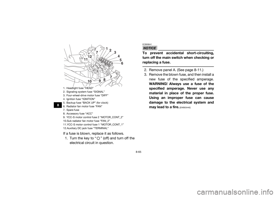
If a fuse is blown, replace it as follows.1. Turn the key to “ ” (off) and turn off the electrical circuit in question.
NOTICEECB00641To prevent accidental short-circuiting,
turn off the main switch when checking or
replacing a fuse. 2. Remove panel A. (See page 8-11.)
3. Remove the blown fuse, and then install anew fuse of the specified amperage.
WARNING! Always use a fuse of the
specified amperage. Never use any
material in place of the proper fuse.
Using an improper fuse can cause
damage to the electrical system and
may lead to a fire.
[EWB03440]
1. Headlight fuse “HEAD”
2. Signaling system fuse “SIGNAL”
3. Four-wheel-drive motor fuse “DIFF”
4. Ignition fuse “IGNITION”
5. Backup fuse “BACK UP” (for clock)
6. Radiator fan motor fuse “FAN”
7. Spare fuse
8. Accessory fuse “ACC”
9. YCC-S motor control fuse 2 “MOTOR_CONT_2”
10.Sub radiator fan motor fuse “FAN_2”
11.YCC-S motor control fuse 1 “MOTOR_CONT_1”
12.Auxiliary DC jack fuse “TERMINAL”
56
7
7
12
11
10 98 4
3
2
1
UB5H7AE0.book Page 65 Wednesday, July 4, 2018 1:37 PM
Page 200 of 218

8-69
8
procedure for making checks. If your vehicle
requires any repair, take it to a Yamaha deal-
er.
The skilled technicians at a Yamaha dealer-
ship have the tools, experience, and know-
how to properly service your vehicle. Use only
genuine Yamaha parts on your vehicle. Imita-
tion parts may look like Yamaha parts, but
they are often inferior. Consequently, they
have a shorter service life and can lead to ex-
pensive repair bills.
WARNING
EWB03450When checking the fuel system, do not
smoke and make sure there are no open
flames or sparks in the area, including pilot
lights from water heaters or furnaces.
Gasoline or gasoline vapors can ignite or
explode, causing severe injury or property
damage. UB5H7AE0.book Page 69 Wednesday, July 4, 2018 1:37 PM
Page 210 of 218

10-5
10
Rear suspension:Type:Double wishbone
Spring:
Coil spring
Shock absorber: Gas-hydraulic damper
Wheel travel: 432 mm (17.0 in)Electrical system:System voltage:12 V
Ignition system: TCI
Charging system:
AC magnetoBattery:Model:U1-H11L
Voltage, capacity:
12 V, 28.0 AhLights:Headlight:LED
Brake/tail light:
LED
Auxiliary light: LED [YXZ10YESK (LE model)]
Interior light: LED [YXZ10YESK (LE model)] Meter lighting:
LED
Neutral indicator light: LED
High beam indicator light:
LED
Reverse indicator light: LED
Coolant temperature warning light: LED
Parking brake indicator light:
LED
Engine trouble warning light: LED
Differential gear lock indicator light: LED
EPS warning light:
LED
Helmet reminder light: 0.8 W
Seat belt reminder light: 0.8 W
Shift timing indicator light:
LED
Half clutch indicator light: LED
Launch system indicator light: LED
YCC-S system warning light:
LED
UB5H7AE0.book Page 5 Wednesday, July 4, 2018 1:37 PM
Page 215 of 218

12-1
12
INDEX
AAccelerator pedal ......................................................... 4-22
Accelerator pedal, checking ........................................ 8-51
Accelerator pedal, Pre-operation check ........................ 5-6
Air filter ......................................................................... 8-40
Air filter case hoses, cleaning ...................................... 8-44
Auxiliary DC jack .......................................................... 4-55
Axle boots .................................................................... 8-38BBasic guide for safe use ................................................ 7-1
Battery, Periodic maintenance .................................... 8-59
Bead lock, checking and tightening (for SE/LE models) ..................................................... 8-57
Brake and YCC-S clutch fluid levels, checking ........... 8-48
Brake fluid, replacing ................................................... 8-50
Brake light switch ........................................................ 8-53
Brake pedal .................................................................. 4-22
Brake pedal, checking ................................................. 8-51
Brakes, Periodic maintenance ..................................... 8-47
Brakes, Pre-operation check ......................................... 5-3
Brake/tail light .............................................................. 8-68CCable, inspecting and lubrication ................................ 8-53
Cargo bed .................................................................... 4-32
Cleaning ......................................................................... 9-1
Control cables, Pre-operation check ............................. 5-8
Coolant, Periodic maintenance ................................... 8-36
Coolant, Pre-operation check ........................................ 5-6
Coolant temperature warning light ................................ 4-4 Cup holders ................................................................. 4-31
DData recording, vehicle ................................................ 11-2
Differential gear lock indicator light ............................... 4-3
Differential gear oil, Periodic maintenance .................. 8-33
Differential gear, Pre-operation check ........................... 5-6
Doors ........................................................................... 4-25
Drive mode, selecting .................................................. 6-10
Driver seat position ...................................................... 4-27
Drive select lever and shift paddles ............................. 4-24
Drive select lever and shift paddles, Pre-operation
check ........................................................................... 5-7
Drive shaft universal joint, lubrication .......................... 8-56
Drivetrain icon ................................................................ 4-3
Dynamic clutch engagement ......................................... 6-7EEngine break-in .............................................................. 6-1
Engine oil and oil filter, Periodic maintenance ............. 8-18
Engine oil, Pre-operation check .................................... 5-5
Engine trouble warning light .......................................... 4-5
EPS warning light .......................................................... 4-5FFinal gear oil, Periodic maintenance ............................ 8-31
Final gear, Pre-operation check .................................... 5-6
Fittings and fasteners, Pre-operation check ................. 5-8
Flag pole bracket ......................................................... 4-33
Four–wheel drive knob (On–Command 4WD) ............. 4-21
Front and rear brake pads, checking .......................... 8-47
Fuel, Pre-operation check ............................................. 5-3
Fuel tank cap ............................................................... 4-25
Fuse, replacing ............................................................ 8-64
UB5H7AE0.book Page 1 Wednesday, July 4, 2018 1:37 PM
Page 216 of 218

12-2
12
GGlove compartment ..................................................... 4-30HHalf clutch indicator light ............................................... 4-6
Headlight beam, adjusting ........................................... 8-67
Headlights .................................................................... 8-67
Helmet reminder light .....................................................4-9
High beam indicator light ............................................... 4-3
Hood ............................................................................ 8-11IIdentification number records ...................................... 11-1
Indicator lights and warning lights ................................. 4-2
Instruments, lights and switches, Pre-operation check ........................................................................... 5-8
Interior lights (for LE models) ....................................... 8-68
Interior light switch (for LE models) ..............................4-20JJump-starting ............................................................... 8-63LLabel locations ............................................................... 1-1
Launch system indicator light ........................................ 4-7
Launch system operation ............................................... 6-7
Light switch .................................................................. 4-20
Loading ........................................................................6-12MMain switch .................................................................... 4-1
Maintenance and lubrication chart ................................8-6
Maintenance chart, emission control system ................ 8-4
Maintenance charts ....................................................... 8-4
Model label ................................................................... 11-1
Multi-function meter unit .............................................. 4-10
NNeutral indicator light ..................................................... 4-2OOwner’s Manual and tool kit .......................................... 8-2PPanels .......................................................................... 8-11
Parking ......................................................................... 6-12
Parking brake indicator light .......................................... 4-3
Parking brake lever ...................................................... 4-23
Parking brake lever free play, adjusting ....................... 8-52
Parking brake pads, checking ..................................... 8-48
Passenger handhold, Pre-operation check ................... 5-7
Pedal, lubrication ......................................................... 8-54RRear knuckle upper and lower pivot, lubrication ......... 8-56
Rearview mirror (for SE/LE models) ............................. 4-29
Reverse indicator light ................................................... 4-2SSafety information .......................................................... 2-1
Seat belt reminder light .................................................. 4-9
Seat belts ..................................................................... 4-29
Seat belts, Pre-operation check .................................... 5-7
Seats ............................................................................ 4-26
Shifting and reverse driving ........................................... 6-3
Shift timing indicator light .............................................. 4-4
Shock absorbers, front ................................................ 4-33
Shock absorbers, rear ................................................. 4-44
Spark arrester, cleaning ............................................... 8-45
Spark plugs, checking ................................................. 8-38
Specifications .............................................................. 10-1
Stabilizer bushes, checking ......................................... 8-54
UB5H7AE0.book Page 2 Wednesday, July 4, 2018 1:37 PM