light YAMAHA YXZ1000R SS 2019 Owner's Guide
[x] Cancel search | Manufacturer: YAMAHA, Model Year: 2019, Model line: YXZ1000R SS, Model: YAMAHA YXZ1000R SS 2019Pages: 218, PDF Size: 9.48 MB
Page 105 of 218

6-9
6
If the indicator light is flashing, release the
accelerator pedal and let the engine return
to idle speed. When the indicator light goes
off, you may start off normally or retry acti-
vating the launch system. 5. When ready, release both shift paddles at the same time and further press the ac-
celerator pedal to launch the vehicle.TIPWhen the clutch has completely engaged, the
launch system and the launch system indica-
tor light will turn off. NOTICEECB03430Do not make consecutive launches with-
out allowing the clutch to cool down. Oth-
erwise, the clutch system may be
damaged. UB5H7AE0.book Page 9 Wednesday, July 4, 2018 1:37 PM
Page 106 of 218

6-10
6
EBU35061Selecting the drive modeThe vehicle handles differently in each of the drive modes: “2WD”, “4WD” and “DIFF LOCK”. For
example, the vehicle requires more effort to turn in “DIFF LOCK” than in “2WD”. Always stop the
vehicle before changing the position of th e On-Command drive knob. The drive mode icon
changes according to the selected drive mode. The drive mode icon and the “DIFF LOCK” indi-
cator light come on as follows:
Knob position Indication Drive mode
(none)
“2WD” (two-wheel drive): Drive power is supplied to the rear
wheels only.
“4WD” (four-wheel drive): Drive power is supplied to the
front and rear wheels.
“DIFF LOCK” (four-wheel drive with the differential gear
locked): Drive power is supplied to the front and rear wheels
and the differential gear is locked.
Unlike in four-wheel drive, all wheels turn at the same
speed.
UB5H7AE0.book Page 10 Wednesday, July 4, 2018 1:37 PM
Page 107 of 218

6-11
6
TIPWhen the knob is set to “DIFF LOCK” or “4WD ”, the drive mode icon and the indicator light
will flash until the differential gear is completely locked or unlocked.
Turning the steering wheel back and forth will help the differential gear lock to engage or dis-
engage.
To protect the drivetrain from damage, vehicle speed is limited until the differential gear lock
has properly transitioned. UB5H7AE0.book Page 11 Wednesday, July 4, 2018 1:37 PM
Page 143 of 218

8-12
8
Panel A
To remove the panel1. Unhook the projections as shown.
2. Disconnect the interior light couplers (forLE models), and then remove the panel.
1. Panel A
2. Panel B
1. Panel C
2. Panel D
1
2
1
2
1. Panel A
2. Projection
1
2
2
UB5H7AE0.book Page 12 Wednesday, July 4, 2018 1:37 PM
Page 144 of 218

8-13
8
For interior-light-equipped models
To install the panel1. Connect the interior light couplers. (ForLE models)
2. Place the panel in the original position. Panel B
To remove the panel
1. Remove the hood. (See page 8-11.)
2. Remove panel A.
3. Remove the top cover by removing the
quick fastener screw and the bolts.
1. Interior light coupler
1
1
UB5H7AE0.book Page 13 Wednesday, July 4, 2018 1:37 PM
Page 156 of 218

8-25
8
TIPAn oil filter wrench is available from a Yamaha
dealer. 7. Apply a light coat of clean engine oil to
the O-ring of the new oil filter cartridge.TIPMake sure that the O-ring is properly seated.
8. Install the new oil filter cartridge, and thentighten to the specified torque.
1. Oil filter cartridge
2. Oil filter wrench
2
1
1. O-ringTightening torque:Oil filter cartridge:17 N·m (1.7 kgf·m, 13 lb·ft)
1
UB5H7AE0.book Page 25 Wednesday, July 4, 2018 1:37 PM
Page 170 of 218

8-39
8
The porcelain insulator around the center
electrode of each spark plug should be a me-
dium-to-light tan color (the ideal color when
the vehicle is ridden normally), and all spark
plugs installed in the engine should have a
similar color. If any spark plug shows a dis-
tinctly different color, the engine could be op-
erating improperly. Do not attempt to
diagnose such problems yourself. Instead,
have a Yamaha dealer check the vehicle.
If a spark plug shows signs of electrode ero-
sion and excessive carbon or other deposits,
it should be replaced.
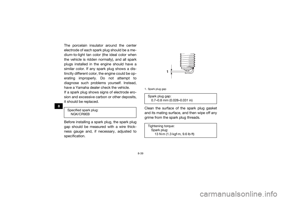
Before installing a spark plug, the spark plug
gap should be measured with a wire thick-
ness gauge and, if necessary, adjusted to
specification.Clean the surface of the spark plug gasket
and its mating surface, and then wipe off any
grime from the spark plug threads.Specified spark plug:
NGK/CR9EB
1. Spark plug gapSpark plug gap:0.7–0.8 mm (0.028–0.031 in)
Tightening torque: Spark plug:13 N·m (1.3 kgf·m, 9.6 lb·ft)
1
UB5H7AE0.book Page 39 Wednesday, July 4, 2018 1:37 PM
Page 177 of 218

8-46
8
2. Remove the tailpipe bolts.
3. Remove the tailpipe by pulling it out ofthe muffler, and then remove the gasket.
4. Tap the tailpipe lightly, and then use a wire brush to remove any carbon depos-
its from the spark arrester portion of the
tailpipe and inside of the tailpipe housing. 5. Install the gasket, and then insert the tail-
pipe into the muffler and align the bolt
holes.
6. Install the tailpipe bolts and tighten them
to the specified torque.
7. Install the tailpipe cover.1. Tailpipe bolt
1
1
1. Gasket
2. Spark arrester
3. TailpipeTightening torque:
Tailpipe bolt:10 N·m (1.0 kgf·m, 7.4 lb·ft)
2
1
3
UB5H7AE0.book Page 46 Wednesday, July 4, 2018 1:37 PM
Page 184 of 218

8-53
8
7. Turn the adjusting nut in direction (a) toincrease the free play or in direction (b) to
decrease the free play.
8. Tighten the locknut, and then slide the
rubber cover to its original position.
9. Install the panel.
EBU36620Brake light switchThe brake light, which is activated by the
brake pedal, should come on just before
braking takes effect. Since the brake light
switch is a component of the YCC-S system,
it must be adjusted by a Yamaha dealer, who
has the necessary professional knowledge
and experience.EBU35930Cable inspection and lubrication
WARNING
EWB03380Damaged cables could restrict operation,
which may cause an accident or injury. In-
spect control cables frequently and re-
place damaged cables. Corrosion can
result when the outer covering of control
cables becomes damaged. Cables can
also become frayed or kinked.
1. Rubber cover
2. Adjusting nut
3. Locknut
1
(b)
(a)
3
2
UB5H7AE0.book Page 53 Wednesday, July 4, 2018 1:37 PM
Page 196 of 218

8-65
8
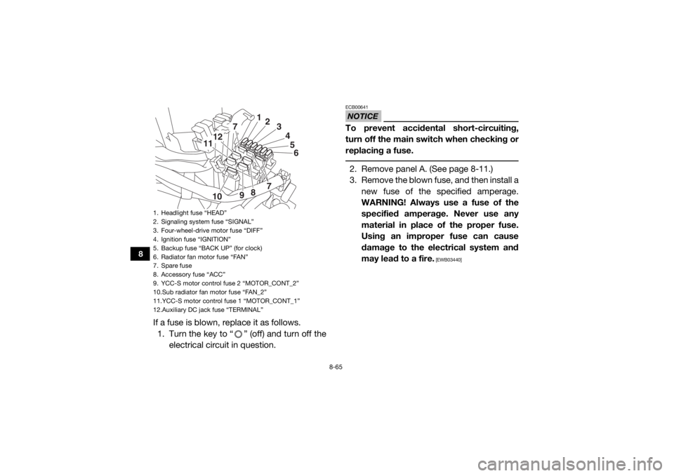
If a fuse is blown, replace it as follows.1. Turn the key to “ ” (off) and turn off the electrical circuit in question.
NOTICEECB00641To prevent accidental short-circuiting,
turn off the main switch when checking or
replacing a fuse. 2. Remove panel A. (See page 8-11.)
3. Remove the blown fuse, and then install anew fuse of the specified amperage.
WARNING! Always use a fuse of the
specified amperage. Never use any
material in place of the proper fuse.
Using an improper fuse can cause
damage to the electrical system and
may lead to a fire.
[EWB03440]
1. Headlight fuse “HEAD”
2. Signaling system fuse “SIGNAL”
3. Four-wheel-drive motor fuse “DIFF”
4. Ignition fuse “IGNITION”
5. Backup fuse “BACK UP” (for clock)
6. Radiator fan motor fuse “FAN”
7. Spare fuse
8. Accessory fuse “ACC”
9. YCC-S motor control fuse 2 “MOTOR_CONT_2”
10.Sub radiator fan motor fuse “FAN_2”
11.YCC-S motor control fuse 1 “MOTOR_CONT_1”
12.Auxiliary DC jack fuse “TERMINAL”
56
7
7
12
11
10 98 4
3
2
1
UB5H7AE0.book Page 65 Wednesday, July 4, 2018 1:37 PM