diagram YAMAHA YZ125LC 2001 User Guide
[x] Cancel search | Manufacturer: YAMAHA, Model Year: 2001, Model line: YZ125LC, Model: YAMAHA YZ125LC 2001Pages: 558, PDF Size: 13.11 MB
Page 120 of 558

2-15
SPECCABLE ROUTING DIAGRAM
AInstall the brake hose so that its pipe portion
directs as show and lightly touches the
projection on the master cylinder.
BPass the “ENGINE STOP” button lead in
the middle of the clutch holder.
CPass the clutch cable in front of the throttle
cable.
DClamp the “ENGINE STOP” button lead to
the handlebar to 3 clicks.
EPass the brake hose in front of the number
plate and through the cable guide.
FCross the clutch cable and throttle cable
over the number plate boss. 1Brake hose
2Master cylinder
3“ENGINE STOP” button lead
4“ENGINE STOP” button
5Throttle cable
6Clutch cable
7Clamp
8Cable guide
5MV-9-30-2B 6/19/00 1:14 PM Page 30
Page 121 of 558

2-15
SPEC
SCHEMA DE CHEMINEMENT DES CABLES
KABELFÜHRUNGSÜBERSICHTPLAN
DIAGRAMMA DEL PASSAGGIO DEI CAVI
1Bremsschlauch
2Hauptbremszylinder
3Leitungskabel des Motorstoppknopfes
„ENGINE STOP“
4Motorstoppknopf „ENGINE STOP“
5Gasseil
6Kupplungskabel
7Klemme
8Kabelführung
ADen Bremsschlauch so einbauen, daß
sein Rohrteil gemäß Abbildung ange-
ordnet ist und den Überstand am
Hauptbremszylinder leicht berührt.
BDas Leitungskabel des Motorstopp-
knopfes „ENGINE STOP“ in der Mitte
des Kupplungshalters durchführen.
CDas Kupplungsseil vor dem Gasseil
durchführen.
DKabel des Motorausschaltknopfes am
Lenker festklemmen mit 3 klicks.
EDen Bremsschlauch vor dem Num-
mernschild und durch die Kabelführung
durchführen.
FDas Kupplungsseil und das Gasseil
über der Nummernschild-Befesti-
gungsnabe überkreuzen.1Tuyau de frein
2Maître-cylindre
3Fil de bouton d’arrêt du moteur “ENGI-
NE STOP”
4Bouton d’arrêt du moteur “ENGINE
STOP”
5Câble d’accélérateur
6Câble d’embrayage
7Bride
8Guide de câble
ŒIstaller la tuyau de frein de manière que
la partie avec le tuyau soit dirigée
comme indipué et touche légèrement la
saillie sur le maîtrecylindre.
ºFaire passer le fil de bouton d’arrêt du
moteur “ENGINE STOP” au centre du
support d’embrayage.
Faire passer le câble d’embrayage devant
le câble d’accélérateur.
¶Fixer le fil du bouton “ENGINE STOP”
sur le guidon (3 déclics).
«Faire passer le tuyau de frein devant la
plaque d’immatriculation et à travers le
guide de câble.
ÄCroiser le câble d’embrayage et le câble
d’accélérateur sur le bossage de fixation
de la plaque minéralogique.1Tubo flessibile del freno
2Cilindro principale
3Conduttore del pulsante “ARRESTO
MOTORE”
4Pulsante “ARRESTO MOTORE”
5Cavo dell’acceleratore
6Cavo della frizione
7Nastro
8Guida per cavi
ŒInstallare il tubo flessibile del freno in
modo che la sua parte di tubo sia rivolta
come illustrato e tocchi leggermente la
sporgenza sul cilindro principale.
ºFar passare il conduttore del pulsante
“ARRESTO MOTORE” nel mezzo del
supporto della frizione.
Far passare il cavo della frizione davanti
al cavo dell’acceleratore.
¶Bloccare il conduttore del pulsante
“ARRESTO MOTORE” sul manubrio
dopo 3 scatti.
«Far passare il tubo flessibile del freno
davanti alla targa e attraverso la guida
per cavi.
ÄIncrociare il cavo della frizione e il cavo
dell’acceleratore sopra il mozzo della
targa.
5MV-9-30-2B 6/19/00 1:14 PM Page 31
Page 220 of 558

4-6
ENGRADIATOR
EC455000
ASSEMBLY AND INSTALLATION
EC445341
Radiator
1. Install:
9Radiator breather hose 1
9Radiator hose 3 2
9Radiator hose 1 3
To radiator (right) 4.
NOTE:
Install the radiator hose 3 with its shorter pro-
truding length afrom the protector 5on the ra-
diator side.
2. Install:
9Radiator (right) 1
9Bolt [radiator (right)] 2
9Radiator hose 4 3
Refer to “CABLE ROUTING DIAGRAM”
section in the CHAPTER 2.
3. Install:
9Radiator (left) 1
9Bolt [radiator (left)] 2
9Radiator hose 2 3
Refer to “CABLE ROUTING DIAGRAM”
section in the CHAPTER 2.
4. Tighten:
9Clamp (radiator hose 1, 3) 4
5. Install:
9Panel 1
NOTE:
9Take care not to bend the panel more than nec-
essary.
9Hook the panel first on the inner side aand
then on the outer side.
1 Nm (0.1 m•kg, 0.7 ft•lb)
1 Nm (0.1 m•kg, 0.7 ft•lb)
1 Nm (0.1 m•kg, 0.7 ft•lb)
1 Nm (0.1 m•kg, 0.7 ft•lb)
1 Nm (0.1 m•kg, 0.7 ft•lb)
5MV-9-30-4A 6/19/00 1:47 PM Page 12
Page 240 of 558

4-16
ENGCARBURETOR AND REED VALVE
2. Tighten:
9Screw (air filter joint) 1
9Screw (carburetor joint) 2
3. Clamp:
9Air vent hose 1
9Overflow hose 2
Refer to “CABLE ROUTING DIAGRAM”
section in the CHAPTER 2.
4. Adjust:
9Idle speed
Refer to “IDLE SPEED ADJUSTMENT”
section in the CHAPTER 3.
5MV-9-30-4A 6/19/00 1:47 PM Page 32
Page 320 of 558
![YAMAHA YZ125LC 2001 User Guide 4-56
ENGCDI MAGNETO
7. Connect:
9CDI magneto lead 1
Refer to “CABLE ROUTING DIAGRAM”
section in the CHAPTER 2.
8. Install:
9Gasket [crankcase cover (left)]
9Crankcase cover (left) 1
9Screw [crankc](/img/51/53921/w960_53921-319.png "YAMAHA YZ125LC 2001 User Guide 4-56
ENGCDI MAGNETO
7. Connect:
9CDI magneto lead 1
Refer to “CABLE ROUTING DIAGRAM”
section in the CHAPTER 2.
8. Install:
9Gasket [crankcase cover (left)]
9Crankcase cover (left) 1
9Screw [crankc")
4-56
ENGCDI MAGNETO
7. Connect:
9CDI magneto lead 1
Refer to “CABLE ROUTING DIAGRAM”
section in the CHAPTER 2.
8. Install:
9Gasket [crankcase cover (left)]
9Crankcase cover (left) 1
9Screw [crankcase cover (left)] 2
NOTE:
Tighten the screws in stage, using a crisscross
pattern.
5 Nm (0.5 m•kg, 3.6 ft•lb)
5MV-9-30-4C 6/19/00 1:42 PM Page 38
Page 484 of 558
6-1
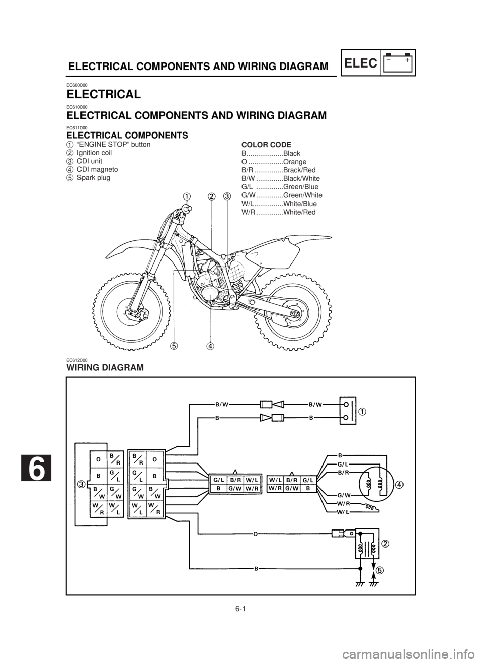
ELECELECTRICAL COMPONENTS AND WIRING DIAGRAM
EC600000
ELECTRICAL
EC610000
ELECTRICAL COMPONENTS AND WIRING DIAGRAM
EC611000
ELECTRICAL COMPONENTS
1“ENGINE STOP” button
2Ignition coil
3CDI unit
4CDI magneto
5Spark plug
EC612000
WIRING DIAGRAM
COLOR CODE
B...................Black
O ..................Orange
B/R ...............Brack/Red
B/W ..............Black/White
G/L ..............Green/Blue
G/W ..............Green/White
W/L...............White/Blue
W/R ..............White/Red
6
5MV-9-30-6 6/19/00 1:25 PM Page 2