clutch YAMAHA YZ125LC 2001 Owner's Manual
[x] Cancel search | Manufacturer: YAMAHA, Model Year: 2001, Model line: YZ125LC, Model: YAMAHA YZ125LC 2001Pages: 558, PDF Size: 13.11 MB
Page 276 of 558
![YAMAHA YZ125LC 2001 Owners Manual 4-34
ENGCLUTCH AND PRIMARY DRIVEN GEAR
EC495000
ASSEMBLY AND INSTALLATION
EC495240
Clutch
1. Install:
9Plain washer [φ34 mm (1.34 in)] 1
9Spacer 2
9Bearing 3
9Primary driven gear 4
NOTE:
Apply the tr](/img/51/53921/w960_53921-275.png "YAMAHA YZ125LC 2001 Owners Manual 4-34
ENGCLUTCH AND PRIMARY DRIVEN GEAR
EC495000
ASSEMBLY AND INSTALLATION
EC495240
Clutch
1. Install:
9Plain washer [φ34 mm (1.34 in)] 1
9Spacer 2
9Bearing 3
9Primary driven gear 4
NOTE:
Apply the tr")
4-34
ENGCLUTCH AND PRIMARY DRIVEN GEAR
EC495000
ASSEMBLY AND INSTALLATION
EC495240
Clutch
1. Install:
9Plain washer [φ34 mm (1.34 in)] 1
9Spacer 2
9Bearing 3
9Primary driven gear 4
NOTE:
Apply the transmission oil on the spacer, bearing
and primary driven gear inner circumference.
2. Install:
9Plain washer [φ34 mm (1.34 in)] 1
9Clutch boss 2
3. Install:
9Lock washer 1
9Nut (clutch boss) 2
NOTE:
Use the clutch holding tool 3, 4to hold the
clutch boss.
å
For USA and CDN
∫
Except for USA and CDN
4. Bend the lock washer 1tab.
80 Nm (8.0 m•kg, 58 ft•lb)
Clutch holding tool:
YM-91042...............................3 3
90890-04086...........................4 4
å
∫
5MV-9-30-4B 1/7/04 5:29 PM Page 34
Page 278 of 558

4-35
ENGCLUTCH AND PRIMARY DRIVEN GEAR
5. Install:
9Friction plate 1 1
9Clutch plate 2
9Friction plate 2 3
NOTE:
9Install the clutch plates and friction plates alter-
nately on the clutch boss, starting with a friction
plate and ending with a friction plate.
9Use the friction plates 1 for the first and final
while paying attention to the difference in sur-
face pattern.
9Apply the transmission oil on the friction plates
and clutch plates.
10 Nm (1.0 m•kg, 7.2 ft•lb)
8. Install:
9Clutch spring 1
9Screw (clutch spring) 2
NOTE:
Tighten the screws in stage, using a crisscross
pattern.
6. Install:
9Push rod 1
9Plain washer 2
9Bearing 3
To pressure plate 4.
NOTE:
Apply the lithium soap base grease on the bear-
ing, plain washer and push rod.
7. Install:
9Pressure plate 1
5MV-9-30-4B 6/19/00 1:45 PM Page 36
Page 280 of 558

4-36
ENGCLUTCH AND PRIMARY DRIVEN GEAR
EC495121
Push lever
1. Install:
9Torsion spring 1
9Push lever 2
To push lever axle 3.
NOTE:
9Install the push lever with its 5mark adown-
ward.
9Temporarily install the torsion spring and push
lever at this point.
2. Check:
9Push lever position
NOTE:
When pushing the push lever forward, the front
line bshould be within the range a. If not, rein-
stall the push lever.
3. Adjust:
9Push lever position 10. Install:
9Clutch cover 1
9Bolt (clutch cover) 2
NOTE:
Tighten the bolts in stage, using a crisscross
pattern.
10 Nm (1.0 m•kg, 7.2 ft•lb)
Adjustment steps:
9Remove the push lever 1from the push
lever axle 2.
9Re-install the push lever so that the projec-
tion is positioned between alignment marks
when pushing the push lever forward.
9. Install:
9Gasket (clutch cover) 1
NOTE:
Position the rack aon the push rod backward.
5MV-9-30-4B 6/19/00 1:45 PM Page 38
Page 282 of 558

4-37
ENGCLUTCH AND PRIMARY DRIVEN GEAR
4. Install:
9Plain washer 1
9Circlip 2
5MV-9-30-4B 6/19/00 1:45 PM Page 40
Page 284 of 558

4-38
ENG
KICK AXLE, SHIFT SHAFT AND PRIMARY DRIVE
GEAR
Extent of removal Order Part name Q’ty Remarks
RPIMARY DRIVE GEAR REMOVAL
Preparation for Drain the transmission oil.Refer to “TRANSMISSION OIL REPLACE-
removalMENT“ section in the CHAPTER 3.
Clutch cable Disconnect at engine side.
Bolt (brake pedal) Shift the brake pedal downward.
Radiator hose 4 Disconnect at water pump side.
Bolt (push rod)
Refer to “CYLINDER HEAD, CYLINDER
AND PISTON” section.
1 Kick starter 1
2 Crankcase cover (right) 1
3 Bolt (Primary drive gear) 1 Only loosening
Refer to “REMOVAL POINTS”.
4 Primary driven gear 1 Refer to “CLUTCH AND PRIMARY
DRIVEN GEAR”section.
5 Primary drive gear 1
EC4C0000
KICK AXLE, SHIFT SHAFT AND PRIMARY DRIVE GEAREC4C8000PRIMARY DRIVE GEAR
1
Extent of removal:1Primary drive gear removal
10 Nm (1.0 m•kg, 7.2 ft•lb)
10 Nm (1.0 m•kg, 7.2 ft•lb)
55 Nm (5.5 m•kg, 40 ft•lb)
5MV-9-30-4C 6/19/00 1:41 PM Page 2
Page 296 of 558

4-44
ENG
KICK AXLE, SHIFT SHAFT AND PRIMARY DRIVE
GEAR
4. Hook:
9Torsion spring 1
NOTE:
Turn the torsion spring clockwise and hook into
the proper hole ain the crankcase.
EC4C5402
Kick idle gear
1. Install:
9Circlip 1
9Kick idle gear 2
9Plain washer 3
NOTE:
9Apply the transmission oil on the kick idle gear
inner circumference.
9Install the kick idle gear with its depressed side
atoward you.
EC4C5502
Primary drive gear
1. Install:
9Primary drive gear 1
9Bolt 2
NOTE:
Temporarily tighten the bolt at this point.
2. Install:
9Primary driven gear
Refer to “CLUTCH AND PRIMARY DRI-
VEN GEAR” section.
3. Tighten:
9Bolt (primary drive gear) 1
NOTE:
Place an aluminum plate abetween the teeth of
the primary drive gear 2and driven gear 3.
4. Install:
9Dowel pin 1
9Gasket [crankcase cover (right)] 2
55 Nm (5.5 m•kg, 40 ft•lb)
5MV-9-30-4C 6/19/00 1:41 PM Page 14
Page 298 of 558

4-45
ENG
KICK AXLE, SHIFT SHAFT AND PRIMARY DRIVE
GEAR
5. Install:
9Crankcase cover (right) 1
NOTE:
9Position the rack aon the push rod backward.
9Mesh the governor gear 2, and impeller shaft
gear 3with primary drive gear 4.
6. Install:
9Bolt [crankcase cover (right)] 1
NOTE:
Tighten the bolts in stage, using a crisscross
pattern.
7. Install:
9Kick starter 1
9Plain washer 2
9Bolt (kick starter) 3
NOTE:
Install the kick starter closest to but not contact-
ing the pillar tube 4.
8. Install:
9Shift pedal 1
9Bolt (shift pedal) 2
NOTE:
Install the shift pedal so that the top of the shift
pedal outer diameter ais highest without ex-
ceeding the line bconnecting the center of the
shift shaft and screw [crankcase cover (left)] 3.
9. Check:
9Push lever position
Refer to “CLUTCH AND PRIMARY DRI-
VEN GEAR” section.
10 Nm (1.0 m•kg, 7.2 ft•lb)
10 Nm (1.0 m•kg, 7.2 ft•lb)
10 Nm (1.0 m•kg, 7.2 ft•lb)
5MV-9-30-4C 6/19/00 1:41 PM Page 16
Page 322 of 558

4-57
ENGENGINE REMOVAL
Extent of removal Order Part name Q’ty Remarks
ENGINE REMOVAL
Preparation for
Hold the machine by placing the
removalsuitable stand under the engine.
Seat and fuel tankRefer to “SEAT, FUEL TANK AND
SIDE COVERS” section.
Carburetor Refer to “CARBURETOR AND REED
VALVE” section.
Exhaust pipe and silencer Refer to “EXHAUST PIPE AND
SILENCER” section.
Clutch cable Disconnect at engine side.
Radiator hose 2 Disconnect at cylinder head side.
Radiator hose 4 Disconnect at water pump side.
Bolt (radiator) Refer to “RADIATOR” section.
Radiator hose 3 Disconnect at right side radiator,
then shift the radiators forward.
Spark plug cap
Disconnect the CDI magneto lead.
EC4M0000
w
Support the machine securely so there is no dan-
ger of it falling over.
26 Nm (2.6 m•kg, 19 ft•lb)
34 Nm (3.4 m•kg, 24 ft•lb)
69 Nm (6.9 m•kg, 50 ft•lb)
69 Nm (6.9 m•kg, 50 ft•lb)
85 Nm (8.5 m•kg, 61 ft•lb)
60 Nm (6.0 m•kg, 43 ft•lb)
5 Nm (0.5 m•kg, 3.6 ft•lb)
5MV-9-30-4D 6/19/00 1:39 PM Page 2
Page 434 of 558
5-40
CHASHANDLEBAR
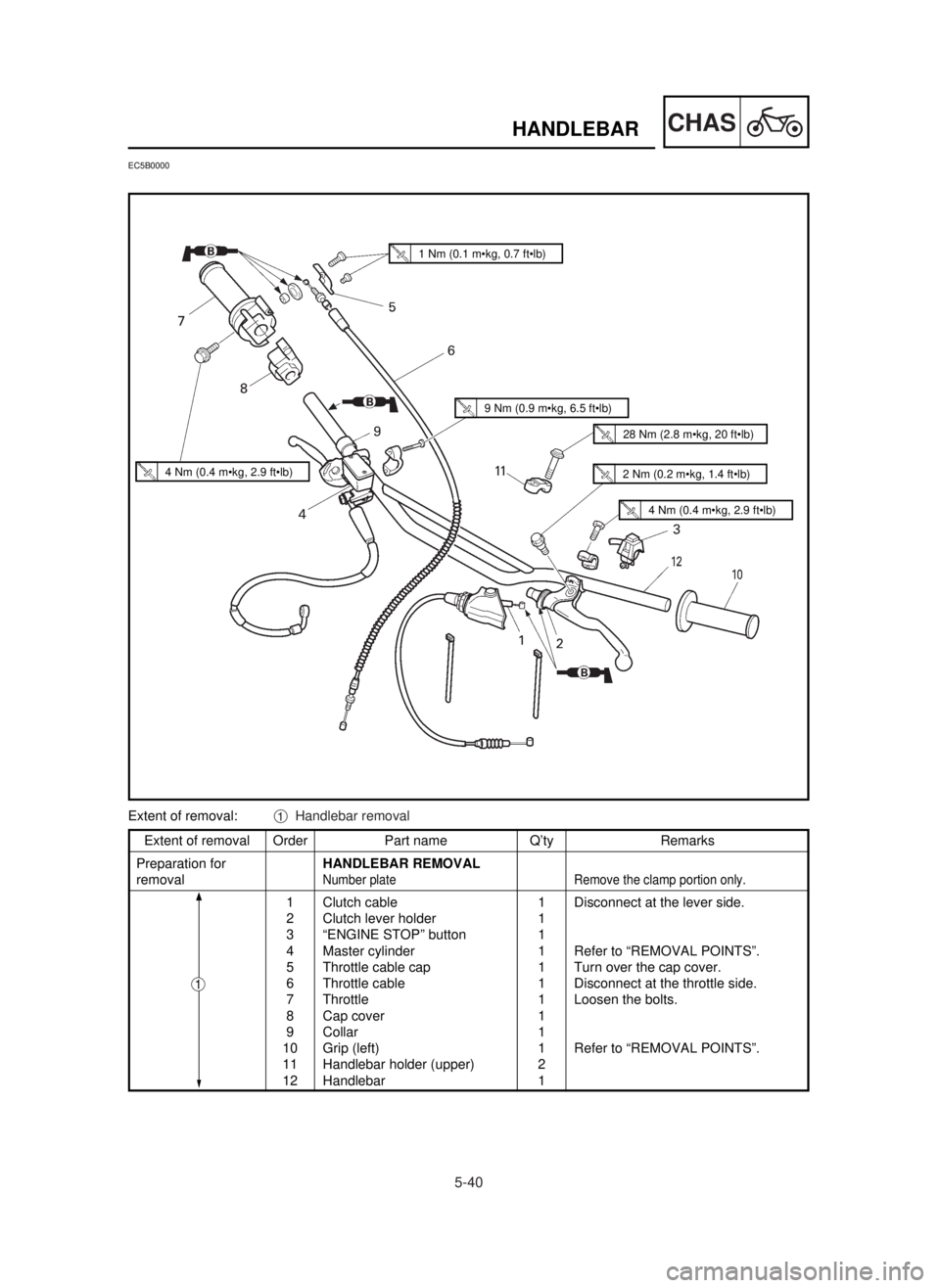
Extent of removal Order Part name Q’ty Remarks
Preparation forHANDLEBAR REMOVAL
removal
Number plate Remove the clamp portion only.
1 Clutch cable 1 Disconnect at the lever side.
2 Clutch lever holder 1
3 “ENGINE STOP” button 1
4 Master cylinder 1 Refer to “REMOVAL POINTS”.
5 Throttle cable cap 1 Turn over the cap cover.
6 Throttle cable 1 Disconnect at the throttle side.
7 Throttle 1 Loosen the bolts.
8 Cap cover 1
9 Collar 1
10 Grip (left) 1 Refer to “REMOVAL POINTS”.
11 Handlebar holder (upper) 2
12 Handlebar 1
EC5B0000
1
Extent of removal:1Handlebar removal
1 Nm (0.1 m•kg, 0.7 ft•lb)
4 Nm (0.4 m•kg, 2.9 ft•lb)
9 Nm (0.9 m•kg, 6.5 ft•lb)
28 Nm (2.8 m•kg, 20 ft•lb)
4 Nm (0.4 m•kg, 2.9 ft•lb)
2 Nm (0.2 m•kg, 1.4 ft•lb)
5MV-9-30-5C 6/19/00 1:27 PM Page 2
Page 444 of 558
5-45
CHASHANDLEBAR
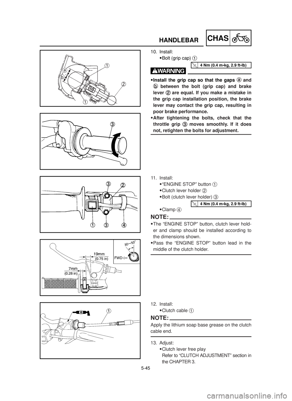
10. Install:
9Bolt (grip cap) 1
w
9Install the grip cap so that the gaps a a
and
b b
between the bolt (grip cap) and brake
lever 2 2
are equal. If you make a mistake in
the grip cap installation position, the brake
lever may contact the grip cap, resulting in
poor brake performance.
9After tightening the bolts, check that the
throttle grip 3 3
moves smoothly. If it does
not, retighten the bolts for adjustment.
11. Install:
9“ENGINE STOP” button 1
9Clutch lever holder 2
9Bolt (clutch lever holder) 3
9Clamp 4
NOTE:
9The “ENGINE STOP” button, clutch lever hold-
er and clamp should be installed according to
the dimensions shown.
9Pass the “ENGINE STOP” button lead in the
middle of the clutch holder.
12. Install:
9Clutch cable 1
NOTE:
Apply the lithium soap base grease on the clutch
cable end.
13. Adjust:
9Clutch lever free play
Refer to “CLUTCH ADJUSTMENT” section in
the CHAPTER 3.
4 Nm (0.4 m•kg, 2.9 ft•lb)
4 Nm (0.4 m•kg, 2.9 ft•lb)
5MV-9-30-5C 6/19/00 1:27 PM Page 12