transmission oil YAMAHA YZ125LC 2001 Owner's Manual
[x] Cancel search | Manufacturer: YAMAHA, Model Year: 2001, Model line: YZ125LC, Model: YAMAHA YZ125LC 2001Pages: 558, PDF Size: 13.11 MB
Page 296 of 558

4-44
ENG
KICK AXLE, SHIFT SHAFT AND PRIMARY DRIVE
GEAR
4. Hook:
9Torsion spring 1
NOTE:
Turn the torsion spring clockwise and hook into
the proper hole ain the crankcase.
EC4C5402
Kick idle gear
1. Install:
9Circlip 1
9Kick idle gear 2
9Plain washer 3
NOTE:
9Apply the transmission oil on the kick idle gear
inner circumference.
9Install the kick idle gear with its depressed side
atoward you.
EC4C5502
Primary drive gear
1. Install:
9Primary drive gear 1
9Bolt 2
NOTE:
Temporarily tighten the bolt at this point.
2. Install:
9Primary driven gear
Refer to “CLUTCH AND PRIMARY DRI-
VEN GEAR” section.
3. Tighten:
9Bolt (primary drive gear) 1
NOTE:
Place an aluminum plate abetween the teeth of
the primary drive gear 2and driven gear 3.
4. Install:
9Dowel pin 1
9Gasket [crankcase cover (right)] 2
55 Nm (5.5 m•kg, 40 ft•lb)
5MV-9-30-4C 6/19/00 1:41 PM Page 14
Page 304 of 558

4-48
ENGYPVS GOVERNOR
2. Install:
9Ball 1
9Retainer 2
To governor shaft 3.
NOTE:
Apply the transmission oil on the retainer and
ball.
3. Install:
9Dowel pin 1
NOTE:
9While compressing the spring, install the dowel
pin.
9Make sure the dowel pin fits into the groove a
in the retainer.
4. Install:
9Governor assembly 1
NOTE:
Align the groove ain the governor with the fork
band set the governor in the crankcase cover.
5MV-9-30-4C 6/19/00 1:42 PM Page 22
Page 308 of 558

4-50
ENGWATER PUMP
EC4G3000
REMOVAL POINTS
EC4G3110
Impeller shaft
1. Remove:
9Impeller 1
9Plain washer 2
9Impeller shaft 3
NOTE:
Hold the impeller shaft on its width across the
flats awith spanners, etc. and remove the im-
peller.
EC4G3210
Oil seal
NOTE:
It is not necessary to disassemble the water
pump, unless there is an abnormality such as
excessive change in coolant level, discoloration
of coolant, or milky transmission oil.
1. Remove:
9Bearing 1
2. Remove:
9Oil seal 1
EC4G4000
INSPECTIONEC444200
Impeller shaft
1. Inspect:
9Impeller shaft 1
Bend/Wear/Damage ÕReplace.
Fur deposits ÕClean.
5MV-9-30-4C 6/19/00 1:42 PM Page 26
Page 344 of 558

4-68
ENGCRANKCASE AND CRANKSHAFT
6. Install:
9Holder 1
9Bolt (holder) 2
7. Install:
9Segment 1
9Bolt (segment) 2
NOTE:
9When installing the segment onto the shift cam
3, align the punch mark awith the dowel pin
b.
9Turn the segment clockwise until it stops and
tighten the bolt.
8. Remove:
9Sealant
Forced out on the cylinder mating surface.
9. Apply:
9Engine oil
To the crank pin, bearing, oil delivery hole
and connecting rod big end washer.
10. Check:
9Crankshaft and transmission operation
Unsmooth operation ÕRepair.
30 Nm (3.0 m•kg, 22 ft•lb)
10 Nm (1.0 m•kg, 7.2 ft•lb)
5MV-9-30-4D 6/19/00 1:39 PM Page 24
Page 350 of 558

4-71
ENGTRANSMISSION, SHIFT CAM AND SHIFT FORK
EC4H4801
Shift fork, shift cam and segment
1. Inspect:
9Shift fork 1
Wear/Damage/Scratches ÕReplace.
2. Inspect:
9Shift cam 1
9Segment 2
9Guide bar 3
Bend/Wear/Damage ÕReplace.
3. Check:
9Shift fork movement
On its guide bar.
Unsmooth operation ÕReplace shift fork
and/or guide bar.
NOTE:
For a malfunctioning shift fork, replace not only
the shift fork itself but the two gears each adja-
cent to the shift fork.
EC4H5000
ASSEMBLY AND INSTALLATION
EC4H5202
Transmission
1. Install:
95th pinion gear (23T) 1
93rd/4th pinion gear (17T/21T) 2
96th pinion gear (24T) 3
92nd pinion gear (15T) 4
To main axle 5.
NOTE:
9Apply the molybdenum disulfide oil on the 5th
and 6th pinion gears inner circumference.
9Apply the transmission oil on the 2nd and
3rd/4th pinion gears inner circumference.
5MV-9-30-4D 6/19/00 1:39 PM Page 30
Page 352 of 558

4-72
ENGTRANSMISSION, SHIFT CAM AND SHIFT FORK
2. Install:
92nd wheel gear (28T) 1
96th wheel gear (24T) 2
94th wheel gear (27T) 3
93rd wheel gear (26T) 4
95th wheel gear (26T) 5
91st wheel gear (30T) 6
To drive axle 7.
NOTE:
9Apply the molybdenum disulfide oil on the 1st,
2nd, 3rd and 4th wheel gears inner circumfer-
ence.
9Apply the transmission oil on the 5th and 6th
wheel gears inner circumference.
3. Install:
9Plain washer 1
9Circlip 2
NOTE:
9Be sure the circlip sharp-edged corner ais po-
sitioned opposite side to the plain washer and
gear b.
9Be sure the circlip end cis positioned at axle
spline groove d.
4. Install:
9Main axle 1
9Drive axle 2
NOTE:
9Apply the lithium soap base grease on the
crankcase oil seal lip.
9When installing the drive axle into the
crankcase, pay careful attention to the
crankcase oil seal lip.
5MV-9-30-4D 6/19/00 1:39 PM Page 32
Page 354 of 558

4-73
ENGTRANSMISSION, SHIFT CAM AND SHIFT FORK
EC4H5331
Shift cam and shift fork
1. Install:
9Shift fork 1 (L) 1
9Shift fork 2 2
9Shift fork 3 (R) 3
NOTE:
9Mesh the shift fork #1 (L) with the 6th wheel
gear 4and #3 (R) with the 5th wheel gear 6
on the drive axle.
9Mesh the shift fork #2 with the 3rd/4th pinion
gear 5on the main axle.
2. Install:
9Shift cam 1
NOTE:
Apply the transmission oil on the shift cam.
3. Install:
9Guide bar (short) 1
9Guide bar (long) 2
NOTE:
9Apply the transmission oil on the guide bars.
9Be sure the long bar is inserted into the shift
forks #1 and #3 and the short one into #2.
4. Check:
9Shifter operation
9Transmission operation
Unsmooth operation ÕRepair.
5MV-9-30-4D 6/19/00 1:39 PM Page 34
Page 361 of 558
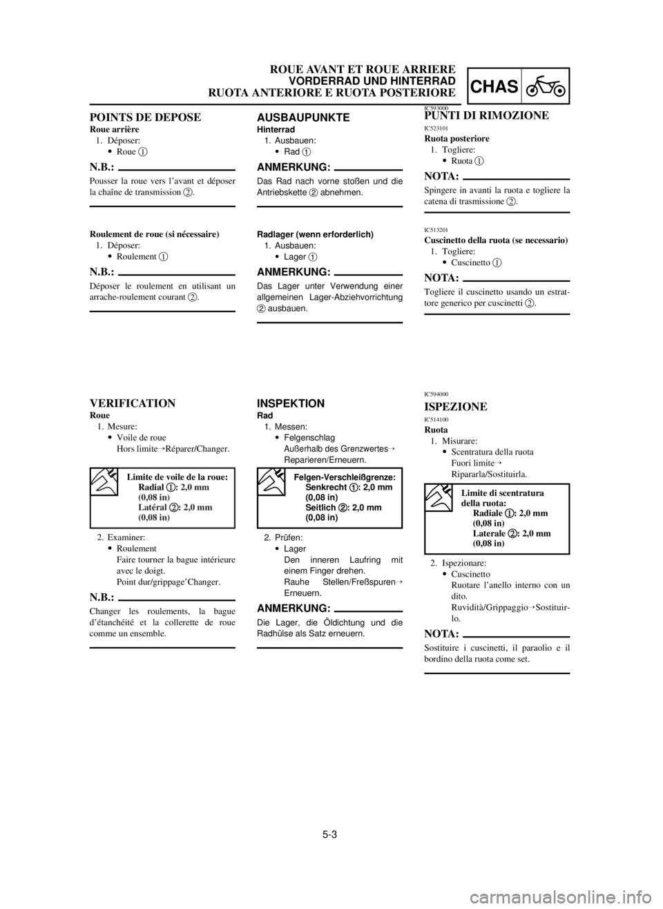
5-3
CHAS
ROUE AVANT ET ROUE ARRIERE
VORDERRAD UND HINTERRAD
RUOTA ANTERIORE E RUOTA POSTERIORE
AUSBAUPUNKTE
Hinterrad
1. Ausbauen:
9Rad 1
ANMERKUNG:
Das Rad nach vorne stoßen und die
Antriebskette 2abnehmen.
Radlager (wenn erforderlich)
1. Ausbauen:
9Lager 1
ANMERKUNG:
Das Lager unter Verwendung einer
allgemeinen Lager-Abziehvorrichtung
2ausbauen.
INSPEKTION
Rad
1. Messen:
9Felgenschlag
Außerhalb des GrenzwertesÕ
Reparieren/Erneuern.
2. Prüfen:
9Lager
Den inneren Laufring mit
einem Finger drehen.
Rauhe Stellen/FreßspurenÕ
Erneuern.
ANMERKUNG:
Die Lager, die Öldichtung und die
Radhülse als Satz erneuern.
POINTS DE DEPOSE
Roue arrière
1. Déposer:
9Roue 1
N.B.:
Pousser la roue vers l’avant et déposer
la chaîne de transmission 2.
Roulement de roue (si nécessaire)
1. Déposer:
9Roulement 1
N.B.:
Déposer le roulement en utilisant un
arrache-roulement courant 2.
VERIFICATION
Roue
1. Mesure:
9Voile de roue
Hors limiteÕRéparer/Changer.
2. Examiner:
9Roulement
Faire tourner la bague intérieure
avec le doigt.
Point dur/grippage’Changer.
N.B.:
Changer les roulements, la bague
d’étanchéité et la collerette de roue
comme un ensemble.
IC593000PUNTI DI RIMOZIONE
IC523101
Ruota posteriore
1. Togliere:
9Ruota 1
NOTA:
Spingere in avanti la ruota e togliere la
catena di trasmissione 2.
IC513201
Cuscinetto della ruota (se necessario)
1. Togliere:
9Cuscinetto 1
NOTA:
Togliere il cuscinetto usando un estrat-
tore generico per cuscinetti 2.
IC594000
ISPEZIONE
IC514100
Ruota
1. Misurare:
9Scentratura della ruota
Fuori limiteÕ
Ripararla/Sostituirla.
2. Ispezionare:
9Cuscinetto
Ruotare l’anello interno con un
dito.
Ruvidità/Grippaggio
ÕSostituir-
lo.
NOTA:
Sostituire i cuscinetti, il paraolio e il
bordino della ruota come set.
Limite de voile de la roue:
Radial 1 1
: 2,0 mm
(0,08 in)
Latéral 2 2
: 2,0 mm
(0,08 in)
Limite di scentratura
della ruota:
Radiale 1 1
: 2,0 mm
(0,08 in)
Laterale 2 2
: 2,0 mm
(0,08 in)
Felgen-Verschleißgrenze:Senkrecht 1 1
: 2,0 mm
(0,08 in)
Seitlich 2 2
: 2,0 mm
(0,08 in)
5MV-9-30-5A 6/19/00 1:35 PM Page 7