remove YAMAHA YZ250F 2001 Betriebsanleitungen (in German)
[x] Cancel search | Manufacturer: YAMAHA, Model Year: 2001, Model line: YZ250F, Model: YAMAHA YZ250F 2001Pages: 656, PDF-Größe: 24.86 MB
Page 248 of 656
3 - 44
INSP
ADJ
STEERING HEAD INSPECTION AND ADJUSTMENT
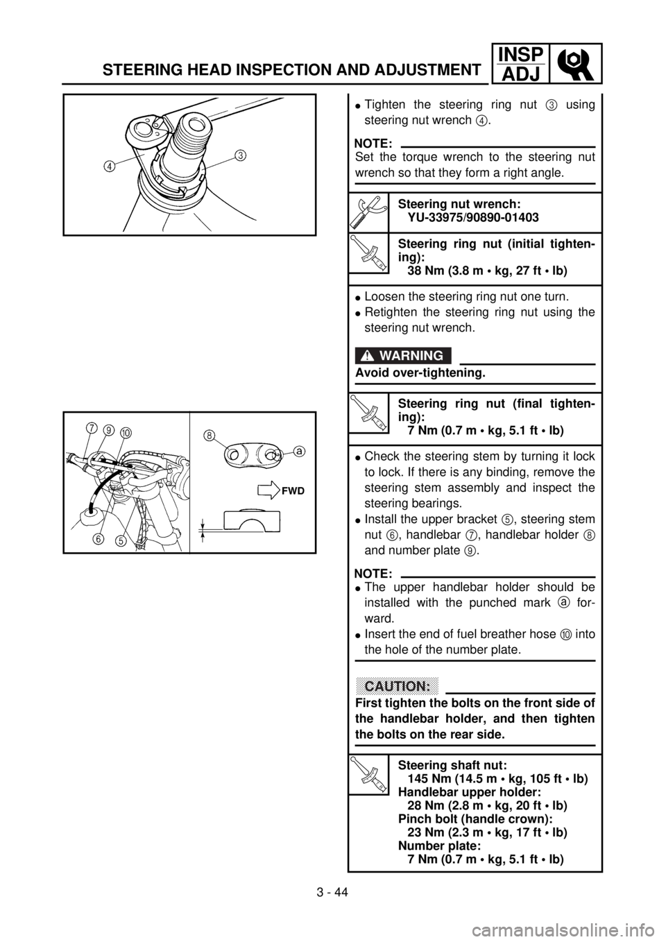
lTighten the steering ring nut 3 using
steering nut wrench 4.
NOTE:
Set the torque wrench to the steering nut
wrench so that they form a right angle.
Steering nut wrench:
YU-33975/90890-01403
T R..
Steering ring nut (initial tighten-
ing):
38 Nm (3.8 m • kg, 27 ft • lb)
lLoosen the steering ring nut one turn.
lRetighten the steering ring nut using the
steering nut wrench.
WARNING
Avoid over-tightening.
T R..
Steering ring nut (final tighten-
ing):
7 Nm (0.7 m • kg, 5.1 ft • lb)
lCheck the steering stem by turning it lock
to lock. If there is any binding, remove the
steering stem assembly and inspect the
steering bearings.
lInstall the upper bracket 5, steering stem
nut 6, handlebar 7, handlebar holder 8
and number plate 9.
NOTE:
lThe upper handlebar holder should be
installed with the punched mark a for-
ward.
lInsert the end of fuel breather hose 0 into
the hole of the number plate.
CAUTION:
First tighten the bolts on the front side of
the handlebar holder, and then tighten
the bolts on the rear side.
T R..
Steering shaft nut:
145 Nm (14.5 m • kg, 105 ft • lb)
Handlebar upper holder:
28 Nm (2.8 m • kg, 20 ft • lb)
Pinch bolt (handle crown):
23 Nm (2.3 m • kg, 17 ft • lb)
Number plate:
7 Nm (0.7 m • kg, 5.1 ft • lb)
Page 252 of 656
3 - 46
INSP
ADJ
ELECTRICAL/SPARK PLUG INSPECTION
EC370000
ELECTRICAL
EC371001
SPARK PLUG INSPECTION
1. Remove:
lSpark plug
2. Inspect:
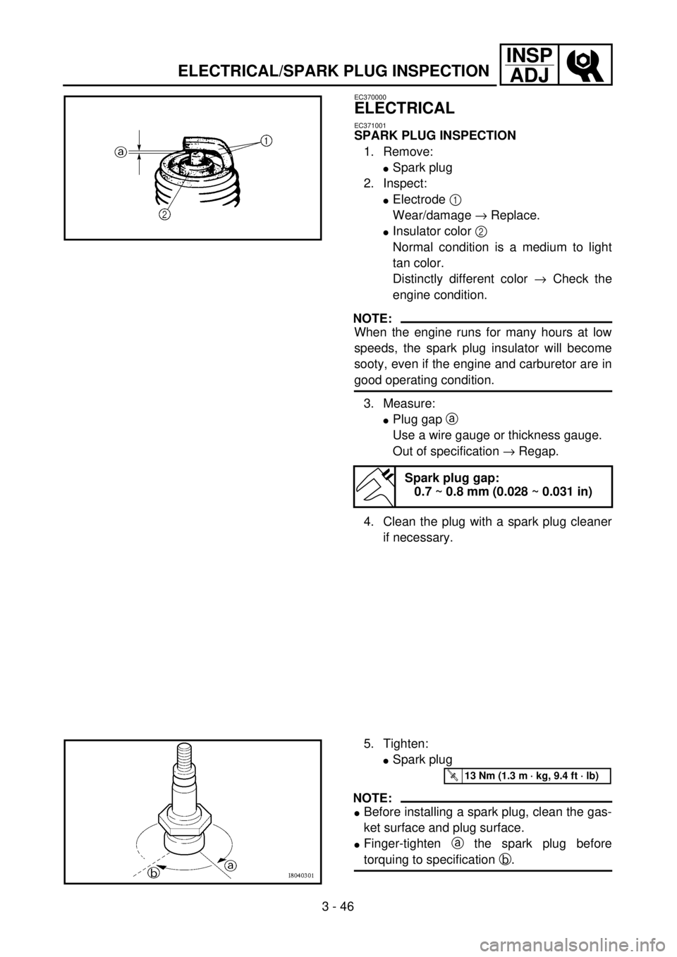
lElectrode 1
Wear/damage ® Replace.
lInsulator color 2
Normal condition is a medium to light
tan color.
Distinctly different color ® Check the
engine condition.
NOTE:
When the engine runs for many hours at low
speeds, the spark plug insulator will become
sooty, even if the engine and carburetor are in
good operating condition.
3. Measure:
lPlug gap a
Use a wire gauge or thickness gauge.
Out of specification ® Regap.
4. Clean the plug with a spark plug cleaner
if necessary.
Spark plug gap:
0.7 ~ 0.8 mm (0.028 ~ 0.031 in)
5. Tighten:
lSpark plug
NOTE:
lBefore installing a spark plug, clean the gas-
ket surface and plug surface.
lFinger-tighten a the spark plug before
torquing to specification b.
T R..13 Nm (1.3 m · kg, 9.4 ft · lb)
Page 254 of 656
3 - 47
INSP
ADJ
IGNITION TIMING CHECK
IGNITION TIMING CHECK
1. Remove:
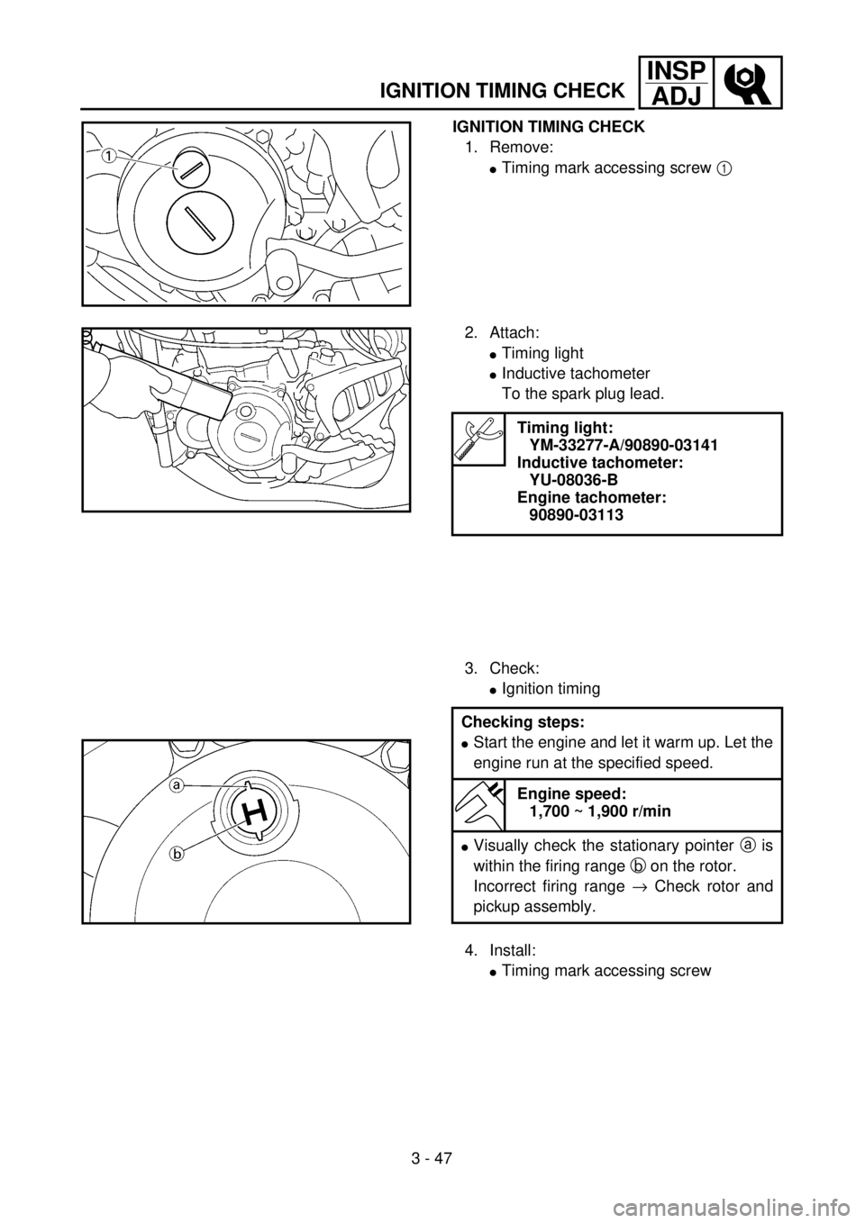
lTiming mark accessing screw 1
2. Attach:
lTiming light
lInductive tachometer
To the spark plug lead.
3. Check:
lIgnition timing
Timing light:
YM-33277-A/90890-03141
Inductive tachometer:
YU-08036-B
Engine tachometer:
90890-03113
Checking steps:
lStart the engine and let it warm up. Let the
engine run at the specified speed.
Engine speed:
1,700 ~ 1,900 r/min
lVisually check the stationary pointer a is
within the firing range b on the rotor.
Incorrect firing range ® Check rotor and
pickup assembly.
4. Install:
lTiming mark accessing screw
Page 256 of 656
4 - 1
ENG
EC400000
ENGINE
SEAT, FUEL TANK AND SIDE COVERS
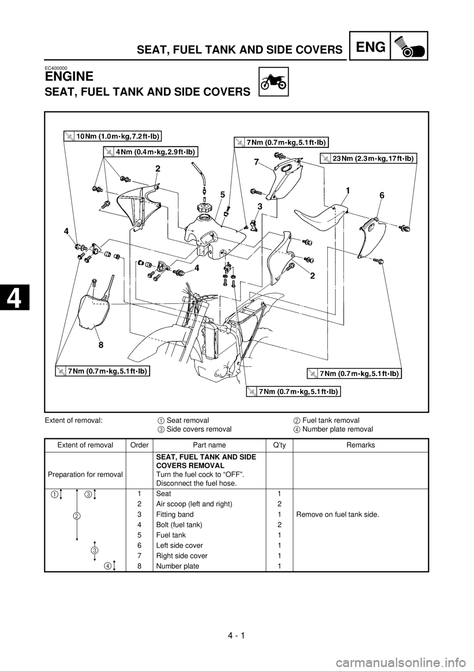
Extent of removal:
1
Seat removal
2
Fuel tank removal
3
Side covers removal
4
Number plate removal
Extent of removal Order Part name Q’ty Remarks
Preparation for removal
SEAT, FUEL TANK AND SIDE
COVERS REMOVAL
Turn the fuel cock to “OFF”.
Disconnect the fuel hose.
1 Seat 1
2 Air scoop (left and right) 2
3 Fitting band 1 Remove on fuel tank side.
4 Bolt (fuel tank) 2
5 Fuel tank 1
6 Left side cover 1
7 Right side cover 1
8 Number plate 1
13
4
2
3
SEAT, FUEL TANK AND SIDE COVERS
4
4
Page 264 of 656
4 - 5
ENG
RADIATOR
EC456000
HANDLING NOTE
WARNING
Do not remove the radiator cap when the
engine and radiator are hot. Scalding hot
fluid and steam may be blown out under
pressure, which could cause serious
injury.
When the engine has cooled, open the radi-
ator cap by the following procedure:
Place a thick rag, like a towel, over the radi-
ator cap, slowly rotate the cap counter-
clockwise to the detent. This procedure
allows any residual pressure to escape.
When the hissing sound has stopped,
press down on the cap while turning coun-
terclockwise and remove it.
EC454000
INSPECTION
EC444100
Radiator
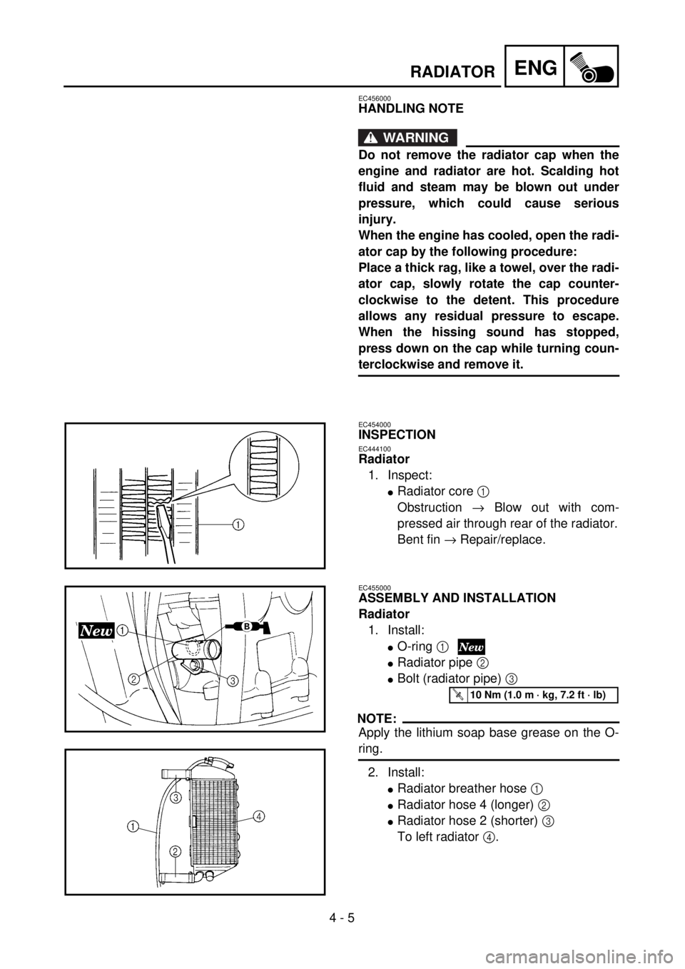
1. Inspect:
l
Radiator core
1
Obstruction
®
Blow out with com-
pressed air through rear of the radiator.
Bent fin
®
Repair/replace.
EC455000
ASSEMBLY AND INSTALLATION
Radiator
1. Install:
l
O-ring
1
l
Radiator pipe
2
l
Bolt (radiator pipe)
3
NOTE:
Apply the lithium soap base grease on the O-
ring.
2. Install:
l
Radiator breather hose
1
lRadiator hose 4 (longer) 2
lRadiator hose 2 (shorter) 3
To left radiator 4.
T R..10 Nm (1.0 m · kg, 7.2 ft · lb)
Page 274 of 656
4 - 10
ENGCARBURETOR
HANDLING NOTE
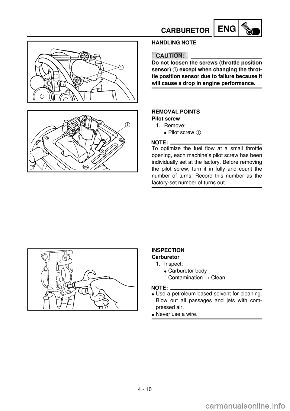
CAUTION:
Do not loosen the screws (throttle position
sensor) 1 except when changing the throt-
tle position sensor due to failure because it
will cause a drop in engine performance.
REMOVAL POINTS
Pilot screw
1. Remove:
lPilot screw 1
NOTE:
To optimize the fuel flow at a small throttle
opening, each machine’s pilot screw has been
individually set at the factory. Before removing
the pilot screw, turn it in fully and count the
number of turns. Record this number as the
factory-set number of turns out.
INSPECTION
Carburetor
1. Inspect:
lCarburetor body
Contamination ® Clean.
NOTE:
lUse a petroleum based solvent for cleaning.
Blow out all passages and jets with com-
pressed air.
lNever use a wire.
Page 296 of 656
4 - 21
ENGCAMSHAFTS
REMOVAL POINTS
Camshaft
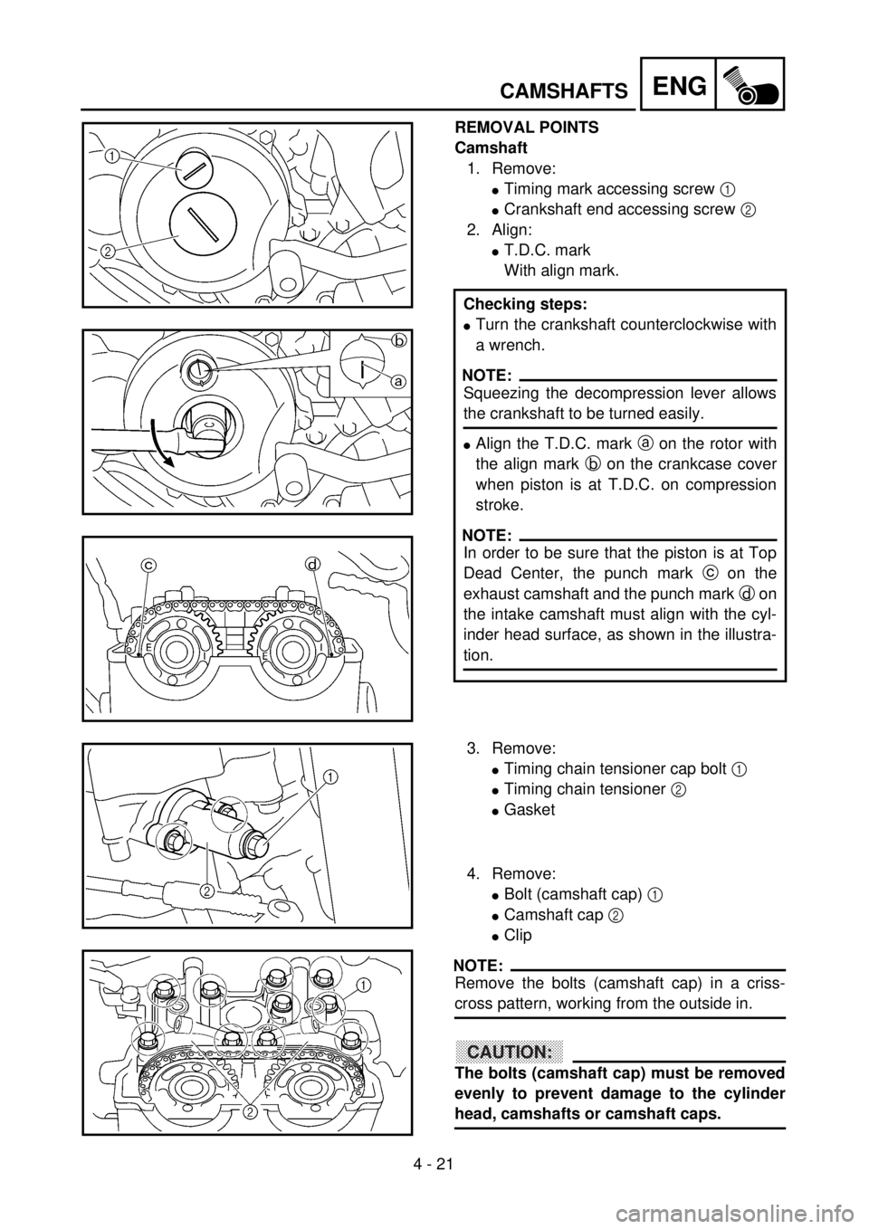
1. Remove:
lTiming mark accessing screw 1
lCrankshaft end accessing screw 2
2. Align:
lT.D.C. mark
With align mark.
Checking steps:
lTurn the crankshaft counterclockwise with
a wrench.
NOTE:
Squeezing the decompression lever allows
the crankshaft to be turned easily.
lAlign the T.D.C. mark a on the rotor with
the align mark b on the crankcase cover
when piston is at T.D.C. on compression
stroke.
NOTE:
In order to be sure that the piston is at Top
Dead Center, the punch mark c on the
exhaust camshaft and the punch mark d on
the intake camshaft must align with the cyl-
inder head surface, as shown in the illustra-
tion.
3. Remove:
lTiming chain tensioner cap bolt 1
lTiming chain tensioner 2
lGasket
4. Remove:
lBolt (camshaft cap) 1
lCamshaft cap 2
lClip
NOTE:
Remove the bolts (camshaft cap) in a criss-
cross pattern, working from the outside in.
CAUTION:
The bolts (camshaft cap) must be removed
evenly to prevent damage to the cylinder
head, camshafts or camshaft caps.
Page 298 of 656
4 - 22
ENGCAMSHAFTS
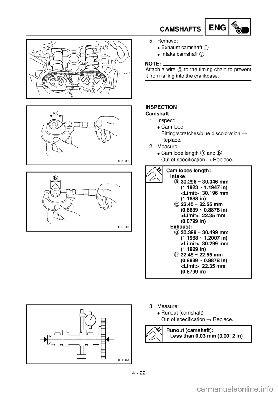
5. Remove:
lExhaust camshaft 1
lIntake camshaft 2
NOTE:
Attach a wire 3 to the timing chain to prevent
it from falling into the crankcase.
INSPECTION
Camshaft
1. Inspect:
lCam lobe
Pitting/scratches/blue discoloration ®
Replace.
2. Measure:
lCam lobe length a and b
Out of specification ® Replace.
Cam lobes length:
Intake:
a30.296 ~ 30.346 mm
(1.1923 ~ 1.1947 in)
(1.1888 in)
b22.45 ~ 22.55 mm
(0.8839 ~ 0.8878 in)
(0.8799 in)
Exhaust:
a30.399 ~ 30.499 mm
(1.1968 ~ 1.2007 in)
(1.1929 in)
b22.45 ~ 22.55 mm
(0.8839 ~ 0.8878 in)
(0.8799 in)
3. Measure:
lRunout (camshaft)
Out of specification ® Replace.
Runout (camshaft):
Less than 0.03 mm (0.0012 in)
Page 300 of 656
4 - 23
ENGCAMSHAFTS
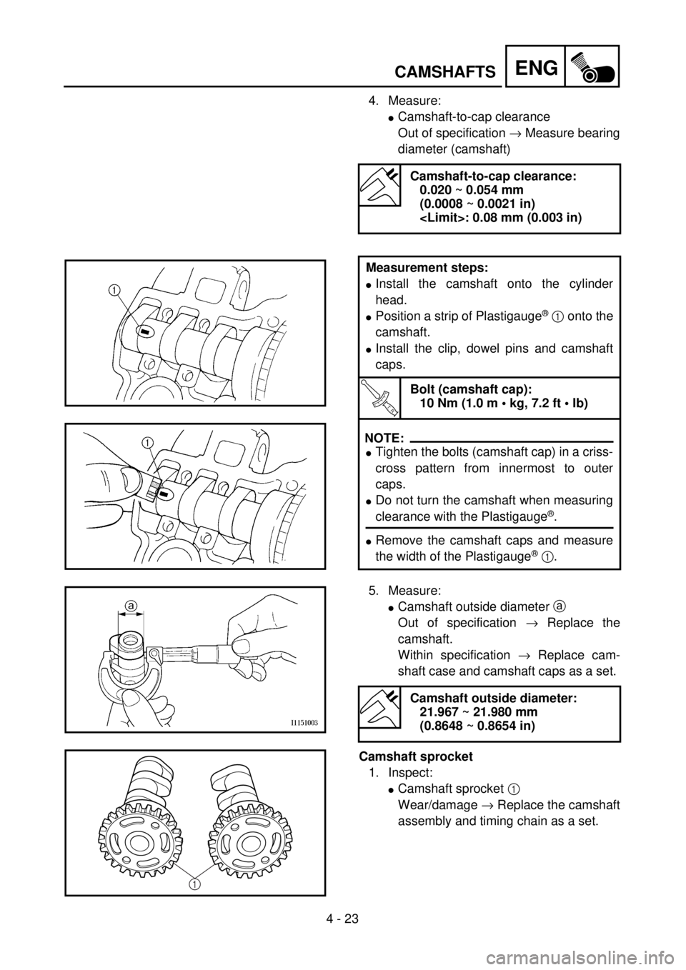
4. Measure:
lCamshaft-to-cap clearance
Out of specification ® Measure bearing
diameter (camshaft)
Camshaft-to-cap clearance:
0.020 ~ 0.054 mm
(0.0008 ~ 0.0021 in)
Measurement steps:
lInstall the camshaft onto the cylinder
head.
lPosition a strip of Plastigauge® 1 onto the
camshaft.
lInstall the clip, dowel pins and camshaft
caps.
T R..
Bolt (camshaft cap):
10 Nm (1.0 m • kg, 7.2 ft • lb)
NOTE:
lTighten the bolts (camshaft cap) in a criss-
cross pattern from innermost to outer
caps.
lDo not turn the camshaft when measuring
clearance with the Plastigauge®.
lRemove the camshaft caps and measure
the width of the Plastigauge
® 1.
5. Measure:
lCamshaft outside diameter a
Out of specification ® Replace the
camshaft.
Within specification ® Replace cam-
shaft case and camshaft caps as a set.
Camshaft sprocket
1. Inspect:
lCamshaft sprocket 1
Wear/damage ® Replace the camshaft
assembly and timing chain as a set.
Camshaft outside diameter:
21.967 ~ 21.980 mm
(0.8648 ~ 0.8654 in)
1
Page 320 of 656
4 - 33
ENGVALVES AND VALVE SPRINGS
REMOVAL POINTS
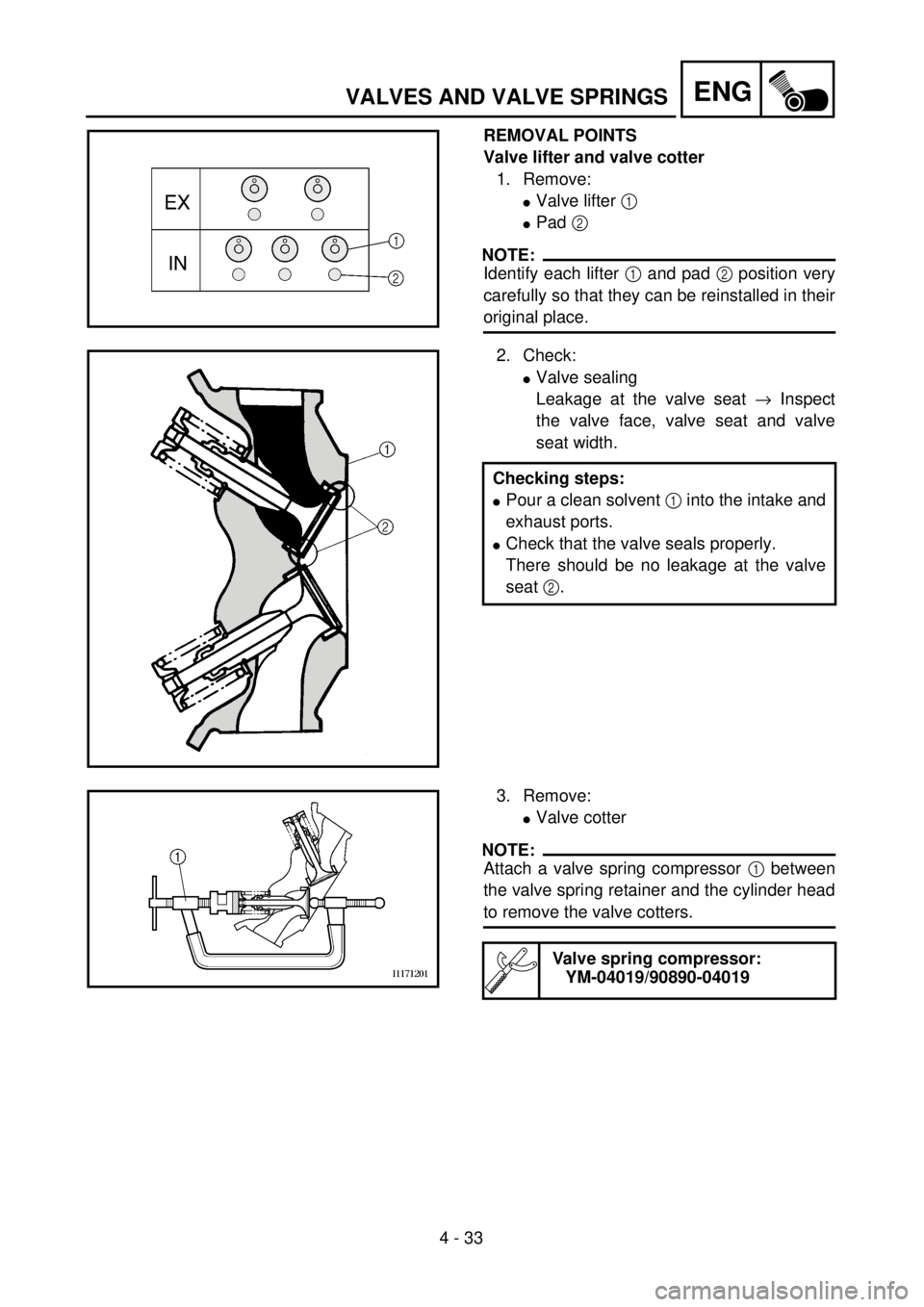
Valve lifter and valve cotter
1. Remove:
lValve lifter 1
lPad 2
NOTE:
Identify each lifter 1 and pad 2 position very
carefully so that they can be reinstalled in their
original place.
2. Check:
lValve sealing
Leakage at the valve seat ® Inspect
the valve face, valve seat and valve
seat width.
Checking steps:
lPour a clean solvent 1 into the intake and
exhaust ports.
lCheck that the valve seals properly.
There should be no leakage at the valve
seat 2.
3. Remove:
lValve cotter
NOTE:
Attach a valve spring compressor 1 between
the valve spring retainer and the cylinder head
to remove the valve cotters.
Valve spring compressor:
YM-04019/90890-04019