fuel YAMAHA YZ250F 2001 Betriebsanleitungen (in German)
[x] Cancel search | Manufacturer: YAMAHA, Model Year: 2001, Model line: YZ250F, Model: YAMAHA YZ250F 2001Pages: 656, PDF-Größe: 24.86 MB
Page 6 of 656

IMPORTANT NOTICE
THIS MACHINE IS DESIGNED STRICTLY
FOR COMPETITION USE, ONLY ON A
CLOSED COURSE. It is illegal for this
machine to be operated on any public street,
road, or highway. Off-road use on public lands
may also be illegal. Please check local regula-
tions before riding.
1. THIS MACHINE IS TO BE OPERATED
BY AN EXPERIENCED RIDER ONLY.
Do not attempt to operate this
machine at maximum power until you
are totally familiar with its character-
istics.
2. THIS MACHINE IS DESIGNED TO BE
RIDDEN BY THE OPERATOR ONLY.
Do not carry passengers on this
machine.
3. ALWAYS WEAR PROTECTIVE
APPAREL.
When operating this machine, always
wear an approved helmet with gog-
gles or a face shield. Also wear heavy
boots, gloves, and protective cloth-
ing. Always wear proper fitting cloth-
ing that will not be caught in any of
the moving parts or controls of the
machine.
4. ALWAYS MAINTAIN YOUR MACHINE
IN PROPER WORKING ORDER.
For safety and reliability, the machine
must be properly maintained. Always
perform the pre-operation checks
indicated in this manual. Correcting a
mechanical problem before you ride
may prevent an accident.
5. GASOLINE IS HIGHLY FLAMMABLE.
Always turn off the engine while refu-
eling. Take care to not spill any gaso-
line on the engine or exhaust system.
Never refuel in the vicinity of an open
flame, or while smoking.
SAFETY INFORMATION
Page 8 of 656

6. GASOLINE CAN CAUSE INJURY.
If you should swallow some gasoline,
inhale excess gasoline vapors, or
allow any gasoline to get into your
eyes, contact a doctor immediately. If
any gasoline spills onto your skin or
clothing, immediately wash skin areas
with soap and water, and change your
clothes.
7. ONLY OPERATE THE MACHINE IN AN
AREA WITH ADEQUATE VENTILA-
TION.
Never start the engine or let it run for
any length of time in an enclosed area.
Exhaust fumes are poisonous. These
fumes contain carbon monoxide,
which by itself is odorless and color-
less. Carbon monoxide is a dangerous
gas which can cause unconscious-
ness or can be lethal.
8. PARK THE MACHINE CAREFULLY;
TURN OFF THE ENGINE.
Always turn off the engine if you are
going to leave the machine. Do not
park the machine on a slope or soft
ground as it may fall over.
9. THE ENGINE EXHAUST PIPE, MUF-
FLER, AND OIL TANK WILL BE VERY
HOT AFTER THE ENGINE HAS BEEN
RUN.
Be careful not to touch them or to
allow any clothing item to contact
them during inspection or repair.
10. PROPERLY SECURE THE MACHINE
BEFORE TRANSPORTING IT.
When transporting the machine in
another vehicle, always be sure it is
properly secured and in an upright
position and that the fuel cock is in
the “OFF” position. Otherwise, fuel
may leak out of the carburetor or fuel
tank.
Page 10 of 656

EC050000
TO THE NEW OWNER
This manual will provide you with a good basic
understanding of features, operation, and
basic maintenance and inspection items of this
machine. Please read this manual carefully
and completely before operating your new
machine. If you have any questions regarding
the operation or maintenance of your machine,
please consult your Yamaha dealer.
NOTE:
This manual should be considered a perma-
nent part of this machine and should remain
with it even if the machine is subsequently
sold.
EC060000
NOTICE
Some data in this manual may become out-
dated due to improvements made to this
model in the future. If there is any question
you have regarding this manual or your
machine, please consult your Yamaha
dealer.
EC070001
F.I.M. MACHINE WEIGHTS:
Weights of machines without fuel
The minimum weights for motocross
machines are:
for the class 125 cc....................... minimum
88 kg (194 lb)
for the class 250 cc....................... minimum
98 kg (216 lb)
for the class 500 cc....................... minimum
102 kg (225 lb)
In modifying your machine (e.g., for weight
reduction), take note of the above limits of
weight.
Page 20 of 656

EC0A0000
CONTENTS
CHAPTER 1
GENERAL INFORMATION
DESCRIPTION
.......................................... 1-1
MACHINE IDENTIFICATION
.................... 1-2
IMPORTANT INFORMATION
................... 1-3
CHECKING OF CONNECTION
................ 1-6
SPECIAL TOOLS
..................................... 1-7
CONTROL FUNCTIONS
......................... 1-10
FUEL
....................................................... 1-13
STARTING AND BREAK-IN
................... 1-14
TORQUE-CHECK POINTS
..................... 1-18
CLEANING AND STORAGE
.................. 1-19
CHAPTER 2
SPECIFICATIONS
GENERAL SPECIFICATIONS
.................. 2-1
MAINTENANCE SPECIFICATIONS
......... 2-4
GENERAL TORQUE
SPECIFICATIONS
.................................. 2-17
DEFINITION OF UNITS
.......................... 2-17
CABLE ROUTING DIAGRAM
................ 2-18
CHAPTER 3
REGULAR INSPECTION AND
ADJUSTMENTS
MAINTENANCE INTERVALS
.................. 3-1
PRE-OPERATION INSPECTION AND
MAINTENANCE
........................................ 3-4
ENGINE
..................................................... 3-5
CHASSIS
................................................ 3-25
ELECTRICAL
.......................................... 3-46
Page 22 of 656

CHAPTER 4
ENGINE
SEAT, FUEL TANK
AND SIDE COVERS
................................. 4-1
EXHAUST PIPE AND SILENCER
............ 4-2
RADIATOR
............................................... 4-4
CARBURETOR
......................................... 4-7
CAMSHAFTS
.......................................... 4-19
CYLINDER HEAD
................................... 4-28
VALVES AND VALVE SPRINGS
........... 4-32
CYLINDER AND PISTON
....................... 4-41
CLUTCH
.................................................. 4-48
OIL FILTER ELEMENT,
WATER PUMP AND RIGHT
CRANKCASE COVER
............................ 4-55
BALANCER
............................................ 4-62
OIL PUMP
............................................... 4-65
KICK SHAFT AND SHIFT SHAFT
......... 4-70
CDI MAGNETO
....................................... 4-77
ENGINE REMOVAL
................................ 4-81
CRANKCASE AND CRANKSHAFT
....... 4-86
TRANSMISSION, SHIFT CAM
AND SHIFT FORK
.................................. 4-95
CHAPTER 5
CHASSIS
FRONT WHEEL AND REAR WHEEL
...... 5-1
FRONT BRAKE AND REAR BRAKE
.... 5-10
FRONT FORK
......................................... 5-27
HANDLEBAR
.......................................... 5-40
STEERING
.............................................. 5-45
SWINGARM
............................................ 5-50
REAR SHOCK ABSORBER
................... 5-57
Page 26 of 656
GEN
INFO
1 - 1
DESCRIPTION
EC100000
GENERAL INFORMATION
EC110000
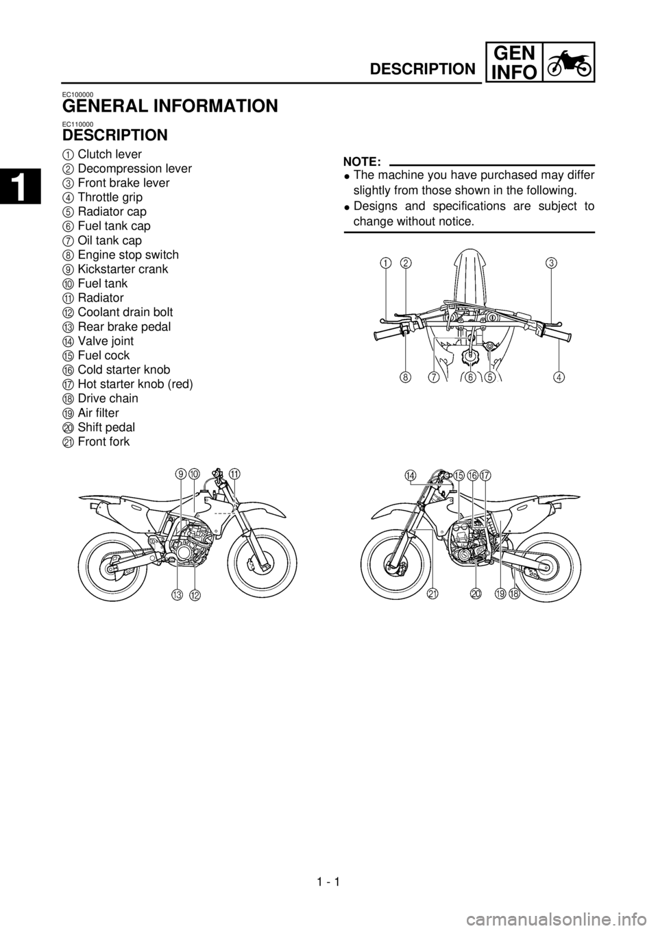
DESCRIPTION
1
Clutch lever
2
Decompression lever
3
Front brake lever
4
Throttle grip
5
Radiator cap
6
Fuel tank cap
7
Oil tank cap
8
Engine stop switch
9
Kickstarter crank
0
Fuel tank
A
Radiator
B
Coolant drain bolt
C
Rear brake pedal
D
Valve joint
E
Fuel cock
F
Cold starter knob
G
Hot starter knob (red)
H
Drive chain
I
Air filter
J
Shift pedal
K
Front fork
NOTE:
l
The machine you have purchased may differ
slightly from those shown in the following.
l
Designs and specifications are subject to
change without notice.
1
Page 54 of 656
1 - 12
GEN
INFO
CONTROL FUNCTIONS
EC158001
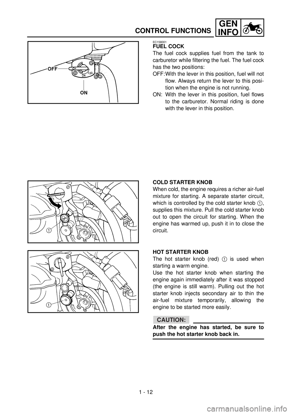
FUEL COCK
The fuel cock supplies fuel from the tank to
carburetor while filtering the fuel. The fuel cock
has the two positions:
OFF:With the lever in this position, fuel will not
flow. Always return the lever to this posi-
tion when the engine is not running.
ON: With the lever in this position, fuel flows
to the carburetor. Normal riding is done
with the lever in this position.
COLD STARTER KNOB
When cold, the engine requires a richer air-fuel
mixture for starting. A separate starter circuit,
which is controlled by the cold starter knob 1,
supplies this mixture. Pull the cold starter knob
out to open the circuit for starting. When the
engine has warmed up, push it in to close the
circuit.
HOT STARTER KNOB
The hot starter knob (red) 1 is used when
starting a warm engine.
Use the hot starter knob when starting the
engine again immediately after it was stopped
(the engine is still warm). Pulling out the hot
starter knob injects secondary air to thin the
air-fuel mixture temporarily, allowing the
engine to be started more easily.
CAUTION:
After the engine has started, be sure to
push the hot starter knob back in.
Page 56 of 656
1 - 13
GEN
INFO
CONTROL FUNCTIONS/FUEL
EC15F000
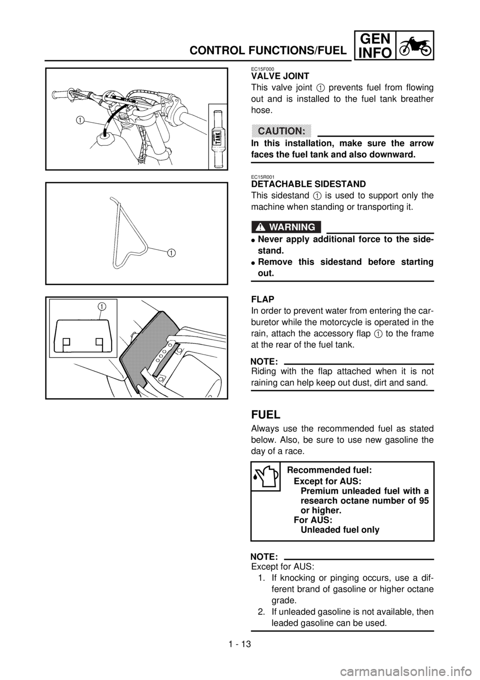
VALVE JOINT
This valve joint 1 prevents fuel from flowing
out and is installed to the fuel tank breather
hose.
CAUTION:
In this installation, make sure the arrow
faces the fuel tank and also downward.
EC15R001
DETACHABLE SIDESTAND
This sidestand 1 is used to support only the
machine when standing or transporting it.
WARNING
lNever apply additional force to the side-
stand.
lRemove this sidestand before starting
out.
FLAP
In order to prevent water from entering the car-
buretor while the motorcycle is operated in the
rain, attach the accessory flap 1 to the frame
at the rear of the fuel tank.
NOTE:
Riding with the flap attached when it is not
raining can help keep out dust, dirt and sand.
FUEL
Always use the recommended fuel as stated
below. Also, be sure to use new gasoline the
day of a race.
NOTE:
Except for AUS:
1. If knocking or pinging occurs, use a dif-
ferent brand of gasoline or higher octane
grade.
2. If unleaded gasoline is not available, then
leaded gasoline can be used.
Recommended fuel:
Except for AUS:
Premium unleaded fuel with a
research octane number of 95
or higher.
For AUS:
Unleaded fuel only
Page 58 of 656
1 - 14
GEN
INFO
STARTING AND BREAK-IN
STARTING AND BREAK-IN
WARNING
Never start or run the engine in a closed
area. The exhaust fumes are poisonous;
they can cause loss of consciousness and
death in a very short time. Always operate
the machine in a well-ventilated area.
CAUTION:
lThe carburetor on this motorcycle has a
built-in accelerator pump. Therefore,
when starting the engine, do not operate
the throttle or the spark plug will foul.
lUnlike a two-stroke engine, this engine
cannot be kick started when the throttle is
open because the kick starter may kick
back. Also, if the throttle is open the air/
fuel mixture may be too lean for the
engine to start.
lNever use the decompression lever after
the engine is started. The engine may be
damaged if you use the decompression
lever while it is running.
lBefore starting the machine, perform the
checks in the pre-operation check list.
STARTING A COLD ENGINE
1. Inspect the coolant level.
2. Turn the fuel cock to “ON”.
3. Shift the transmission into neutral.
4. Fully open the cold starter knob.
5. Without pulling in the decompression
lever, slowly depress the kickstarter
crank until the compression stroke is
found. When considerable resistance of
the kickstarter crank is felt, the engine is
on the compression stroke. If the engine
is on the exhaust stroke, resistance will
only be felt when the kickstarter crank is
initially depressed, not through the entire
range of depression (as when the engine
is on the compression stroke); therefore,
depress the kickstarter crank a few more
times.
Page 60 of 656
1 - 15
GEN
INFO
STARTING AND BREAK-IN
6. Pull the decompression lever to the han-
dlebar and depress the kickstarter crank
10 ~ 20˚.
7. Release the decompression lever and
return the kickstarter crank to its original
position and then kick the kickstarter
crank.
WARNING
Do not open the throttle while kicking the
kickstarter crank. Otherwise, the kick
starter may kick back.
8. Return the cold starter knob to its original
position and run the engine at 3,000 ~
5,000 r/min for 1 or 2 minutes.
NOTE:
Since this model is equipped with an accelera-
tor pump, if the engine is raced (the throttle
opened and closed), the air/fuel mixture will be
too rich and the engine may stall. Also unlike a
two-stroke engine, this model can idle.
CAUTION:
Do not warm up the engine for extended
periods of time.