engine oil YAMAHA YZ250F 2001 Manuale duso (in Italian)
[x] Cancel search | Manufacturer: YAMAHA, Model Year: 2001, Model line: YZ250F, Model: YAMAHA YZ250F 2001Pages: 656, PDF Dimensioni: 24.86 MB
Page 194 of 656

3 - 18
INSP
ADJ
OIL PRESSURE INSPECTION
1. Check:
lOil pressure
Checking steps:
lSlightly loosen the oil pressure check bolt
1.
lStart the engine and keep it idling until oil
starts to seep from the oil pressure check
bolt. If no oil comes out after one minute,
turn the engine off so it will not seize.
lCheck oil passages and oil pump for dam-
age or leakage.
lStart the engine after solving the prob-
lem(s) and recheck the oil pressure.
lTighten the oil pressure check bolt.
T R..
Oil pressure check bolt:
18 Nm (1.8 m • kg, 13 ft • lb)
PILOT SCREW ADJUSTMENT
1. Adjust:
lPilot screw 1
Adjustment steps:
NOTE:
To optimize the fuel flow at a smaller throttle
opening, each machine’s pilot screw has
been individually set at the factory. Before
adjusting the pilot screw, turn it in fully and
count the number of turns. Record this num-
ber as the factory-set number of turns out.
lTurn in the pilot screw until it is lightly
seated.
lTurn out the pilot screw by the factory-set
number of turns.
Pilot screw:
1-3/4 turns out (example)
OIL PRESSURE INSPECTION/
PILOT SCREW ADJUSTMENT
Page 204 of 656
3 - 23
INSP
ADJ
VALVE CLEARANCE INSPECTION AND ADJUSTMENT
lLocate the rounded-off value and the
measured valve clearance in the chart
“PAD SELECTION TABLE”. The field
where these two coordinates intersect
shows the new pad number to use.
NOTE:
Use the new pad number only as a guide
when verifying the valve clearance adjust-
ment.
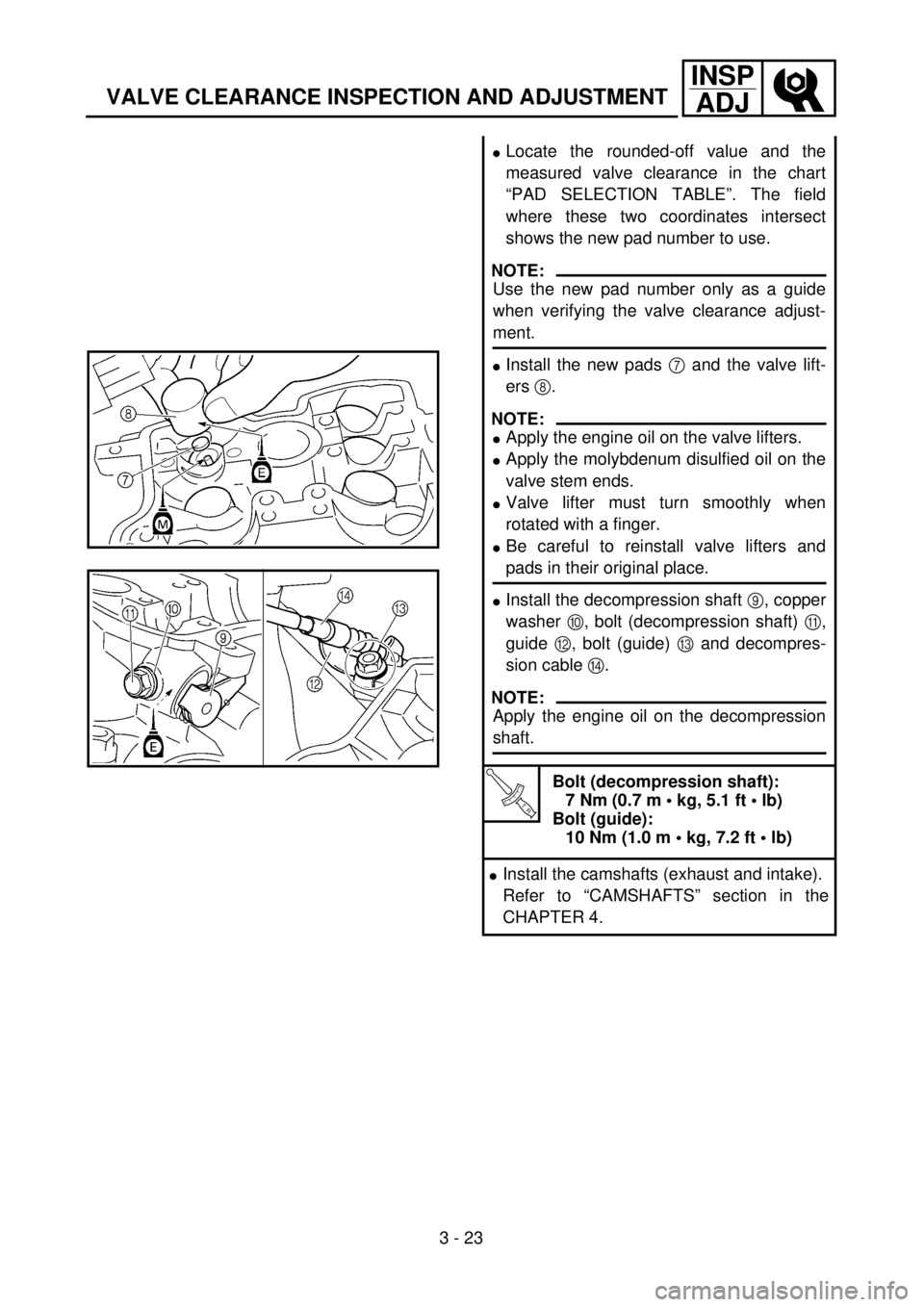
lInstall the new pads 7 and the valve lift-
ers 8.
NOTE:
lApply the engine oil on the valve lifters.
lApply the molybdenum disulfied oil on the
valve stem ends.
lValve lifter must turn smoothly when
rotated with a finger.
lBe careful to reinstall valve lifters and
pads in their original place.
lInstall the decompression shaft 9, copper
washer 0, bolt (decompression shaft) A,
guide B, bolt (guide) C and decompres-
sion cable D.
NOTE:
Apply the engine oil on the decompression
shaft.
T R..
Bolt (decompression shaft):
7 Nm (0.7 m • kg, 5.1 ft • lb)
Bolt (guide):
10 Nm (1.0 m • kg, 7.2 ft • lb)
lInstall the camshafts (exhaust and intake).
Refer to “CAMSHAFTS” section in the
CHAPTER 4.
Page 226 of 656

3 - 33
INSP
ADJ
DRIVE CHAIN SLACK ADJUSTMENT
5. Install:
lDrive chain 1
lJoint 2
lMaster link clip 3
CAUTION:
Be sure to install the master link clip to the
direction as shown.
aTurning direction
6. Lubricate:
lDrive chain
Drive chain lubricant:
SAE 10W-30 motor oil or suit-
able chain lubricants
EC36A060
DRIVE CHAIN SLACK ADJUSTMENT
1. Elevate the rear wheel by placing the
suitable stand under the engine.
2. Check:
lDrive chain slack a
Above the seal guard installation bolt.
Out of specification ® Adjust.
NOTE:
Before checking and/or adjusting, rotate the
rear wheel through several revolutions and
check the slack several times to find the tight-
est point. Check and/or adjust chain slack with
rear wheel in this “tight chain” position.
Drive chain slack:
40 ~ 50 mm (1.6 ~ 2.0 in)
Page 228 of 656
3 - 34
INSP
ADJ
FRONT FORK INSPECTION
3. Adjust:
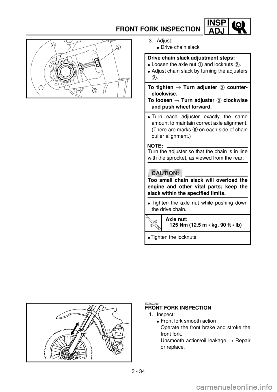
lDrive chain slack
Drive chain slack adjustment steps:
lLoosen the axle nut 1 and locknuts 2.
lAdjust chain slack by turning the adjusters
3.
To tighten ® Turn adjuster 3 counter-
clockwise.
To loosen ® Turn adjuster 3 clockwise
and push wheel forward.
lTurn each adjuster exactly the same
amount to maintain correct axle alignment.
(There are marks a on each side of chain
puller alignment.)
NOTE:
Turn the adjuster so that the chain is in line
with the sprocket, as viewed from the rear.
CAUTION:
Too small chain slack will overload the
engine and other vital parts; keep the
slack within the specified limits.
lTighten the axle nut while pushing down
the drive chain.
T R..
Axle nut:
125 Nm (12.5 m • kg, 90 ft • lb)
lTighten the locknuts.
EC36C000
FRONT FORK INSPECTION
1. Inspect:
lFront fork smooth action
Operate the front brake and stroke the
front fork.
Unsmooth action/oil leakage ® Repair
or replace.
Page 304 of 656
4 - 25
ENGCAMSHAFTS
CAUTION:
Do not turn the crankshaft during the
camshaft installation. Damage or
improper valve timing will result.
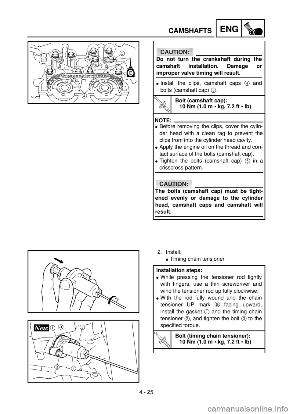
lInstall the clips, camshaft caps 4 and
bolts (camshaft cap) 5.
T R..
Bolt (camshaft cap):
10 Nm (1.0 m • kg, 7.2 ft • lb)
NOTE:
lBefore removing the clips, cover the cylin-
der head with a clean rag to prevent the
clips from into the cylinder head cavity.
lApply the engine oil on the thread and con-
tact surface of the bolts (camshaft cap).
lTighten the bolts (camshaft cap) 5 in a
crisscross pattern.
CAUTION:
The bolts (camshaft cap) must be tight-
ened evenly or damage to the cylinder
head, camshaft caps and camshaft will
result.
2. Install:
lTiming chain tensioner
Installation steps:
lWhile pressing the tensioner rod lightly
with fingers, use a thin screwdriver and
wind the tensioner rod up fully clockwise.
lWith the rod fully wound and the chain
tensioner UP mark a facing upward,
install the gasket 1 and the timing chain
tensioner 2, and tighten the bolt 3 to the
specified torque.
T R..
Bolt (timing chain tensioner):
10 Nm (1.0 m • kg, 7.2 ft • lb)
Page 310 of 656

4 - 28
ENGCYLINDER HEAD
CYLINDER HEAD
Extent of removal:1 Cylinder head removal
Extent of removal Order Part name Q’ty Remarks
CYLINDER HEAD REMOVAL
Preparation for removal Seat and fuel tank Refer to “SEAT, FUEL TANK AND SIDE
COVERS” section.
Exhaust pipe and silencer Refer to “EXHAUST PIPE AND
SILENCER” section.
Radiator hose 1 Disconnect at cylinder head side.
Carburetor Refer to “CARBURETOR” section.
Camshaft Refer to “CAMSHAFTS” section.
Upper engine bracket Refer to “ENGINE REMOVAL” section.
1 Radiator pipe 1
2 Decompression cable guide 1
3 Oil delivery pipe 1
4 Nut 2
5 Bolt [L=135 mm (5.31 in)] 2
6 Bolt [L=145 mm (5.71 in)] 2
7 Cylinder head 1 Disconnect the decompression cable.
8 Timing chain guard (exhaust side) 1
9 Bolt (decompression shaft) 1
10 Decompression shaft 1
1
Page 314 of 656

4 - 30
ENGCYLINDER HEAD
ASSEMBLY AND INSTALLATION
Cylinder head
1. Install:
lDecompression shaft 1
lCopper washer 2
lBolt (decompression shaft) 3
NOTE:
Apply the engine oil on the decompression
shaft.
T R..10 Nm (1.0 m · kg, 7.2 ft · lb)
2. Install:
lDowel pin 1
lCylinder head gasket 2
lTiming chain guide (exhaust side) 3
lDecompression cable 4
lCylinder head 5
NOTE:
lInstall the decompression cable to the cylin-
der head, and then to the cylinder.
lWhile pulling up the timing chain, install the
timing chain guide (exhaust side) and cylin-
der head.
Page 334 of 656
4 - 40
ENGVALVES AND VALVE SPRINGS
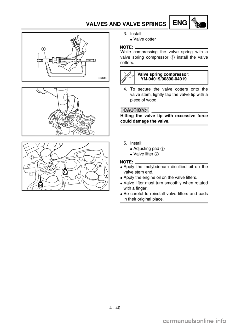
3. Install:
lValve cotter
NOTE:
While compressing the valve spring with a
valve spring compressor 1 install the valve
cotters.
4. To secure the valve cotters onto the
valve stem, lightly tap the valve tip with a
piece of wood.
CAUTION:
Hitting the valve tip with excessive force
could damage the valve.
Valve spring compressor:
YM-04019/90890-04019
5. Install:
lAdjusting pad 1
lValve lifter 2
NOTE:
lApply the molybdenum disulfied oil on the
valve stem end.
lApply the engine oil on the valve lifters.
lValve lifter must turn smoothly when rotated
with a finger.
lBe careful to reinstall valve lifters and pads
in their original place.
Page 344 of 656
4 - 45
ENGCYLINDER AND PISTON
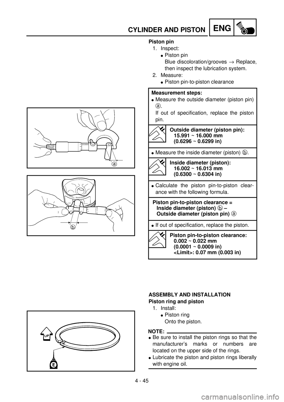
Piston pin
1. Inspect:
lPiston pin
Blue discoloration/grooves ® Replace,
then inspect the lubrication system.
2. Measure:
lPiston pin-to-piston clearance
ASSEMBLY AND INSTALLATION
Piston ring and piston
1. Install:
lPiston ring
Onto the piston.
NOTE:
lBe sure to install the piston rings so that the
manufacturer’s marks or numbers are
located on the upper side of the rings.
lLubricate the piston and piston rings liberally
with engine oil. Measurement steps:
lMeasure the outside diameter (piston pin)
a.
If out of specification, replace the piston
pin.
Outside diameter (piston pin):
15.991 ~ 16.000 mm
(0.6296 ~ 0.6299 in)
lMeasure the inside diameter (piston) b.
Inside diameter (piston):
16.002 ~ 16.013 mm
(0.6300 ~ 0.6304 in)
lCalculate the piston pin-to-piston clear-
ance with the following formula.
Piston pin-to-piston clearance =
Inside diameter (piston) b –
Outside diameter (piston pin) a
lIf out of specification, replace the piston.
Piston pin-to-piston clearance:
0.002 ~ 0.022 mm
(0.0001 ~ 0.0009 in)
Page 346 of 656
4 - 46
ENGCYLINDER AND PISTON
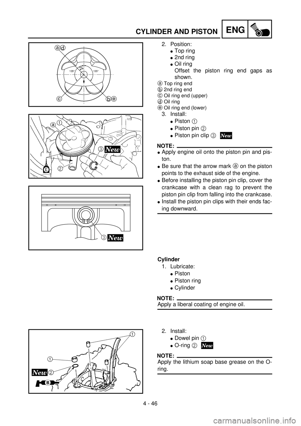
2. Position:
lTop ring
l2nd ring
lOil ring
Offset the piston ring end gaps as
shown.
aTop ring end
b2nd ring end
cOil ring end (upper)
dOil ring
eOil ring end (lower)
3. Install:
lPiston 1
lPiston pin 2
lPiston pin clip 3
NOTE:
lApply engine oil onto the piston pin and pis-
ton.
lBe sure that the arrow mark a on the piston
points to the exhaust side of the engine.
lBefore installing the piston pin clip, cover the
crankcase with a clean rag to prevent the
piston pin clip from falling into the crankcase.
lInstall the piston pin clips with their ends fac-
ing downward.
45¡
135¡135¡
a
b ced
3New
Cylinder
1. Lubricate:
lPiston
lPiston ring
lCylinder
NOTE:
Apply a liberal coating of engine oil.
2. Install:
lDowel pin 1
lO-ring 2
NOTE:
Apply the lithium soap base grease on the O-
ring.