Electric YAMAHA YZ250F 2001 Manuale duso (in Italian)
[x] Cancel search | Manufacturer: YAMAHA, Model Year: 2001, Model line: YZ250F, Model: YAMAHA YZ250F 2001Pages: 656, PDF Dimensioni: 24.86 MB
Page 12 of 656
EC080000
HOW TO USE
THIS MANUAL
EC081000
PARTICULARLY IMPORTANT
INFORMATION
The Safety Alert Symbol means ATTENTION!
BECOME ALERT! YOUR SAFETY IS
INVOLVED!
Failure to follow WARNING instructions could
result in severe injury or death to the machine
operator, a bystander, or a person inspecting
or repairing the machine.
A CAUTION indicates special precautions that
must be taken to avoid damage to the
machine.
NOTE:
A NOTE provides key information to make pro-
cedures easier or clearer.
WARNING
CAUTION:
EC082000
FINDING THE REQUIRED PAGE
1. This manual consists of seven chapters;
“General information”, “Specifications”,
“Regular inspection and adjustments”,
“Engine”, “Chassis”, “Electrical” and
“Tuning”.
2. The table of contents is at the beginning
of the manual. Look over the general lay-
out of the book before finding then
required chapter and item.
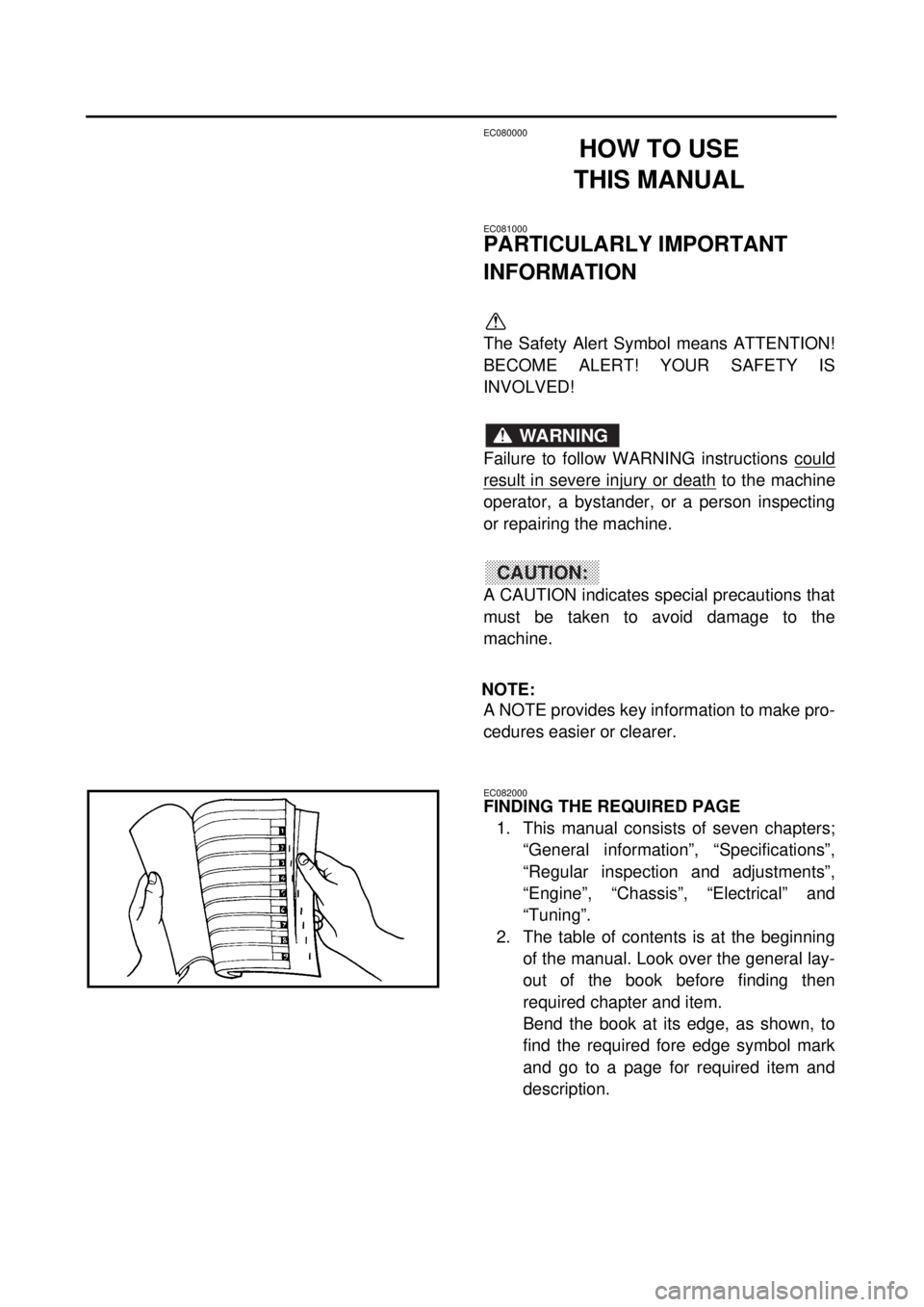
Bend the book at its edge, as shown, to
find the required fore edge symbol mark
and go to a page for required item and
description.
Page 16 of 656
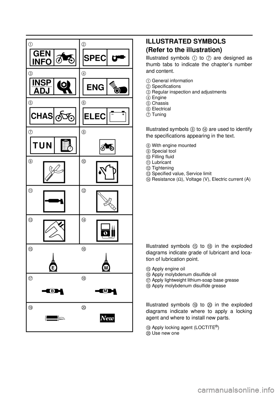
ILLUSTRATED SYMBOLS
(Refer to the illustration)
Illustrated symbols
1
to
7
are designed as
thumb tabs to indicate the chapter’s number
and content.
1
General information
2
Specifications
3
Regular inspection and adjustments
4
Engine
5
Chassis
6
Electrical
7
Tuning
Illustrated symbols
8
to
D
are used to identify
the specifications appearing in the text.
8
With engine mounted
9
Special tool
0
Filling fluid
A
Lubricant
B
Tightening
C
Specified value, Service limit
D
Resistance (
W
), Voltage (V), Electric current (A)
Illustrated symbols
E
to
H
in the exploded
diagrams indicate grade of lubricant and loca-
tion of lubrication point.
E
Apply engine oil
F
Apply molybdenum disulfide oil
G
Apply lightweight lithium-soap base grease
H
Apply molybdenum disulfide grease
Illustrated symbols
I
to
J
in the exploded
diagrams indicate where to apply a locking
agent and where to install new parts.
IApply locking agent (LOCTITE
®)
JUse new one 12
34
56
78
90
AB
CD
EF
GH
IJ
GEN
INFOSPEC
INSP
ADJENG
CHAS–+ELEC
TUN
T R..
EM
BM
Page 18 of 656

EC090010
INDEX
GENERAL INFORMATION
SPECIFICATIONS
REGULAR INSPECTION AND ADJUSTMENTS
ENGINE
CHASSIS
ELECTRICAL
TUNING
Page 20 of 656

EC0A0000
CONTENTS
CHAPTER 1
GENERAL INFORMATION
DESCRIPTION
.......................................... 1-1
MACHINE IDENTIFICATION
.................... 1-2
IMPORTANT INFORMATION
................... 1-3
CHECKING OF CONNECTION
................ 1-6
SPECIAL TOOLS
..................................... 1-7
CONTROL FUNCTIONS
......................... 1-10
FUEL
....................................................... 1-13
STARTING AND BREAK-IN
................... 1-14
TORQUE-CHECK POINTS
..................... 1-18
CLEANING AND STORAGE
.................. 1-19
CHAPTER 2
SPECIFICATIONS
GENERAL SPECIFICATIONS
.................. 2-1
MAINTENANCE SPECIFICATIONS
......... 2-4
GENERAL TORQUE
SPECIFICATIONS
.................................. 2-17
DEFINITION OF UNITS
.......................... 2-17
CABLE ROUTING DIAGRAM
................ 2-18
CHAPTER 3
REGULAR INSPECTION AND
ADJUSTMENTS
MAINTENANCE INTERVALS
.................. 3-1
PRE-OPERATION INSPECTION AND
MAINTENANCE
........................................ 3-4
ENGINE
..................................................... 3-5
CHASSIS
................................................ 3-25
ELECTRICAL
.......................................... 3-46
Page 24 of 656

CHAPTER 6
ELECTRICAL
ELECTRICAL COMPONENTS
AND WIRING DIAGRAM
.......................... 6-1
MAP-CONTROLLED CDI UNIT
................ 6-2
IGNITION SYSTEM
................................... 6-3
THROTTLE POSITION
SENSOR SYSTEM
................................... 6-7
CHAPTER 7
TUNING
ENGINE
..................................................... 7-1
CHASSIS
................................................ 7-11
Page 76 of 656

SPEC
2 - 3
GENERAL SPECIFICATIONS
Brake:
Front brake type Single disc brake
Operation Right hand operation
Rear brake type Single disc brake
Operation Right foot operation
Suspension:
Front suspension Telescopic fork
Rear suspension Swingarm (link type monocross suspension)
Shock absorber:
Front shock absorber Coil spring/oil damper
Rear shock absorber Coil spring/gas, oil damper
Wheel travel:
Front wheel travel 300 mm (11.8 in)
Rear wheel travel 315 mm (12.4 in)
Electrical:
Ignition system CDI magneto
Page 89 of 656
SPEC
2 - 16
MAINTENANCE SPECIFICATIONS
EC212300
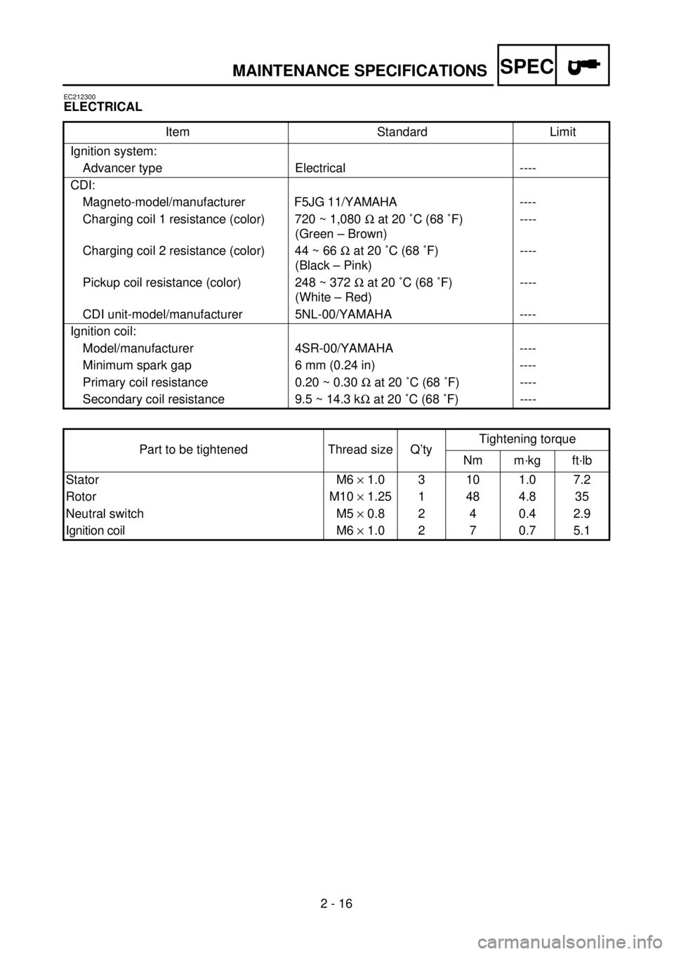
ELECTRICAL
Item Standard Limit
Ignition system:
Advancer type Electrical ----
CDI:
Magneto-model/manufacturer F5JG 11/YAMAHA----
Charging coil 1 resistance (color) 720 ~ 1,080 W at 20 ˚C (68 ˚F)
(Green – Brown)----
Charging coil 2 resistance (color) 44 ~ 66 W at 20 ˚C (68 ˚F)
(Black – Pink)----
Pickup coil resistance (color) 248 ~ 372 W at 20 ˚C (68 ˚F)
(White – Red)----
CDI unit-model/manufacturer 5NL-00/YAMAHA ----
Ignition coil:
Model/manufacturer 4SR-00/YAMAHA ----
Minimum spark gap 6 mm (0.24 in) ----
Primary coil resistance 0.20 ~ 0.30 W at 20 ˚C (68 ˚F) ----
Secondary coil resistance 9.5 ~ 14.3 kW at 20 ˚C (68 ˚F) ----
Part to be tightened Thread size Q’tyTightening torque
Nm m·kg ft·lb
Stator M6 ´ 1.0 3 10 1.0 7.2
Rotor M10 ´ 1.25 1 48 4.8 35
Neutral switch M5 ´ 0.8 2 4 0.4 2.9
Ignition coil M6 ´ 1.0 2 7 0.7 5.1
Page 252 of 656
3 - 46
INSP
ADJ
ELECTRICAL/SPARK PLUG INSPECTION
EC370000
ELECTRICAL
EC371001
SPARK PLUG INSPECTION
1. Remove:
lSpark plug
2. Inspect:
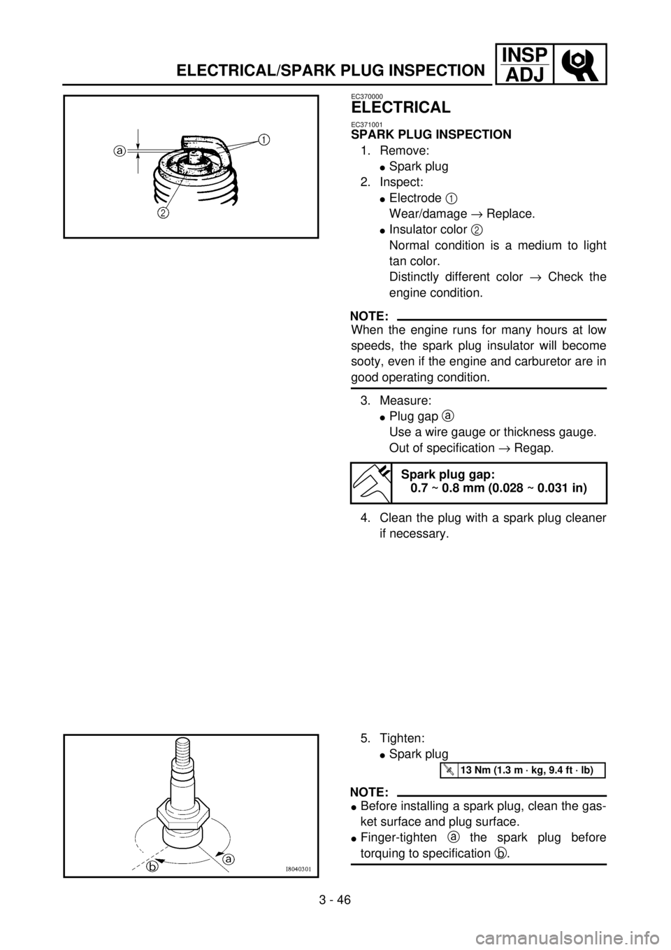
lElectrode 1
Wear/damage ® Replace.
lInsulator color 2
Normal condition is a medium to light
tan color.
Distinctly different color ® Check the
engine condition.
NOTE:
When the engine runs for many hours at low
speeds, the spark plug insulator will become
sooty, even if the engine and carburetor are in
good operating condition.
3. Measure:
lPlug gap a
Use a wire gauge or thickness gauge.
Out of specification ® Regap.
4. Clean the plug with a spark plug cleaner
if necessary.
Spark plug gap:
0.7 ~ 0.8 mm (0.028 ~ 0.031 in)
5. Tighten:
lSpark plug
NOTE:
lBefore installing a spark plug, clean the gas-
ket surface and plug surface.
lFinger-tighten a the spark plug before
torquing to specification b.
T R..13 Nm (1.3 m · kg, 9.4 ft · lb)
Page 580 of 656
6 - 1
–+ELEC
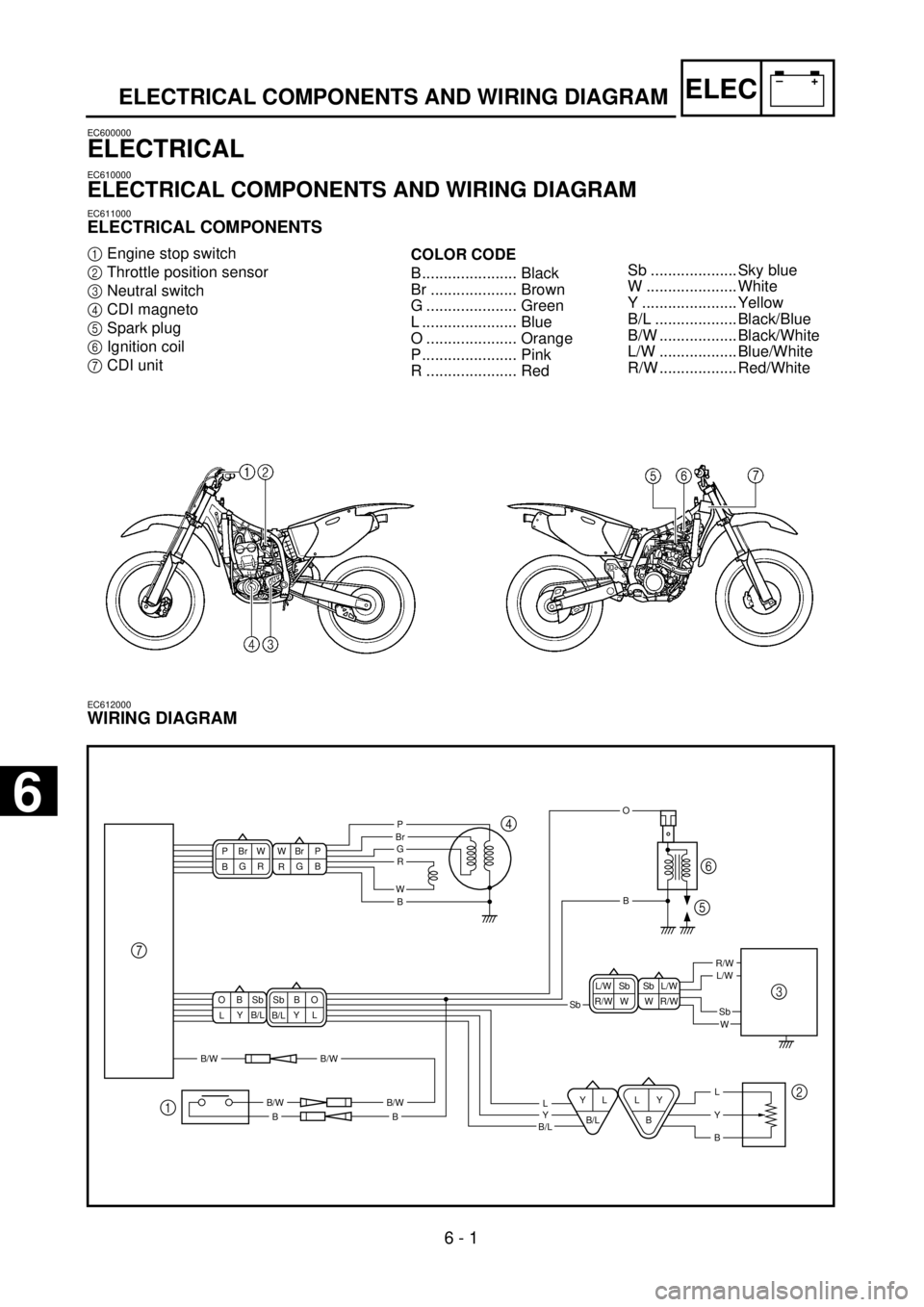
ELECTRICAL COMPONENTS AND WIRING DIAGRAM
EC600000
ELECTRICAL
EC610000
ELECTRICAL COMPONENTS AND WIRING DIAGRAM
EC611000
ELECTRICAL COMPONENTS
1
Engine stop switch
2
Throttle position sensor
3
Neutral switch
4
CDI magneto
5
Spark plug
6
Ignition coil
7
CDI unit
COLOR CODE
B...................... Black
Br .................... Brown
G ..................... Green
L ...................... Blue
O ..................... Orange
P...................... Pink
R ..................... Red
EC612000
WIRING DIAGRAM
7
16
5
2 3 4
LY
BYL
B/LL
G
P
W
R
Y
B
G
BR PBrWG
RB Br WP
R/W WL/W SbW R/W Sb L/WY
B/LL Sb B OY
LB/L B OSbSb
L/WR/W
WSb
B/L
B/WB/W
B/WB/W
Br
BB
LBBY
O
Sb .................... Sky blue
W ..................... White
Y ...................... Yellow
B/L ................... Black/Blue
B/W .................. Black/White
L/W .................. Blue/White
R/W .................. Red/White
6
Page 594 of 656
6 - 6
–+ELECIGNITION SYSTEM
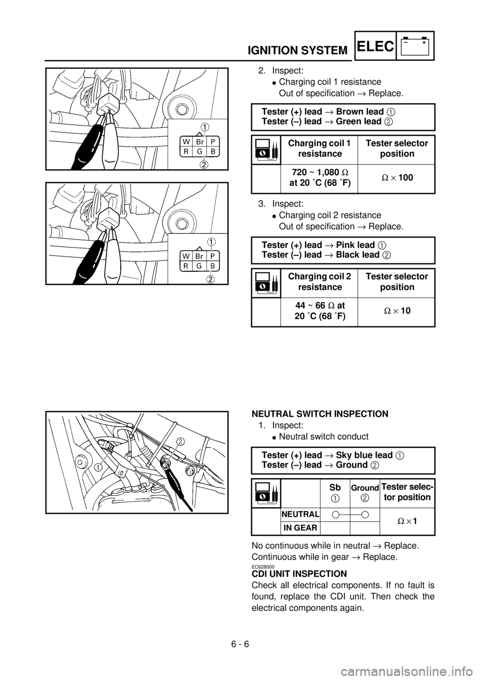
2. Inspect:
lCharging coil 1 resistance
Out of specification ® Replace.
3. Inspect:
lCharging coil 2 resistance
Out of specification ® Replace. Tester (+) lead ® Brown lead 1
Tester (–) lead ® Green lead 2
Charging coil 1
resistanceTester selector
position
720 ~ 1,080 W
at 20 ˚C (68 ˚F)W ´ 100
Tester (+) lead ® Pink lead 1
Tester (–) lead ® Black lead 2
Charging coil 2
resistanceTester selector
position
44 ~ 66 W at
20 ˚C (68 ˚F)W ´ 10
NEUTRAL SWITCH INSPECTION
1. Inspect:
lNeutral switch conduct
No continuous while in neutral ® Replace.
Continuous while in gear ® Replace.
EC628000
CDI UNIT INSPECTION
Check all electrical components. If no fault is
found, replace the CDI unit. Then check the
electrical components again.Tester (+) lead ® Sky blue lead 1
Tester (–) lead ® Ground 2
Sb
1Ground
2Tester selec-
tor position
NEUTRALW ´ 1IN GEAR