check oil YAMAHA YZ250F 2001 Notices Demploi (in French)
[x] Cancel search | Manufacturer: YAMAHA, Model Year: 2001, Model line: YZ250F, Model: YAMAHA YZ250F 2001Pages: 656, PDF Size: 24.86 MB
Page 594 of 656
6 - 6
–+ELECIGNITION SYSTEM
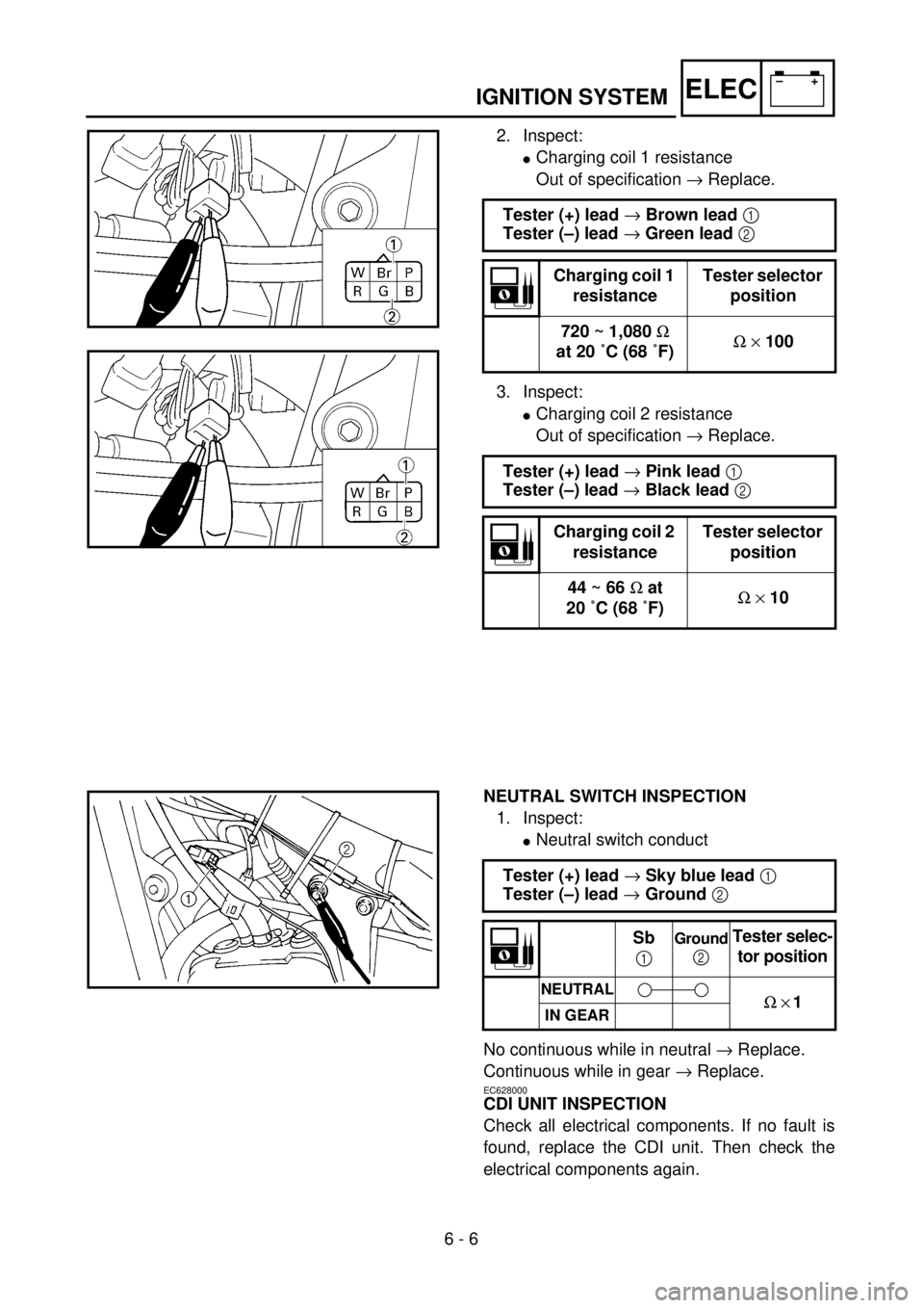
2. Inspect:
lCharging coil 1 resistance
Out of specification ® Replace.
3. Inspect:
lCharging coil 2 resistance
Out of specification ® Replace. Tester (+) lead ® Brown lead 1
Tester (–) lead ® Green lead 2
Charging coil 1
resistanceTester selector
position
720 ~ 1,080 W
at 20 ˚C (68 ˚F)W ´ 100
Tester (+) lead ® Pink lead 1
Tester (–) lead ® Black lead 2
Charging coil 2
resistanceTester selector
position
44 ~ 66 W at
20 ˚C (68 ˚F)W ´ 10
NEUTRAL SWITCH INSPECTION
1. Inspect:
lNeutral switch conduct
No continuous while in neutral ® Replace.
Continuous while in gear ® Replace.
EC628000
CDI UNIT INSPECTION
Check all electrical components. If no fault is
found, replace the CDI unit. Then check the
electrical components again.Tester (+) lead ® Sky blue lead 1
Tester (–) lead ® Ground 2
Sb
1Ground
2Tester selec-
tor position
NEUTRALW ´ 1IN GEAR
Page 596 of 656
–+ELEC
6 - 7
THROTTLE POSITION SENSOR SYSTEM
THROTTLE POSITION SENSOR SYSTEM
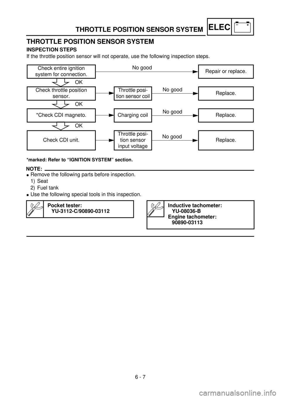
INSPECTION STEPS
If the throttle position sensor will not operate, use the following inspection steps.
*marked: Refer to “IGNITION SYSTEM” section.
NOTE:
lRemove the following parts before inspection.
1) Seat
2) Fuel tank
lUse the following special tools in this inspection.
Pocket tester:
YU-3112-C/90890-03112Inductive tachometer:
YU-08036-B
Engine tachometer:
90890-03113
Check entire ignition
system for connection.Repair or replace.
Check throttle position
sensor.Throttle posi-
tion sensor coilReplace.
*Check CDI magneto. Charging coil Replace.
Check CDI unit.Throttle posi-
tion sensor
input voltageReplace.
OK
OK
OK
No good
No good
No good
No good
Page 600 of 656
6 - 8
–+ELECTHROTTLE POSITION SENSOR SYSTEM
EC624000
COUPLERS AND LEADS CONNECTION
INSPECTION
1. Check:
lCouplers and leads connection
Rust/dust/looseness/short-circuit ®
Repair or replace.
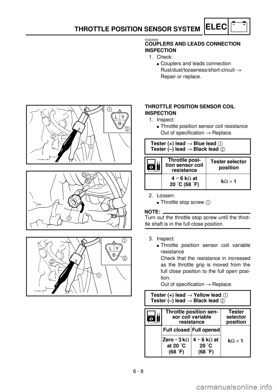
THROTTLE POSITION SENSOR COIL
INSPECTION
1. Inspect:
lThrottle position sensor coil resistance
Out of specification ® Replace.
2. Loosen:
lThrottle stop screw 1
NOTE:
Turn out the throttle stop screw until the throt-
tle shaft is in the full close position.Tester (+) lead ® Blue lead 1
Tester (–) lead ® Black lead 2
Throttle posi-
tion sensor coil
resistanceTester selector
position
4 ~ 6 kW at
20 ˚C (68 ˚F)kW ´ 1
3. Inspect:
lThrottle position sensor coil variable
resistance
Check that the resistance in increased
as the throttle grip is moved from the
full close position to the full open posi-
tion.
Out of specification ® Replace.
Tester (+) lead ® Yellow lead 1
Tester (–) lead ® Black lead 2
Throttle position sen-
sor coil variable
resistanceTester
selector
position
Full closedFull opened
kW ´ 1 Zero ~ 3 kW
at 20 ˚C
(68 ˚F)4 ~ 6 kW at
20 ˚C
(68 ˚F)
Page 648 of 656

7 - 21
TUNSETTING
EC72H002
Suspension setting
lFront fork
NOTE:
lIf any of the following symptoms is experienced with the standard position as the base, make
resetting by reference to the adjustment procedure given in the same chart.
lBefore any change, set the rear shock absorber sunken length to the standard figure 90 ~
100 mm (3.5 ~ 3.9 in).
SymptomSection
Check Adjust
JumpLarge
gapMedium
gapSmall
gap
Stiff over entire range
CCC
Compression damping
Oil level (oil amount)
SpringTurn adjuster counterclockwise (about 2 clicks) to
decrease damping.
Decrease oil level by about 5 ~ 10 mm (0.2 ~ 0.4 in).
Replace with soft spring.
Unsmooth movement
over entire range
CCCC
Outer tube
Inner tube
Under bracket tightening
torqueCheck for any bends, dents, and other noticeable
scars, etc. If any, replace affected parts.
Retighten to specified torque.
Poor initial
movement
C
Rebound damping
Oil sealTurn adjuster counterclockwise (about 2 clicks) to
decrease damping.
Apply grease in oil seal wall.
Soft over entire range,
bottoming out
CC
Compression damping
Oil level (oil amount)
SpringTurn adjuster clockwise (about 2 clicks) to increase
damping.
Increase oil level by about 5 ~ 10 mm (0.2 ~ 0.4 in).
Replace with stiff spring.
Stiff toward stroke end
COil level (oil amount) Decrease oil level by about 5 mm (0.2 in).
Soft toward stroke end,
bottoming out
COil level (oil amount) Increase oil level by about 5 mm (0.2 in).
Stiff initial movement
CCCCCompression dampingTurn adjuster counterclockwise (about 2 clicks) to
decrease damping.
Low front, tending to
lower front posture
CC
Compression damping
Rebound damping
Balance with rear end
Oil level (oil amount)Turn adjuster clockwise (about 2 clicks) to increase
damping.
Turn adjuster counterclockwise (about 2 clicks) to
decrease damping.
Set sunken length for 95 ~ 100 mm (3.7 ~ 3.9 in) when
one passenger is astride seat (lower rear posture).
Increase oil level by about 5 mm (0.2 in).
“Obtrusive” front, tend-
ing to upper front pos-
ture
CC
Compression damping
Balance with rear end
Spring
Oil lever (oil amount)Turn adjuster counterclockwise (about 2 clicks) to
decrease damping.
Set sunken length for 90 ~ 95 mm (3.5 ~ 3.7 in) when
one passenger is astride seat (upper rear posture).
Replace with soft spring.
Decrease oil level by about 5 ~ 10 mm (0.2 ~ 0.4 in).