seat YAMAHA YZ250F 2001 Owner's Guide
[x] Cancel search | Manufacturer: YAMAHA, Model Year: 2001, Model line: YZ250F, Model: YAMAHA YZ250F 2001Pages: 656, PDF Size: 24.86 MB
Page 328 of 656
4 - 37
ENGVALVES AND VALVE SPRINGS
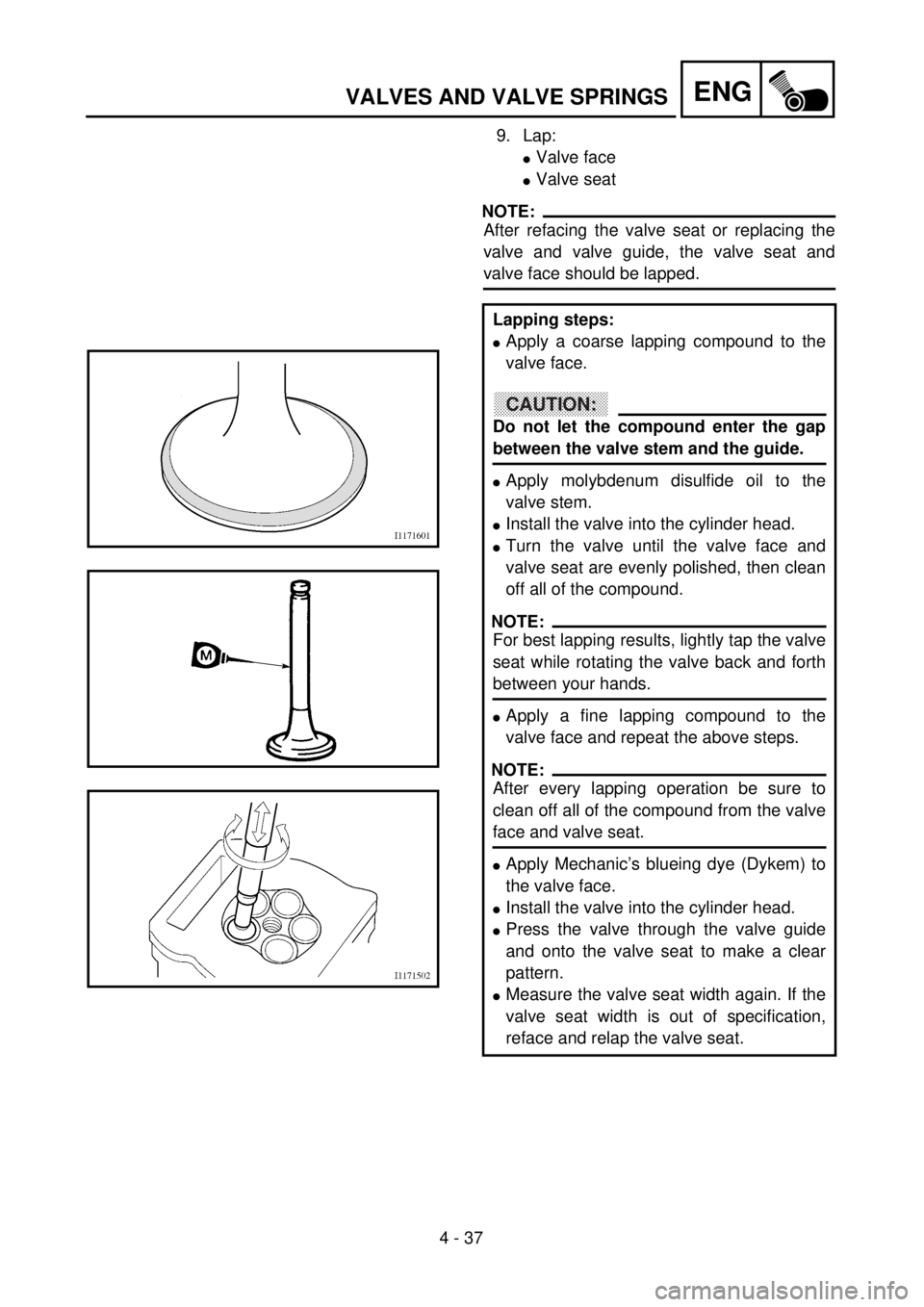
9. Lap:
lValve face
lValve seat
NOTE:
After refacing the valve seat or replacing the
valve and valve guide, the valve seat and
valve face should be lapped.
Lapping steps:
lApply a coarse lapping compound to the
valve face.
CAUTION:
Do not let the compound enter the gap
between the valve stem and the guide.
lApply molybdenum disulfide oil to the
valve stem.
lInstall the valve into the cylinder head.
lTurn the valve until the valve face and
valve seat are evenly polished, then clean
off all of the compound.
NOTE:
For best lapping results, lightly tap the valve
seat while rotating the valve back and forth
between your hands.
lApply a fine lapping compound to the
valve face and repeat the above steps.
NOTE:
After every lapping operation be sure to
clean off all of the compound from the valve
face and valve seat.
lApply Mechanic’s blueing dye (Dykem) to
the valve face.
lInstall the valve into the cylinder head.
lPress the valve through the valve guide
and onto the valve seat to make a clear
pattern.
lMeasure the valve seat width again. If the
valve seat width is out of specification,
reface and relap the valve seat.
Page 332 of 656
4 - 39
ENGVALVES AND VALVE SPRINGS
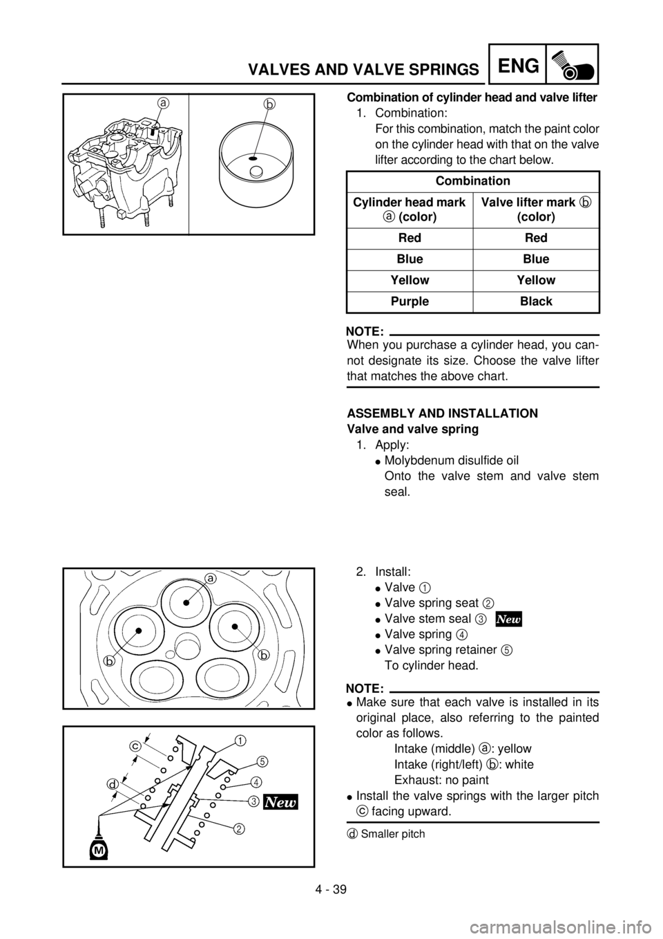
Combination of cylinder head and valve lifter
1. Combination:
For this combination, match the paint color
on the cylinder head with that on the valve
lifter according to the chart below.
NOTE:
When you purchase a cylinder head, you can-
not designate its size. Choose the valve lifter
that matches the above chart.Combination
Cylinder head mark
a (color)Valve lifter mark b
(color)
Red Red
Blue Blue
Yellow Yellow
Purple Black
ab
ASSEMBLY AND INSTALLATION
Valve and valve spring
1. Apply:
lMolybdenum disulfide oil
Onto the valve stem and valve stem
seal.
2. Install:
lValve 1
lValve spring seat 2
lValve stem seal 3
lValve spring 4
lValve spring retainer 5
To cylinder head.
NOTE:
lMake sure that each valve is installed in its
original place, also referring to the painted
color as follows.
Intake (middle) a: yellow
Intake (right/left) b: white
Exhaust: no paint
lInstall the valve springs with the larger pitch
c facing upward.
dSmaller pitch
Page 352 of 656
4 - 49
ENGCLUTCH
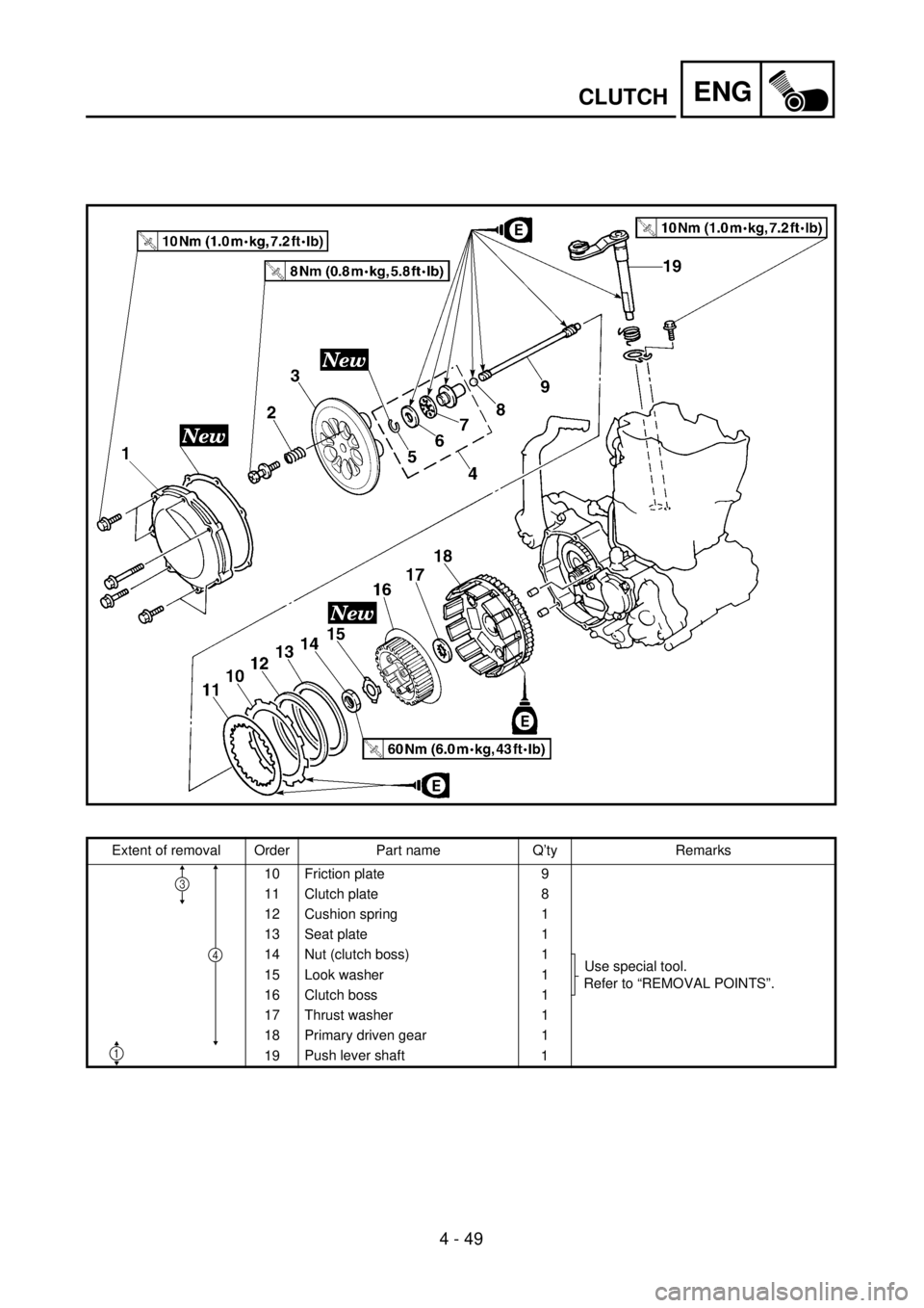
Extent of removal Order Part name Q’ty Remarks
10 Friction plate 9
11 Clutch plate 8
12 Cushion spring 1
13 Seat plate 1
14 Nut (clutch boss) 1
Use special tool.
Refer to “REMOVAL POINTS”. 15 Look washer 1
16 Clutch boss 1
17 Thrust washer 1
18 Primary driven gear 1
19Push lever shaft
1
4
1
3
Page 358 of 656
4 - 52
ENGCLUTCH
EC4A5000
ASSEMBLY AND INSTALLATION
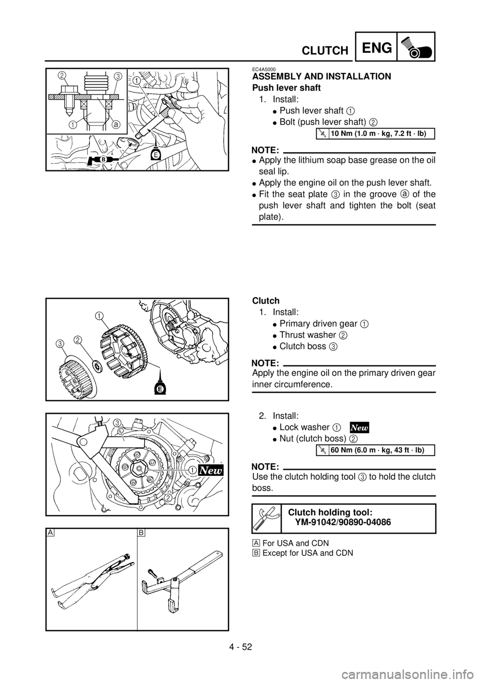
Push lever shaft
1. Install:
lPush lever shaft 1
lBolt (push lever shaft) 2
NOTE:
lApply the lithium soap base grease on the oil
seal lip.
lApply the engine oil on the push lever shaft.
lFit the seat plate 3 in the groove a of the
push lever shaft and tighten the bolt (seat
plate).
3
1
a2
T R..10 Nm (1.0 m · kg, 7.2 ft · lb)
Clutch
1. Install:
lPrimary driven gear 1
lThrust washer 2
lClutch boss 3
NOTE:
Apply the engine oil on the primary driven gear
inner circumference.
2. Install:
lLock washer 1
lNut (clutch boss) 2
NOTE:
Use the clutch holding tool 3 to hold the clutch
boss.
For USA and CDN
õExcept for USA and CDN
Clutch holding tool:
YM-91042/90890-04086
T R..60 Nm (6.0 m · kg, 43 ft · lb)
õ
Page 360 of 656
4 - 53
ENGCLUTCH
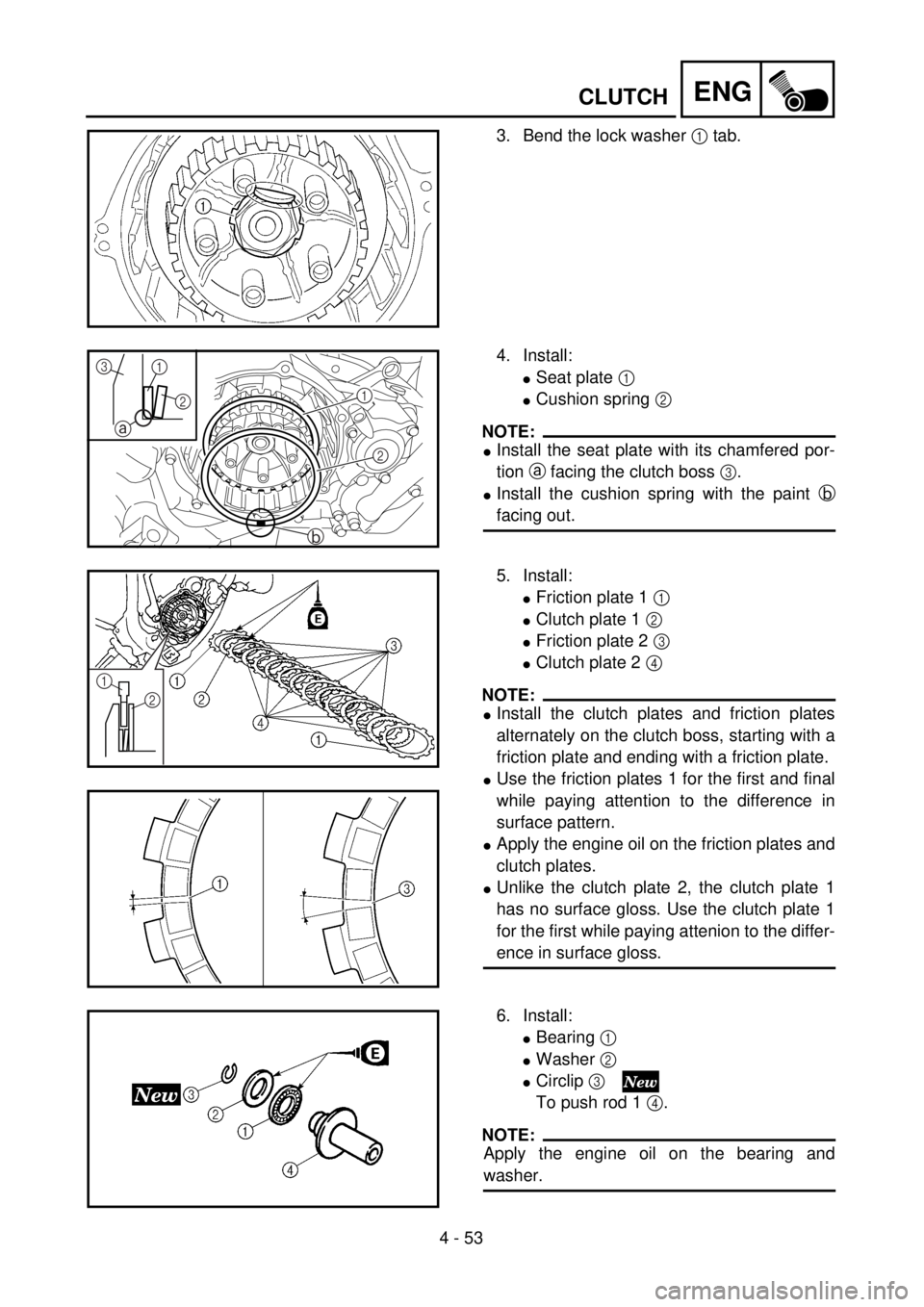
3. Bend the lock washer 1 tab.
4. Install:
lSeat plate 1
lCushion spring 2
NOTE:
lInstall the seat plate with its chamfered por-
tion a facing the clutch boss 3.
lInstall the cushion spring with the paint b
facing out.
1
2 1
2 3
a
b
5. Install:
lFriction plate 1 1
lClutch plate 1 2
lFriction plate 2 3
lClutch plate 2 4
NOTE:
lInstall the clutch plates and friction plates
alternately on the clutch boss, starting with a
friction plate and ending with a friction plate.
lUse the friction plates 1 for the first and final
while paying attention to the difference in
surface pattern.
lApply the engine oil on the friction plates and
clutch plates.
lUnlike the clutch plate 2, the clutch plate 1
has no surface gloss. Use the clutch plate 1
for the first while paying attenion to the differ-
ence in surface gloss.
1
2
6. Install:
lBearing 1
lWasher 2
lCirclip 3
To push rod 1 4.
NOTE:
Apply the engine oil on the bearing and
washer.
Page 408 of 656
4 - 77
ENGCDI MAGNETO
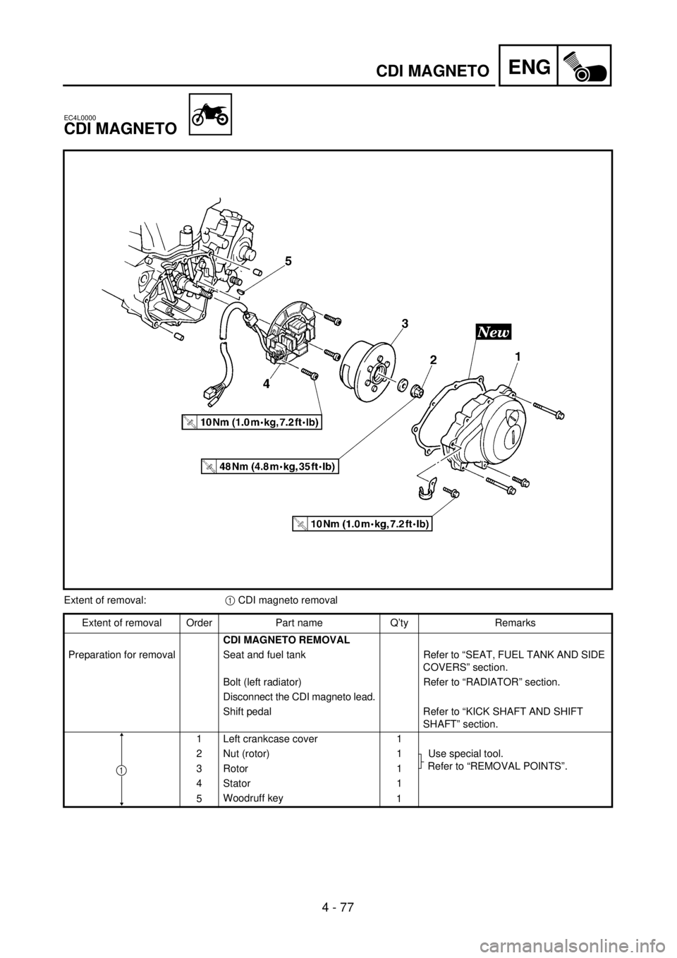
EC4L0000
CDI MAGNETO
Extent of removal:1 CDI magneto removal
Extent of removal Order Part name Q’ty Remarks
CDI MAGNETO REMOVAL
Preparation for removal Seat and fuel tank Refer to “SEAT, FUEL TANK AND SIDE
COVERS” section.
Bolt (left radiator) Refer to “RADIATOR” section.
Disconnect the CDI magneto lead.
Shift pedal Refer to “KICK SHAFT AND SHIFT
SHAFT” section.
1 Left crankcase cover 1
2 Nut (rotor) 1 Use special tool.
Refer to “REMOVAL POINTS”.
3 Rotor 1
4 Stator 1
5Woodruff key
1
1
Page 416 of 656
4 - 81
ENGENGINE REMOVAL
EC4M0000
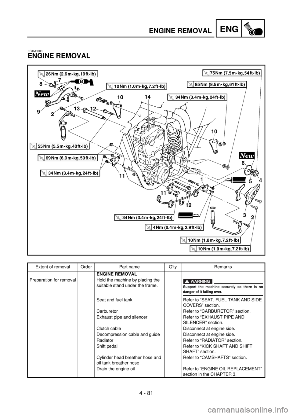
ENGINE REMOVAL
Extent of removal Order Part name Q’ty Remarks
ENGINE REMOVAL
Preparation for removal Hold the machine by placing the
suitable stand under the frame.
WARNING
Support the machine securely so there is nodanger of it falling over.
Seat and fuel tank Refer to “SEAT, FUEL TANK AND SIDE
COVERS” section.
Carburetor Refer to “CARBURETOR” section.
Exhaust pipe and silencer Refer to “EXHAUST PIPE AND
SILENCER” section.
Clutch cable Disconnect at engine side.
Decompression cable and guide Disconnect at engine side.
Radiator Refer to “RADIATOR” section.
Shift pedal Refer to “KICK SHAFT AND SHIFT
SHAFT” section.
Cylinder head breather hose and
oil tank breather hoseRefer to “CAMSHAFTS” section.
Drain the engine oil Refer to “ENGINE OIL REPLACEMENT”
section in the CHAPTER 3.
Page 518 of 656
5 - 33
CHASFRONT FORK
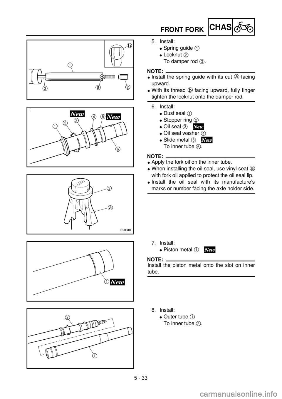
5. Install:
lSpring guide 1
lLocknut 2
To damper rod 3.
NOTE:
lInstall the spring guide with its cut a facing
upward.
lWith its thread b facing upward, fully finger
tighten the locknut onto the damper rod.
6. Install:
lDust seal 1
lStopper ring 2
lOil seal 3
lOil seal washer 4
lSlide metal 5
To inner tube 6.
NOTE:
lApply the fork oil on the inner tube.
lWhen installing the oil seal, use vinyl seat a
with fork oil applied to protect the oil seal lip.
lInstall the oil seal with its manufacture’s
marks or number facing the axle holder side.
7. Install:
lPiston metal 1
NOTE:
Install the piston metal onto the slot on inner
tube.
8. Install:
lOuter tube 1
To inner tube 2.
Page 566 of 656

5 - 57
CHASREAR SHOCK ABSORBER
EC580000
REAR SHOCK ABSORBER
Extent of removal:1 Rear shock absorber removal2 Rear shock absorber disassembly
Extent of removal Order Part name Q’ty Remarks
Preparation for removalREAR SHOCK ABSORBER
REMOVAL
Hold the machine by placing the
suitable stand under the engine.
WARNING
Support the machine securely so there is nodanger of it falling over.
Seat Refer to “SEAT, FUEL TANK AND SIDE
COVERS” section.
Silencer Refer to “EXHAUST PIPE AND
SILENCER” section in the CHAPTER 4.
1 Bolt (reservoir tank) 1
2 Clamp (air cleaner joint) 1 Only loosening.
3 Rear frame 1
4 Bolt (rear shock absorber-relay
arm)1 Hold the swingarm.
5 Bolt (rear shock absorber-frame) 1
6 Rear shock absorber 1
7 Locknut 1 Only loosening.
8 Adjuster 1 Only loosening.
9 Lower spring guide 1
1
2
Page 586 of 656
–+ELEC
6 - 3
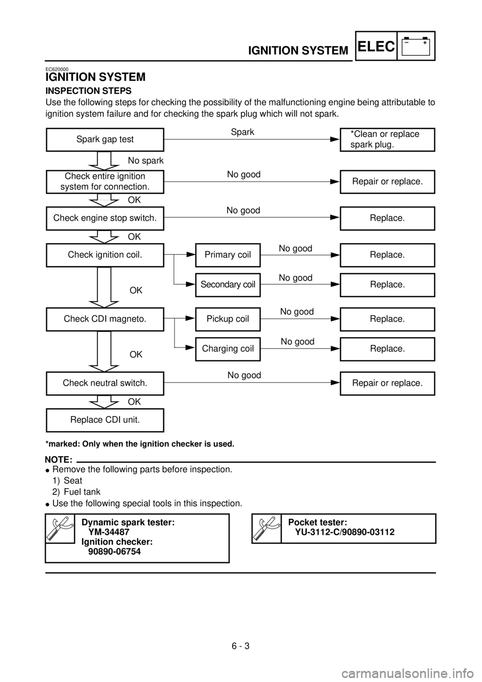
IGNITION SYSTEM
EC620000
IGNITION SYSTEM
INSPECTION STEPS
Use the following steps for checking the possibility of the malfunctioning engine being attributable to
ignition system failure and for checking the spark plug which will not spark.
*marked: Only when the ignition checker is used.
NOTE:
l
Remove the following parts before inspection.
1) Seat
2) Fuel tank
l
Use the following special tools in this inspection.
Dynamic spark tester:
YM-34487
Ignition checker:
90890-06754
Pocket tester:
YU-3112-C/90890-03112
Spark gap test*Clean or replace
spark plug.
Check entire ignition
system for connection.Repair or replace.
Check engine stop switch. Replace.
Check ignition coil. Primary coil Replace.
Secondary coil Replace.
Check CDI magneto. Pickup coil Replace.
Charging coil Replace.
Check neutral switch. Repair or replace.
Replace CDI unit.
No spark
OK
OK
OK
OK
OK
Spark
No good
No good
No good
No good
No good
No good
No good