YAMAHA YZ250F 2001 Repair Manual
Manufacturer: YAMAHA, Model Year: 2001, Model line: YZ250F, Model: YAMAHA YZ250F 2001Pages: 656, PDF Size: 24.86 MB
Page 61 of 656
GEN
INFO
MISE EN MARCHE ET RODAGE
ANLASSEN UND EINFAHREN
AVVIO E RODAGGIO
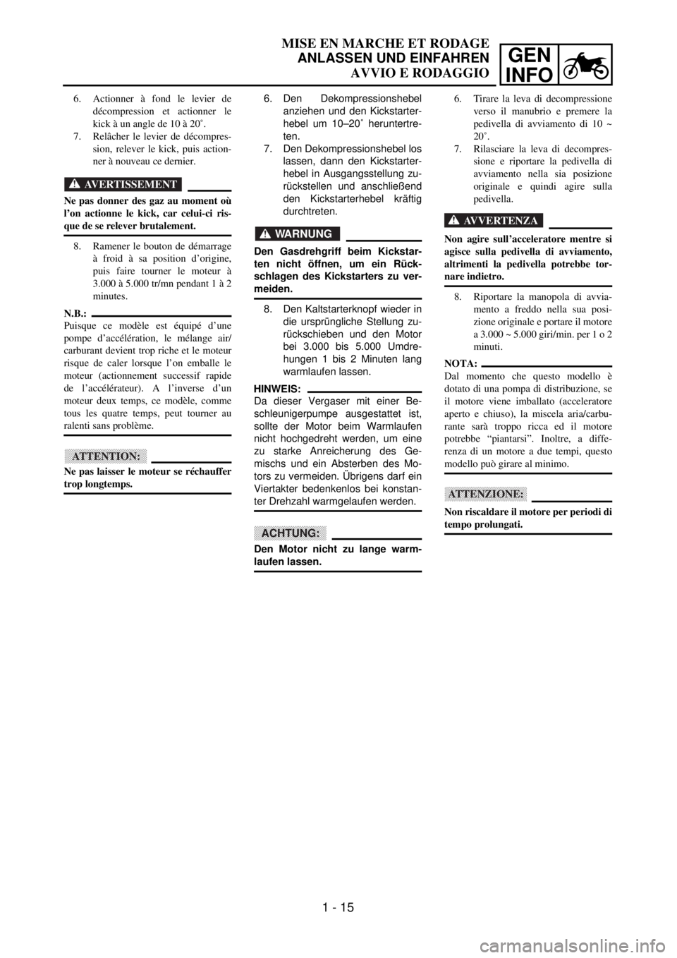
6. Den Dekompressionshebel
anziehen und den Kickstarter-
hebel um 10–20˚ heruntertre-
ten.
7. Den Dekompressionshebel los
lassen, dann den Kickstarter-
hebel in Ausgangsstellung zu-
rückstellen und anschließend
den Kickstarterhebel kräftig
durchtreten.
WARNUNG
Den Gasdrehgriff beim Kickstar-
ten nicht öffnen, um ein Rück-
schlagen des Kickstarters zu ver-
meiden.
8. Den Kaltstarterknopf wieder in
die ursprüngliche Stellung zu-
rückschieben und den Motor
bei 3.000 bis 5.000 Umdre-
hungen 1 bis 2 Minuten lang
warmlaufen lassen.
HINWEIS:
Da dieser Vergaser mit einer Be-
schleunigerpumpe ausgestattet ist,
sollte der Motor beim Warmlaufen
nicht hochgedreht werden, um eine
zu starke Anreicherung des Ge-
mischs und ein Absterben des Mo-
tors zu vermeiden. Übrigens darf ein
Viertakter bedenkenlos bei konstan-
ter Drehzahl warmgelaufen werden.
ACHTUNG:
Den Motor nicht zu lange warm-
laufen lassen. 6. Actionner à fond le levier de
décompression et actionner le
kick à un angle de 10 à 20˚.
7. Relâcher le levier de décompres-
sion, relever le kick, puis action-
ner à nouveau ce dernier.
AVERTISSEMENT
Ne pas donner des gaz au moment où
l’on actionne le kick, car celui-ci ris-
que de se relever brutalement.
8. Ramener le bouton de démarrage
à froid à sa position d’origine,
puis faire tourner le moteur à
3.000 à 5.000 tr/mn pendant 1 à 2
minutes.
N.B.:
Puisque ce modèle est équipé d’une
pompe d’accélération, le mélange air/
carburant devient trop riche et le moteur
risque de caler lorsque l’on emballe le
moteur (actionnement successif rapide
de l’accélérateur). A l’inverse d’un
moteur deux temps, ce modèle, comme
tous les quatre temps, peut tourner au
ralenti sans problème.
ATTENTION:
Ne pas laisser le moteur se réchauffer
trop longtemps.6. Tirare la leva di decompressione
verso il manubrio e premere la
pedivella di avviamento di 10 ~
20˚.
7. Rilasciare la leva di decompres-
sione e riportare la pedivella di
avviamento nella sia posizione
originale e quindi agire sulla
pedivella.
AVVERTENZA
Non agire sull’acceleratore mentre si
agisce sulla pedivella di avviamento,
altrimenti la pedivella potrebbe tor-
nare indietro.
8. Riportare la manopola di avvia-
mento a freddo nella sua posi-
zione originale e portare il motore
a 3.000 ~ 5.000 giri/min. per 1 o 2
minuti.
NOTA:
Dal momento che questo modello è
dotato di una pompa di distribuzione, se
il motore viene imballato (acceleratore
aperto e chiuso), la miscela aria/carbu-
rante sarà troppo ricca ed il motore
potrebbe “piantarsi”. Inoltre, a diffe-
renza di un motore a due tempi, questo
modello può girare al minimo.
ATTENZIONE:
Non riscaldare il motore per periodi di
tempo prolungati.
1 - 15
Page 62 of 656
1 - 16
GEN
INFO
STARTING AND BREAK-IN
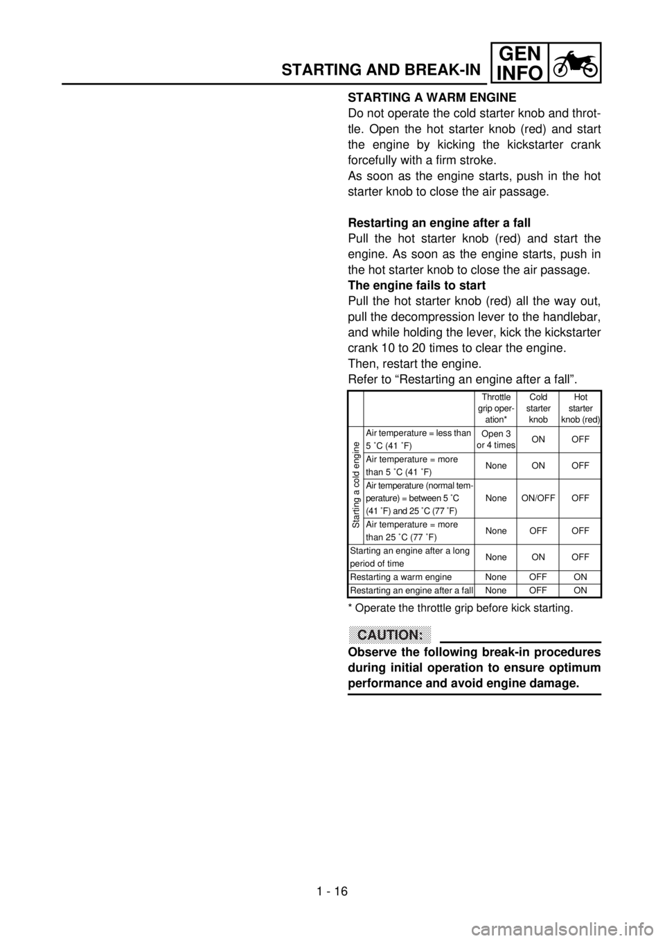
STARTING A WARM ENGINE
Do not operate the cold starter knob and throt-
tle. Open the hot starter knob (red) and start
the engine by kicking the kickstarter crank
forcefully with a firm stroke.
As soon as the engine starts, push in the hot
starter knob to close the air passage.
Restarting an engine after a fall
Pull the hot starter knob (red) and start the
engine. As soon as the engine starts, push in
the hot starter knob to close the air passage.
The engine fails to start
Pull the hot starter knob (red) all the way out,
pull the decompression lever to the handlebar,
and while holding the lever, kick the kickstarter
crank 10 to 20 times to clear the engine.
Then, restart the engine.
Refer to “Restarting an engine after a fall”.
* Operate the throttle grip before kick starting.
CAUTION:
Observe the following break-in procedures
during initial operation to ensure optimum
performance and avoid engine damage.
Throttle
grip oper-
ation*Cold
starter
knobHot
starter
knob (red)
Starting a cold engine
Air temperature = less than
5 ˚C (41 ˚F)Open 3
or 4 timesON OFF
Air temperature = more
than 5 ˚C (41 ˚F)None ON OFF
Air temperature (normal tem-
perature) = between 5 ˚C
(41 ˚F) and 25 ˚C (77 ˚F)None ON/OFF OFF
Air temperature = more
than 25 ˚C (77 ˚F)None OFF OFF
Starting an engine after a long
period of timeNone ON OFF
Restarting a warm engine None OFF ON
Restarting an engine after a fall None OFF ON
Page 63 of 656
GEN
INFO
MISE EN MARCHE ET RODAGE
ANLASSEN UND EINFAHREN
AVVIO E RODAGGIO
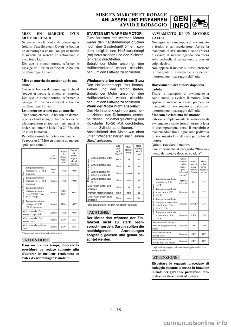
STARTEN MIT WARMEM MOTOR
Zum Anlassen des warmen Motors
weder den Kaltstarterknopf drücken
noch den Gasdrehgriff öffnen, son-
dern lediglich den Heißstarterknopf
(rot) herausziehen und den Kickstar-
ter kräftig durchtreten.
Sobald der Motor anspringt, den
Heißstarterknopf wieder einschie-
ben, um den Luftweg zu schließen.
Wiederanstarten nach einem Sturz
Den Heißstarterknopf (rot) heraus-
ziehen und den Motor starten.
Sobald der Motor anspringt, den
Heißstarterknopf wieder einschie-
ben, um den Luftweg zu schließen.
Wenn der Motor nicht anspringt
Den Heißstarterknopf (rot) ganz her-
ausziehen, den Dekompressionshe-
bel ziehen und dabei gleichzeitig den
Kickstarter 10–20 Mal durchtreten,
um den Zylinder zu entleeren.
Anschließend den Motor wie oben
unter “Wiederanstarten nach einem
Sturz” anlassen.
ACHTUNG:
Der Motor darf während der Ein-
fahrzeit nicht zu stark bean-
sprucht werden. Darum sollten die
nachfolgenden Anweisungen
sorgfältig gelesen und genau be-
achtet werden.
Gas-
dreh-
griff
öffnen*Kalt-
starter-
knopfHeiß-
starter-
knopf
(rot)
Lufttemperatur unter
5 ˚C3–4 ´Ja nein
Lufttemperatur über
5 ˚CNein Ja nein
Lufttemperatur zwi-
schen 5 und 25 ˚CNein Ja/nein nein
Lufttemperatur über
25 ˚CNein nein nein
Motor nach langer Zeit
anlassenNein Ja nein
Warmen Motor anlassen Nein nein Ja
Motor nach einem Sturz
anlassenNein nein Ja
* Den Gasdrehgriff vor dem Kickstarten betätigen
Kalten Motor anlassen
MISE EN MARCHE D’UN
MOTEUR CHAUD
Ne pas activer le bouton de démarrage a
froid ni l’accélérateur. Ouvrir le bouton
de démarrage à chaud (rouge) et mettre
le moteur en marche en actionnant le
avec force kick.
Dès que le moteur tourne, refermer le
passage de l’air en enfonçant le bouton
de démarrage à chaud.
Mise en marche du moteur après une
chute
Ouvrir le bouton de démarrage à chaud
(rouge) et mettre le moteur en marche.
Dès que le moteur tourne, refermer le
passage de l’air en enfonçant le bouton
de démarrage à chaud.
Le moteur ne se met pas en marche
Tirer complètement le bouton de démar-
rage à chaud (rouge), tirer le levier de
décompression et tout en maintenant le
levier, actionner le kick 10 à 20 fois afin
de vider le moteur.
Remettre ensuite le moteur en marche.
Se reporter à “Mise en marche du moteur
après une chute”.
* Donner des gaz avant d’actionner le kick.
ATTENTION:
Dans un premier temps, observer la
procédure de rodage suivante afin
d’assurer le meilleur rendement et
éviter d’endommager le moteur.
Gaz
donnés*Bouton
de
démar-
rage à
froid Bouton
de
démar-
rage à
chaud
(rouge)
Température atmos-
phérique = 5 ˚C (41 ˚F)
maximum3 ou 4
foisOUI NON
Température atmos-
phérique = 5 ˚C (41 ˚F)
minimumAucun OUI NON
Température atmos-
phérique normale =
entre 5˚C (41 ˚F) et
25 ˚C (77 ˚F)AucunOUI/
NONNON
Température atmos-
phérique = 25 ˚C
(77 ˚F) minimumAucun NON NON
Mise en marche d’un
moteur presque froidAucun OUI NON
Mise en marche d’un
moteur chaudAucun NON OUI
Mise en marche après une
chuteAucun NON OUI
Mise en marche d’un moteur froid
AVVIAMENTO DI UN MOTORE
CALDO
Non agire sulla manopola di avviamento
a freddo e sull’acceleratore. Aprire la
manopola di avviamento a caldo (rossa)
e avviare il motore agendo con forza
sulla pedivella di avviamento e con un
colpo deciso.
Non appena il motore si avvia, premere
la manopola di avviamento a caldo per
interrompere il passaggio dell’aria.
Riavviamento del motore dopo una
caduta
Tirare la manopola di avviamento a
caldo (rossa) e avviare il motore. Non
appena il motore si avvia, premere la
manopola di avviamento a caldo per
interrompere il passaggio dell’aria.
Mancato avviamento del motore
Estrarre completamente la manopola di
avviamento a caldo (rossa), tirare la leva
di decompressione verso il manubrio e
mantenendola tirata, agire sulla pedivella
di avviamento 10 - 20 volte per pulire il
motore.
Quindi, riavviare il motore.
Fare riferimento al paragrafo “Riavvia-
mento del motore dopo una caduta”.
* Agire sulla manopola dell’acceleratore prima dell’avvia-
mento a pedale.
ATTENZIONE:
Rispettare le seguenti procedure di
rodaggio durante la messa in funzione
iniziale per garantire prestazioni otti-
mali ed evitare danni al motore.
Funzio-
namento
della
mano-
pola
dell’accel
eratore*Mano-
pola di
avvia-
mento a
freddoMano-
pola di
avvia-
mento a
caldo
Temperatura dell’aria
= inferiore a 5 ˚C
(41 ˚F)Aprire 3
o 4 volteON OFF
Temperatura dell’aria
= superiore a 5 ˚C
(41 ˚F)Nessuno ON OFF
Temperatura dell’aria
(temperatura normale)
= tra 5 ˚C (41 ˚F) e
25 ˚C (77 ˚F)Nessuno ON/OFF OFF
Temperatura dell’aria
= superiore a 25 ˚C
(77 ˚F)Nessuno OFF OFF
Avviamento del motore
dopo un lungo periodo di
tempoNessuno ON OFF
Riavviamento di un
motore caldoNessuno OFF ON
Riavviamento di un
motore dopo una cadutaNessuno OFF ON
Avviamento di un motore freddo
1 - 16
Page 64 of 656

1 - 17
GEN
INFO
BREAK-IN PROCEDURES
1. Before starting the engine, fill the fuel
tank with the fuel.
2. Perform the pre-operation checks on the
machine.
3. Start and warm up the engine. Check the
idle speed, and check the operation of
the controls and the engine stop switch.
Then, restart the engine and check its
operation within no more than 5 minutes
after it is restarted.
4. Operate the machine in the lower gears
at moderate throttle openings for five to
eight minutes.
5. Check how the engine runs when the
motorcycle is ridden with the throttle 1/4
to 1/2 open (low to medium speed) for
about one hour.
6. Restart the engine and check the opera-
tion of the machine throughout its entire
operating range. Restart the machine
and operate it for about 10 to 15 more
minutes. The machine will now be ready
to race.
CAUTION:
lAfter the break-in or before each race,
you must check the entire machine for
loose fittings and fasteners as per
“TORQUE-CHECK POINTS”.
Tighten all such fasteners as required.
lWhen any of the following parts have
been replaced, they must be broken in.
CYLINDER AND CRANKSHAFT:
About one hour of break-in operation is
necessary.
PISTON, RING, VALVES, CAMSHAFTS
AND GEARS:
These parts require about 30 minutes of
break-in operation at half-throttle or less.
Observe the condition of the engine care-
fully during operation.
STARTING AND BREAK-IN
Page 65 of 656
GEN
INFO
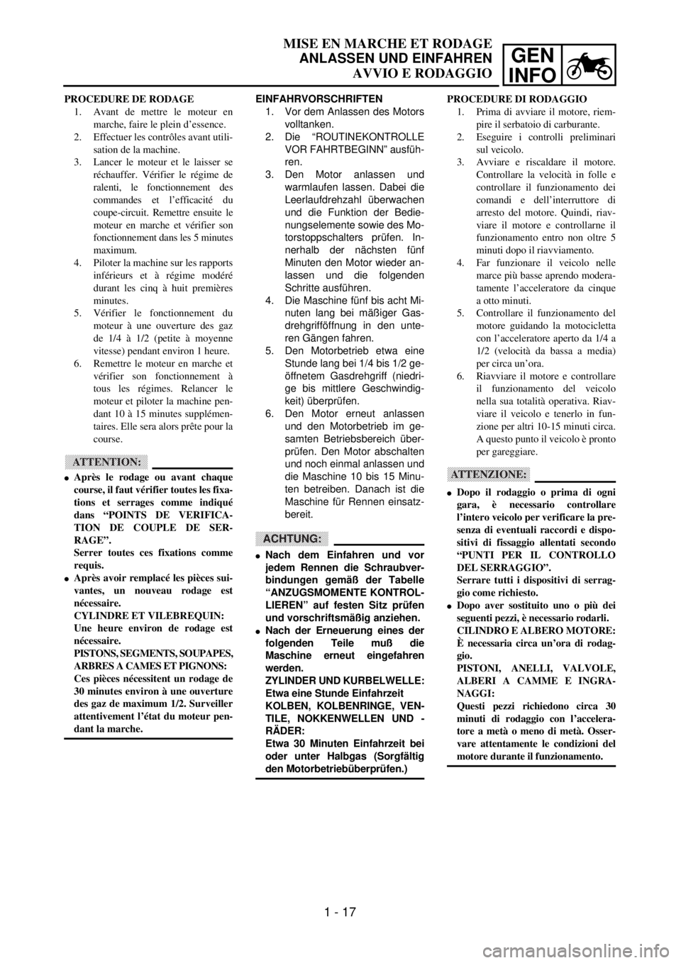
EINFAHRVORSCHRIFTEN
1. Vor dem Anlassen des Motors
volltanken.
2. Die “ROUTINEKONTROLLE
VOR FAHRTBEGINN” ausfüh-
ren.
3. Den Motor anlassen und
warmlaufen lassen. Dabei die
Leerlaufdrehzahl überwachen
und die Funktion der Bedie-
nungselemente sowie des Mo-
torstoppschalters prüfen. In-
nerhalb der nächsten fünf
Minuten den Motor wieder an-
lassen und die folgenden
Schritte ausführen.
4. Die Maschine fünf bis acht Mi-
nuten lang bei mäßiger Gas-
drehgrifföffnung in den unte-
ren Gängen fahren.
5. Den Motorbetrieb etwa eine
Stunde lang bei 1/4 bis 1/2 ge-
öffnetem Gasdrehgriff (niedri-
ge bis mittlere Geschwindig-
keit) überprüfen.
6. Den Motor erneut anlassen
und den Motorbetrieb im ge-
samten Betriebsbereich über-
prüfen. Den Motor abschalten
und noch einmal anlassen und
die Maschine 10 bis 15 Minu-
ten betreiben. Danach ist die
Maschine für Rennen einsatz-
bereit.
ACHTUNG:
lNach dem Einfahren und vor
jedem Rennen die Schraubver-
bindungen gemäß der Tabelle
“ANZUGSMOMENTE KONTROL-
LIEREN” auf festen Sitz prüfen
und vorschriftsmäßig anziehen.
lNach der Erneuerung eines der
folgenden Teile muß die
Maschine erneut eingefahren
werden.
ZYLINDER UND KURBELWELLE:
Etwa eine Stunde Einfahrzeit
KOLBEN, KOLBENRINGE, VEN-
TILE, NOKKENWELLEN UND -
RÄDER:
Etwa 30 Minuten Einfahrzeit bei
oder unter Halbgas (Sorgfältig
den Motorbetriebüberprüfen.)
MISE EN MARCHE ET RODAGE
ANLASSEN UND EINFAHREN
AVVIO E RODAGGIO
PROCEDURE DE RODAGE
1. Avant de mettre le moteur en
marche, faire le plein d’essence.
2. Effectuer les contrôles avant utili-
sation de la machine.
3. Lancer le moteur et le laisser se
réchauffer. Vérifier le régime de
ralenti, le fonctionnement des
commandes et l’efficacité du
coupe-circuit. Remettre ensuite le
moteur en marche et vérifier son
fonctionnement dans les 5 minutes
maximum.
4. Piloter la machine sur les rapports
inférieurs et à régime modéré
durant les cinq à huit premières
minutes.
5. Vérifier le fonctionnement du
moteur à une ouverture des gaz
de 1/4 à 1/2 (petite à moyenne
vitesse) pendant environ 1 heure.
6. Remettre le moteur en marche et
vérifier son fonctionnement à
tous les régimes. Relancer le
moteur et piloter la machine pen-
dant 10 à 15 minutes supplémen-
taires. Elle sera alors prête pour la
course.
ATTENTION:
lAprès le rodage ou avant chaque
course, il faut vérifier toutes les fixa-
tions et serrages comme indiqué
dans “POINTS DE VERIFICA-
TION DE COUPLE DE SER-
RAGE”.
Serrer toutes ces fixations comme
requis.
lAprès avoir remplacé les pièces sui-
vantes, un nouveau rodage est
nécessaire.
CYLINDRE ET VILEBREQUIN:
Une heure environ de rodage est
nécessaire.
PISTONS, SEGMENTS, SOUPAPES,
ARBRES A CAMES ET PIGNONS:
Ces pièces nécessitent un rodage de
30 minutes environ à une ouverture
des gaz de maximum 1/2. Surveiller
attentivement l’état du moteur pen-
dant la marche.PROCEDURE DI RODAGGIO
1. Prima di avviare il motore, riem-
pire il serbatoio di carburante.
2. Eseguire i controlli preliminari
sul veicolo.
3. Avviare e riscaldare il motore.
Controllare la velocità in folle e
controllare il funzionamento dei
comandi e dell’interruttore di
arresto del motore. Quindi, riav-
viare il motore e controllarne il
funzionamento entro non oltre 5
minuti dopo il riavviamento.
4. Far funzionare il veicolo nelle
marce più basse aprendo modera-
tamente l’acceleratore da cinque
a otto minuti.
5. Controllare il funzionamento del
motore guidando la motocicletta
con l’acceleratore aperto da 1/4 a
1/2 (velocità da bassa a media)
per circa un’ora.
6. Riavviare il motore e controllare
il funzionamento del veicolo
nella sua totalità operativa. Riav-
viare il veicolo e tenerlo in fun-
zione per altri 10-15 minuti circa.
A questo punto il veicolo è pronto
per gareggiare.
ATTENZIONE:
lDopo il rodaggio o prima di ogni
gara, è necessario controllare
l’intero veicolo per verificare la pre-
senza di eventuali raccordi e dispo-
sitivi di fissaggio allentati secondo
“PUNTI PER IL CONTROLLO
DEL SERRAGGIO”.
Serrare tutti i dispositivi di serrag-
gio come richiesto.
lDopo aver sostituito uno o più dei
seguenti pezzi, è necessario rodarli.
CILINDRO E ALBERO MOTORE:
È necessaria circa un’ora di rodag-
gio.
PISTONI, ANELLI, VALVOLE,
ALBERI A CAMME E INGRA-
NAGGI:
Questi pezzi richiedono circa 30
minuti di rodaggio con l’accelera-
tore a metà o meno di metà. Osser-
vare attentamente le condizioni del
motore durante il funzionamento.
1 - 17
Page 66 of 656

GEN
INFO
1 - 18
TORQUE-CHECK POINTS
TORQUE-CHECK POINTS
Frame construction
Combined seat and fuel tank
Exhaust system
Engine mounting
Steering Steering stem to
handlebar
Suspension Front Steering stem to front
fork
Rear For link type
Rear Installation of rear
shock absorber
Rear Installation of swing-
arm
Wheel Installation of wheel Front
Rear
Brake Front
Rear
Fuel systemFrame to rear frame
Fuel tank to frame
Silencer to rear frame
Frame to engine
Steering stem to frame
Steering stem to upper bracket
Upper bracket to handlebar
Front fork to upper bracket
Front fork to lower bracket
Assembly of links
Link to frame
Link to rear shock absorber
Link to swingarm
Rear shock absorber to frame
Tightening of pivot shaft
Tightening of wheel axle
Tightening of axle holder
Tightening of wheel axle
Wheel to rear wheel sprocket
Brake caliper to front fork
Brake disc to wheel
Tightening of union bolt
Brake master cylinder to handlebar
Tightening of bleed screw
Brake disc to wheel
Tightening of union bolt
Brake master cylinder to frame
Tightening of bleed screw
Fuel tank to fuel cock
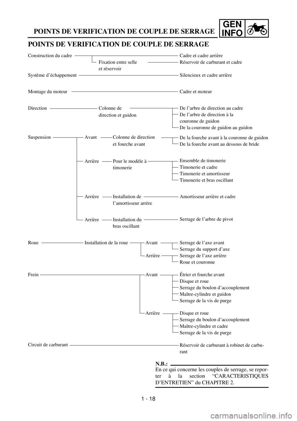
NOTE:
Concerning the tightening torque, refer to
“MAINTENANCE SPECIFICATIONS” section
in the CHAPTER 2.
Page 67 of 656
GEN
INFO
POINTS DE VERIFICATION DE COUPLE DE SERRAGE
POINTS DE VERIFICATION DE COUPLE DE SERRAGE
Construction du cadre
Fixation entre selle
et réservoir
Système d’échappement
Montage du moteur
Direction Colonne de
direction et guidon
Suspension Avant Colonne de direction
et fourche avant
Arrière Pour le modèle à
timonerie
Arrière Installation de
l’amortisseur arrère
Arrière Installation du
bras oscillant
Roue Installation de la roue Avant
Arrière
Frein Avant
Arrière
Circuit de carburantCadre et cadre arrière
Réservoir de carburant et cadre
Silencieux et cadre arrière
Cadre et moteur
De l’arbre de direction au cadre
De l’arbre de direction à la
couronne de guidon
De la couronne de guidon au guidon
De la fourche avant à la couronne de guidon
De la fourche avant au dessous de bride
Ensemble de timonerie
Timonerie et cadre
Timonerie et amortisseur
Timonerie et bras oscillant
Amortisseur arrière et cadre
Serrage de l’arbre de pivot
Serrage de l’axe avant
Serrage du support d’axe
Serrage de l’axe arrière
Roue et couronne
Étrier et fourche avant
Disque et roue
Serrage du boulon d’accouplement
Maître-cylindre et guidon
Serrage de la vis de purge
Disque et roue
Serrage du boulon d’accouplement
Maître-cylindre et cadre
Serrage de la vis de purge
Réservoir de carburant à robinet de carbu-
rant
N.B.:
En ce qui concerne les couples de serrage, se repor-
ter à la section “CARACTERISTIQUES
D’ENTRETIEN” du CHAPITRE 2.
1 - 18
Page 68 of 656
GEN
INFO
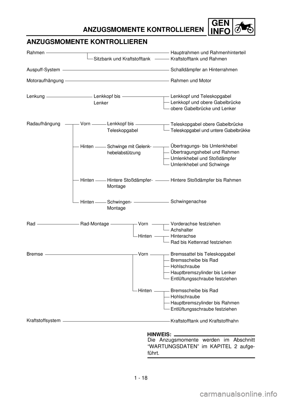
ANZUGSMOMENTE KONTROLLIEREN
ANZUGSMOMENTE KONTROLLIEREN
Rahmen
Sitzbank und Kraftstofftank
Auspuff-System
Motoraufhängung
Lenkung Lenkkopf bis
Lenker
Radaufhängung Vorn Lenkkopf bis
Teleskopgabel
Hinten Schwinge mit Gelenk-
hebelabstützung
Hinten Hintere Stoßdämpfer-
Montage
Hinten Schwingen-
Montage
Rad Rad-Montage Vorn
Hinten
Bremse Vorn
Hinten
KraftstoffsystemHauptrahmen und Rahmenhinterteil
Kraftstofftank und Rahmen
Schalldämpfer an Hinterrahmen
Rahmen und Motor
Lenkkopf und Teleskopgabel
Lenkkopf und obere Gabelbrücke
obere Gabelbrücke und Lenker
Teleskopgabel obere Gabelbrücke
Teleskopgabel und untere Gabelbrükke
Übertragungs- bis Umlenkhebel
Übertragungshebel und Rahmen
Umlenkhebel und Stoßdämpfer
Umlenkhebel und Schwinge
Hintere Stoßdämpfer bis Rahmen
Schwingenachse
Vorderachse festziehen
Achshalter
Hinterachse
Rad bis Kettenrad festziehen
Bremssattel bis Teleskopgabel
Bremsscheibe bis Rad
Hohlschraube
Hauptbremszylinder bis Lenker
Entlüftungsschraube festziehen
Bremsscheibe bis Rad
Hohlschraube
Hauptbremszylinder bis Rahmen
Entlüftungsschraube festziehen
Kraftstofftank und Kraftstoffhahn
HINWEIS:
Die Anzugsmomente werden im Abschnitt
“WARTUNGSDATEN” im KAPITEL 2 aufge-
führt.
1 - 18
Page 69 of 656

GEN
INFO
PUNTI PER IL CONTROLLO DEL SERRAGGIO
PUNTI PER IL CONTROLLO DEL SERRAGGIO
Struttura del telaio
Sella e serbatoio del
carburante combinati
Sistema di scarico
Supporto motore
Sterzo Cannotto di sterzo al
manubrio
Sospensione Anteriore Cannotto di sterzo alla
forcella anteriore
Posteriore Per tipo di braccio
Posteriore Installazione
ammortizzatore
posteriore
Posteriore Installazione forcellone
oscillante
Ruota Installazione ruota Anteriore
Posteriore
Freno Anteriore
Posteriore
Sistema di alimentazioneTelaio al telaio posteriore
Serbatoio del carburante al telaio
Marmitta di scarico al telaio posteriore
Telaio al motore
Cannotto di sterzo al telaio
Cannotto di sterzo alla trave superiore
Trave superiore al manubrio
Forcella anteriore alla trave superiore
Forcella anteriore alla trave inferiore
Gruppo bracci
Braccio al telaio
Braccio all’ammortizzatore posteriore
Braccio al forcellone oscillante
Ammortizzatore posteriore al telaio
Serraggio del perno
Serraggio dell’asse della ruota
Serraggio del supporto dell’asse
Serraggio dell’asse della ruota
Ruota alla corona della ruota posteriore
Pinza del freno alla forcella anteriore
Disco del freno alla ruota
Serraggio della vite di unione
Cilindro al manubrio
Serraggio della valvolina di spurgo
Disco del freno alla ruota
Serraggio della vite di unione
Cilindro al telaio
Serraggio della valvolina di spurgo
Serbatoio del carburante al rubinetto del
carburante
NOTA:
In relazione alla coppia di serraggio, fare riferi-
mento al paragrafo “SPECIFICHE DI MANU-
TENZIONE” al CAPITOLO 2.
1 - 18
Page 70 of 656

1 - 19
GEN
INFO
CLEANING AND STORAGE
EC1B0000
CLEANING AND STORAGE
EC1B1000
CLEANING
Frequent cleaning of your machine will
enhance its appearance, maintain good over-
all performance, and extend the life of many
components.
1. Before washing the machine, block off
the end of the exhaust pipe to prevent
water from entering. A plastic bag
secured with a rubber band may be used
for this purpose.
2. If the engine is excessively greasy, apply
some degreaser to it with a paint brush.
Do not apply degreaser to the chain,
sprockets, or wheel axles.
3. Rinse the dirt and degreaser off with a
garden hose; use only enough pressure
to do the job.
CAUTION:
Excessive hose pressure may cause water
seepage and contamination of wheel bear-
ings, front forks, brakes and transmission
seals. Many expensive repair bills have
resulted from improper high pressure
detergent applications such as those avail-
able in coin-operated car washers.
4. After the majority of the dirt has been
hosed off, wash all surfaces with warm
water and a mild detergent. Use an old
toothbrush to clean hard-to-reach places.
5. Rinse the machine off immediately with
clean water, and dry all surfaces with a
soft towel or cloth.
6. Immediately after washing, remove
excess water from the chain with a paper
towel and lubricate the chain to prevent
rust.
7. Clean the seat with a vinyl upholstery
cleaner to keep the cover pliable and
glossy.
8. Automotive wax may be applied to all
painted or chromed surfaces. Avoid com-
bination cleaner-waxes, as they may con-
tain abrasives.
9. After completing the above, start the
engine and allow it to idle for several min-
utes.