maintenance YAMAHA YZ250F 2002 Manuale duso (in Italian)
[x] Cancel search | Manufacturer: YAMAHA, Model Year: 2002, Model line: YZ250F, Model: YAMAHA YZ250F 2002Pages: 666, PDF Dimensioni: 39.45 MB
Page 4 of 666
EC020000
INTRODUCTION
Congratulations on your purchase of a
Yamaha YZ series. This model is the culmina-
tion of Yamaha’s vast experience in the pro-
duction of pacesetting racing machines. It
represents the highest grade of craftsmanship
and reliability that have made Yamaha a
leader.
This manual explains operation, inspection,
basic maintenance and tuning of your
machine. If you have any questions about this
manual or your machine, please contact your
Yamaha dealer.
NOTE:
As improvements are made on this model,
some data in this manual may become out-
dated. If you have any questions, please con-
sult your Yamaha dealer.
WARNING
PLEASE READ THIS MANUAL CAREFULLY
AND COMPLETELY BEFORE OPERATING
THIS MACHINE. DO NOT ATTEMPT TO
OPERATE THIS MACHINE UNTIL YOU
HAVE ATTAINED A SATISFACTORY
KNOWLEDGE OF ITS CONTROLS AND
OPERATING FEATURES AND UNTIL YOU
HAVE BEEN TRAINED IN SAFE AND
PROPER RIDING TECHNIQUES. REGULAR
INSPECTIONS AND CAREFUL MAINTE-
NANCE, ALONG WITH GOOD RIDING
SKILLS, WILL ENSURE THAT YOU SAFETY
ENJOY THE CAPABILITIES AND THE RELI-
ABILITY OF THIS MACHINE.
Page 10 of 666
EC050000
TO THE NEW OWNER
This manual will provide you with a good basic
understanding of features, operation, and
basic maintenance and inspection items of this
machine. Please read this manual carefully
and completely before operating your new
machine. If you have any questions regarding
the operation or maintenance of your machine,
please consult your Yamaha dealer.
NOTE:
This manual should be considered a perma-
nent part of this machine and should remain
with it even if the machine is subsequently
sold.
EC060000
NOTICE
Some data in this manual may become out-
dated due to improvements made to this
model in the future. If there is any question
you have regarding this manual or your
machine, please consult your Yamaha
dealer.
EC070001
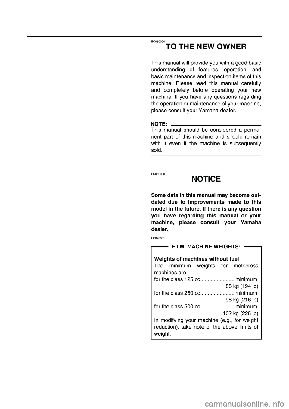
F.I.M. MACHINE WEIGHTS:
Weights of machines without fuel
The minimum weights for motocross
machines are:
for the class 125 cc....................... minimum
88 kg (194 lb)
for the class 250 cc....................... minimum
98 kg (216 lb)
for the class 500 cc....................... minimum
102 kg (225 lb)
In modifying your machine (e.g., for weight
reduction), take note of the above limits of
weight.
Page 20 of 666

EC0A0000
CONTENTS
CHAPTER 1
GENERAL INFORMATION
DESCRIPTION
.......................................... 1-1
MACHINE IDENTIFICATION
.................... 1-2
IMPORTANT INFORMATION
................... 1-3
CHECKING OF CONNECTION
................ 1-6
SPECIAL TOOLS
...................................... 1-7
CONTROL FUNCTIONS
......................... 1-10
FUEL
....................................................... 1-14
STARTING AND BREAK-IN
................... 1-15
TORQUE-CHECK POINTS
..................... 1-19
CLEANING AND STORAGE
.................. 1-20
CHAPTER 2
SPECIFICATIONS
GENERAL SPECIFICATIONS
.................. 2-1
MAINTENANCE SPECIFICATIONS
......... 2-4
GENERAL TORQUE
SPECIFICATIONS
.................................. 2-17
DEFINITION OF UNITS
.......................... 2-17
CABLE ROUTING DIAGRAM
................ 2-18
CHAPTER 3
REGULAR INSPECTION AND
ADJUSTMENTS
MAINTENANCE INTERVALS
................... 3-1
PRE-OPERATION INSPECTION
AND MAINTENANCE
............................... 3-4
ENGINE
..................................................... 3-5
CHASSIS
................................................. 3-25
ELECTRICAL
.......................................... 3-46
Page 68 of 666

GEN
INFO
1 - 19
TORQUE-CHECK POINTS
TORQUE-CHECK POINTS
Frame construction
Combined seat and fuel tank
Exhaust system
Engine mounting
Steering Steering stem to
handlebar
Suspension Front Steering stem to front
fork
Rear For link type
Rear Installation of rear
shock absorber
Rear Installation of swing-
arm
Wheel Installation of wheel Front
Rear
Brake Front
Rear
Fuel systemFrame to rear frame
Fuel tank to frame
Silencer to rear frame
Frame to engine
Engine bracket to engine
Engine bracket to frame
Steering stem to frame
Steering stem to upper bracket
Upper bracket to handlebar
Front fork to upper bracket
Front fork to lower bracket
Assembly of links
Link to frame
Link to rear shock absorber
Link to swingarm
Rear shock absorber to frame
Tightening of pivot shaft
Tightening of wheel axle
Tightening of axle holder
Tightening of wheel axle
Wheel to rear wheel sprocket
Brake caliper to front fork
Brake disc to wheel
Tightening of union bolt
Brake master cylinder to handlebar
Tightening of bleed screw
Brake pedal to frame
Brake disc to wheel
Tightening of union bolt
Brake master cylinder to frame
Tightening of bleed screw
Fuel tank to fuel cock
NOTE:
Concerning the tightening torque, refer to
“MAINTENANCE SPECIFICATIONS” section
in the CHAPTER 2.
Page 79 of 666

SPEC
2 - 4
MAINTENANCE SPECIFICATIONS
MAINTENANCE SPECIFICATIONS
ENGINE
Item Standard Limit
Cylinder head:
Warp limit ---- 0.05 mm
(0.002 in)
Cylinder:
Bore size 77.00 ~ 77.01 mm
(3.0315 ~ 3.0319 in)----
Out of round limit ---- 0.05 mm
(0.002 in)
Camshaft:
Drive method Chain drive (Left) ----
Camshaft cap inside diameter 22.000 ~ 22.021 mm
(0.8661 ~ 0.8670 in)----
Camshaft outside diameter 21.967 ~ 21.980 mm
(0.8648 ~ 0.8654 in)----
Shaft-to-cap clearance 0.020 ~ 0.054 mm
(0.0008 ~ 0.0021 in)0.08 mm
(0.003 in)
Cam dimensions
Intake“A”30.296 ~ 30.346 mm
(1.1923 ~ 1.1947 in)30.196 mm
(1.1888 in)
“B”22.45 ~ 22.55 mm
(0.8839 ~ 0.8878 in)22.35 mm
(0.8799 in)
Exhaust“A”30.399 ~ 30.499 mm
(1.1968 ~ 1.2007 in)30.299 mm
(1.1929 in)
“B”22.45 ~ 22.55 mm
(0.8839 ~ 0.8878 in)22.35 mm
(0.8799 in)
Camshaft runout limit ---- 0.03 mm
(0.0012 in)
A
B
Page 80 of 666

SPEC
2 - 5
MAINTENANCE SPECIFICATIONS
Timing chain:
Timing chain type/No. of links 92RH2010-114M/114 ----
Timing chain adjustment method Automatic ----
Valve, valve seat, valve guide:
Valve clearance (cold) IN 0.10 ~ 0.15 mm
(0.0039 ~ 0.0059 in)----
EX 0.17 ~ 0.22 mm
(0.0067 ~ 0.0087 in)----
Valve dimensions:
“A” head diameter IN 22.9 ~ 23.1 mm
(0.9016 ~ 0.9094 in)----
EX 24.4 ~ 24.6 mm
(0.9606 ~ 0.9685 in)----
“B” face width IN 2.26 mm (0.089 in) ----
EX 2.26 mm (0.089 in) ----
“C” seat width IN0.9 ~ 1.1 mm
(0.0354 ~ 0.0433 in)1.6 mm
(0.0630 in)
EX 0.9 ~ 1.1 mm
(0.0354 ~ 0.0433 in)1.6 mm
(0.0630 in)
“D” margin thickness IN 0.8 mm (0.0315 in) ----
EX 0.7 mm (0.0276 in) ----
Stem outside diameter IN3.975 ~ 3.990 mm
(0.1565 ~ 0.1571 in)3.945 mm
(0.1553 in)
EX 4.460 ~ 4.475 mm
(0.1756 ~ 0.1762 in)4.430 mm
(0.1744 in)
Guide inside diameter IN 4.000 ~ 4.012 mm
(0.1575 ~ 0.1580 in)4.050 mm
(0.1594 in)
EX 4.500 ~ 4.512 mm
(0.1772 ~ 0.1776 in)4.550 mm
(0.1791 in)
Stem-to-guide clearance IN0.010 ~ 0.037 mm
(0.0004 ~ 0.0015 in)0.08 mm
(0.003 in)
EX 0.025 ~ 0.052 mm
(0.0010 ~ 0.0020 in)0.10 mm
(0.004 in) Item Standard Limit
Head Diameter
B
Face WidthC
Seat Width
D
Margin ThicknessA
Page 81 of 666
SPEC
2 - 6
MAINTENANCE SPECIFICATIONS
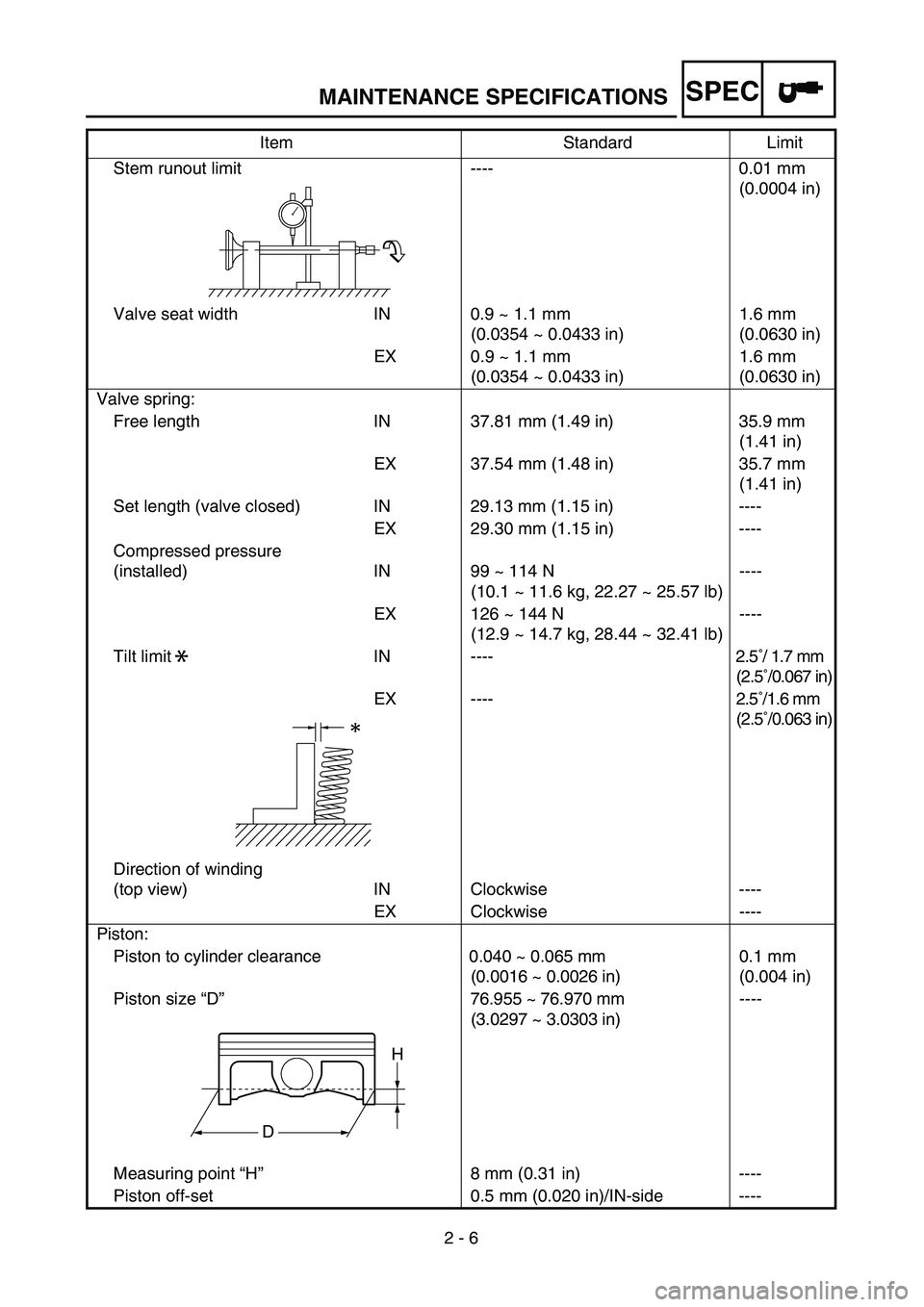
Stem runout limit ---- 0.01 mm
(0.0004 in)
Valve seat width IN 0.9 ~ 1.1 mm
(0.0354 ~ 0.0433 in)1.6 mm
(0.0630 in)
EX 0.9 ~ 1.1 mm
(0.0354 ~ 0.0433 in)1.6 mm
(0.0630 in)
Valve spring:
Free length IN 37.81 mm (1.49 in) 35.9 mm
(1.41 in)
EX 37.54 mm (1.48 in) 35.7 mm
(1.41 in)
Set length (valve closed) IN 29.13 mm (1.15 in) ----
EX 29.30 mm (1.15 in) ----
Compressed pressure
(installed) IN 99 ~ 114 N
(10.1 ~ 11.6 kg, 22.27 ~ 25.57 lb)----
EX 126 ~ 144 N
(12.9 ~ 14.7 kg, 28.44 ~ 32.41 lb)----
Tilt limit IN ---- 2.5˚/ 1.7 mm
(2.5˚/0.067 in)
EX ---- 2.5˚/1.6 mm
(2.5˚/0.063 in)
Direction of winding
(top view) IN Clockwise ----
EX Clockwise ----
Piston:
Piston to cylinder clearance 0.040 ~ 0.065 mm
(0.0016 ~ 0.0026 in)0.1 mm
(0.004 in)
Piston size “D”76.955 ~ 76.970 mm
(3.0297 ~ 3.0303 in)----
Measuring point “H”8 mm (0.31 in) ----
Piston off-set 0.5 mm (0.020 in)/IN-side ----Item Standard Limit
*
H
D
Page 82 of 666
SPEC
2 - 7
MAINTENANCE SPECIFICATIONS
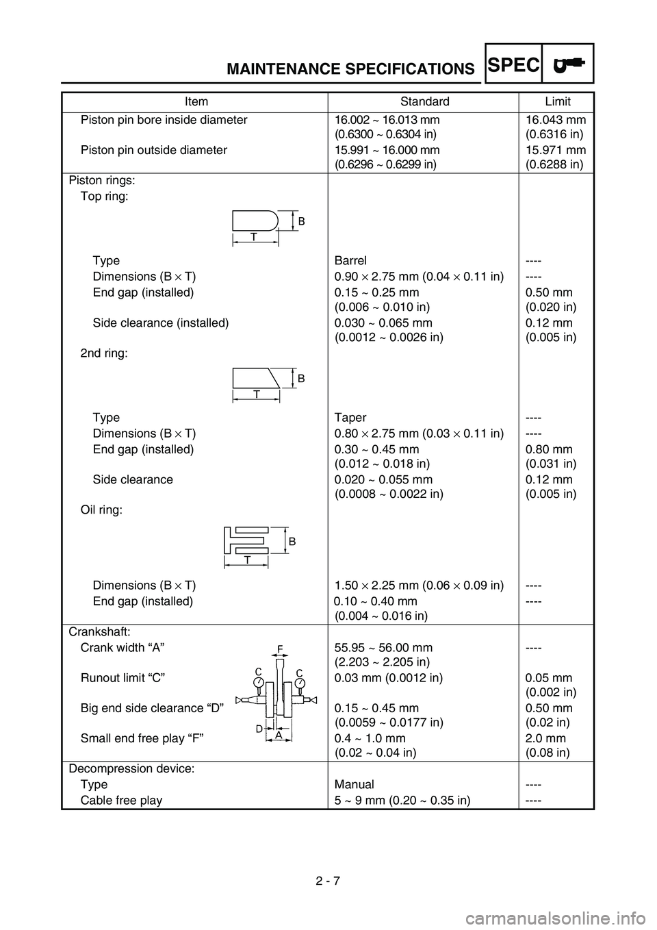
Piston pin bore inside diameter16.002 ~ 16.013 mm
(0.6300 ~ 0.6304 in)16.043 mm
(0.6316 in)
Piston pin outside diameter15.991 ~ 16.000 mm
(0.6296 ~ 0.6299 in)15.971 mm
(0.6288 in)
Piston rings:
Top ring:
Type Barrel ----
Dimensions (B
×
T) 0.90
×
2.75 mm (0.04
×
0.11 in) ----
End gap (installed) 0.15 ~ 0.25 mm
(0.006 ~ 0.010 in)0.50 mm
(0.020 in)
Side clearance (installed) 0.030 ~ 0.065 mm
(0.0012 ~ 0.0026 in)0.12 mm
(0.005 in)
2nd ring:
Type Taper ----
Dimensions (B
×
T) 0.80
×
2.75 mm (0.03
×
0.11 in) ----
End gap (installed) 0.30 ~ 0.45 mm
(0.012 ~ 0.018 in)0.80 mm
(0.031 in)
Side clearance 0.020 ~ 0.055 mm
(0.0008 ~ 0.0022 in)0.12 mm
(0.005 in)
Oil ring:
Dimensions (B
×
T) 1.50
×
2.25 mm (0.06
×
0.09 in) ----
End gap (installed) 0.10 ~ 0.40 mm
(0.004 ~ 0.016 in)----
Crankshaft:
Crank width “A”55.95 ~ 56.00 mm
(2.203 ~ 2.205 in)----
Runout limit “C”0.03 mm (0.0012 in) 0.05 mm
(0.002 in)
Big end side clearance “D”0.15 ~ 0.45 mm
(0.0059 ~ 0.0177 in)0.50 mm
(0.02 in)
Small end free play “F”0.4 ~ 1.0 mm
(0.02 ~ 0.04 in)2.0 mm
(0.08 in)
Decompression device:
Type Manual ----
Cable free play 5 ~ 9 mm (0.20 ~ 0.35 in) ----Item Standard Limit
T
B
B
T
B
T
Page 83 of 666
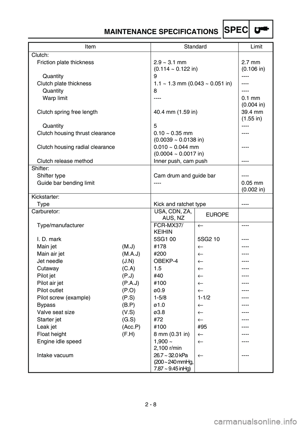
SPEC
2 - 8
MAINTENANCE SPECIFICATIONS
Clutch:
Friction plate thickness 2.9 ~ 3.1 mm
(0.114 ~ 0.122 in)2.7 mm
(0.106 in)
Quantity 9 ----
Clutch plate thickness 1.1 ~ 1.3 mm (0.043 ~ 0.051 in) ----
Quantity 8 ----
Warp limit ---- 0.1 mm
(0.004 in)
Clutch spring free length 40.4 mm (1.59 in) 39.4 mm
(1.55 in)
Quantity 5 ----
Clutch housing thrust clearance 0.10 ~ 0.35 mm
(0.0039 ~ 0.0138 in)----
Clutch housing radial clearance 0.010 ~ 0.044 mm
(0.0004 ~ 0.0017 in)----
Clutch release method Inner push, cam push ----
Shifter:
Shifter type Cam drum and guide bar ----
Guide bar bending limit ---- 0.05 mm
(0.002 in)
Kickstarter:
Type Kick and ratchet type ----
Carburetor: USA, CDN, ZA,
AUS, NZEUROPE
Type/manufacturer FCR-MX37/
KEIHIN
←
----
I. D. mark 5SG1 00 5SG2 10 ----
Main jet (M.J) #178
←
----
Main air jet (M.A.J) #200
←
----
Jet needle (J.N) OBEKP-4
←
----
Cutaway (C.A) 1.5
←
----
Pilot jet (P.J) #40
←
----
Pilot air jet (P.A.J) #100
←
----
Pilot outlet (P.O)ø0.9
←
----
Pilot screw (example) (P.S) 1-5/8 1-1/2 ----
Bypass (B.P)ø1.0
←
----
Valve seat size (V.S)ø3.8
←
----
Starter jet (G.S) #72
←
----
Leak jet (Acc.P) #100 #95 ----
Float height (F.H) 8 mm (0.31 in)
←
----
Engine idle speed 1,900 ~
2,100 r/min
←
----
Intake vacuum26.7 ~ 32.0 kPa
(200 ~ 240 mmHg,
7.87 ~ 9.45 inHg)
←
---- Item Standard Limit
Page 84 of 666
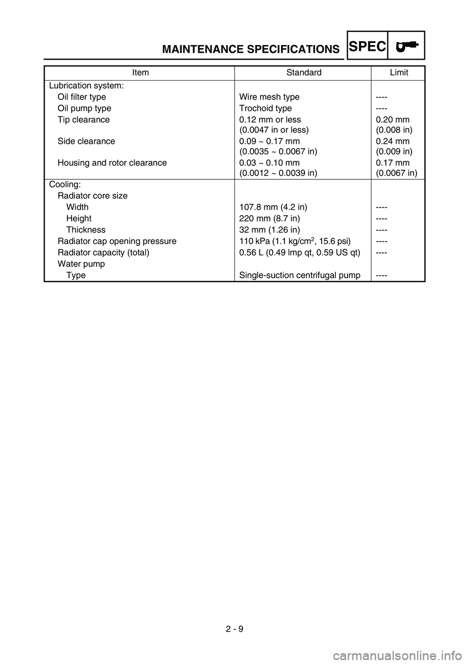
SPEC
2 - 9
MAINTENANCE SPECIFICATIONS
Lubrication system:
Oil filter type Wire mesh type ----
Oil pump type Trochoid type ----
Tip clearance 0.12 mm or less
(0.0047 in or less)0.20 mm
(0.008 in)
Side clearance 0.09 ~ 0.17 mm
(0.0035 ~ 0.0067 in)0.24 mm
(0.009 in)
Housing and rotor clearance 0.03 ~ 0.10 mm
(0.0012 ~ 0.0039 in)0.17 mm
(0.0067 in)
Cooling:
Radiator core size
Width 107.8 mm (4.2 in) ----
Height 220 mm (8.7 in) ----
Thickness 32 mm (1.26 in) ----
Radiator cap opening pressure110 kPa (1.1 kg/cm
2
, 15.6 psi)----
Radiator capacity (total) 0.56 L (0.49 lmp qt, 0.59 US qt) ----
Water pump
Type Single-suction centrifugal pump ----Item Standard Limit