clutch YAMAHA YZ250F 2005 Betriebsanleitungen (in German)
[x] Cancel search | Manufacturer: YAMAHA, Model Year: 2005, Model line: YZ250F, Model: YAMAHA YZ250F 2005Pages: 668, PDF-Größe: 15.74 MB
Page 142 of 668
2 - 18
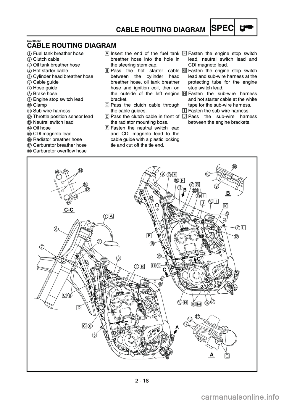
SPECCABLE ROUTING DIAGRAM
EC240000
CABLE ROUTING DIAGRAM
1Fuel tank breather hose
2Clutch cable
3Oil tank breather hose
4Hot starter cable
5Cylinder head breather hose
6Cable guide
7Hose guide
8Brake hose
9Engine stop switch lead
0Clamp
ASub-wire harness
BThrottle position sensor lead
CNeutral switch lead
DOil hose
ECDI magneto lead
FRadiator breather hose
GCarburetor breather hose
HCarburetor overflow hoseÈInsert the end of the fuel tank
breather hose into the hole in
the steering stem cap.
ÉPass the hot starter cable
between the cylinder head
breather hose, oil tank breather
hose and ignition coil, then on
the outside of the left engine
bracket.
ÊPass the clutch cable through
the cable guides.
ËPass the clutch cable in front of
the radiator mounting boss.
ÌFasten the neutral switch lead
and CDI magneto lead to the
cable guide with a plastic locking
tie and cut off the tie end.ÍFasten the engine stop switch
lead, neutral switch lead and
CDI magneto lead.
ÎFasten the engine stop switch
lead and sub-wire harness at the
protecting tube for the engine
stop switch lead.
ÏFasten the sub-wire harness
and hot starter cable at the white
tape for the sub-wire harness.
ÐFasten the sub-wire harness.
ÑPass the sub-wire harness
between the engine brackets.
B
E
C
9
B
C
C
9
0
0
A
0
0
0
0
B 0 Ì
Í
Î
Ï
Ð
Ð
Ñ
Ò
Ó
C
D
0 0 0E F
Ô Õ Ö ×
1
2
3
4
5 6 6 8
7
Ê
Ê ËÈ
É
AGG
H
Ø
D
F
C
Page 150 of 668

2 - 22
SPECCABLE ROUTING DIAGRAM
1Throttle cable
2Fuel tank breather hose
3Clamp
4Clutch cable
5Hot starter cable
6Engine stop switch lead
7Brake hose
8Hose guideÈFasten the engine stop switch lead to the handlebar.
ÉPass the brake hose in front of the number plate.
123
4
5
6
7
8 È
É
40˚±10˚
A
A
3
6
Page 152 of 668
3 - 1
INSP
ADJ
MAINTENANCE INTERVALS
EC300000
REGULAR INSPECTION AND ADJUSTMENTS
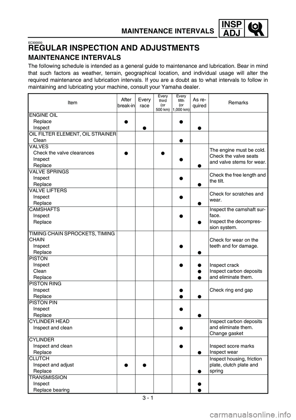
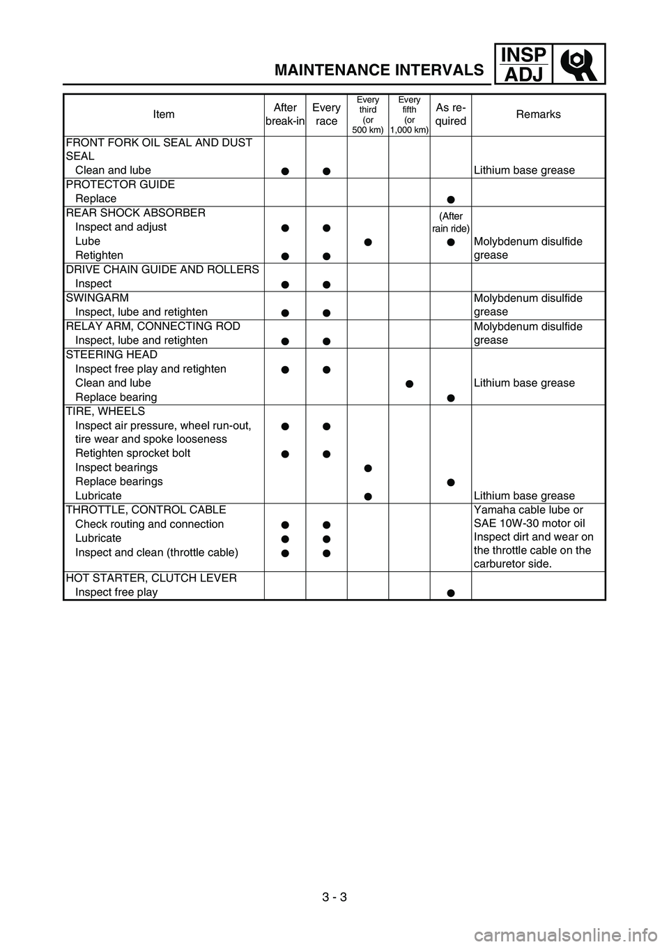
MAINTENANCE INTERVALS
The following schedule is intended as a general guide to maintenance and lubrication. Bear in mind
that such factors as weather, terrain, geographical location, and individual usage will alter the
required maintenance and lubrication intervals. If you are a doubt as to what intervals to follow in
maintaining and lubricating your machine, consult your Yamaha dealer.
ItemAfter
break-inEvery
race
Every
third
(or
500 km)Every
fifth
(or
1,000 km)As re-
quiredRemarks
ENGINE OIL
Replace
Inspect
OIL FILTER ELEMENT, OIL STRAINER
Clean
VALVES
The engine must be cold.
Check the valve seats
and valve stems for wear. Check the valve clearances
Inspect
Replace
VALVE SPRINGS
Check the free length and
the tilt. Inspect
Replace
VALVE LIFTERS
Check for scratches and
wear. Inspect
Replace
CAMSHAFTS Inspect the camshaft sur-
face.
Inspect the decompres-
sion system. Inspect
Replace
TIMING CHAIN SPROCKETS, TIMING
CHAIN
Check for wear on the
teeth and for damage. Inspect
Replace
PISTON
Inspect
Inspect crack
Inspect carbon deposits
and eliminate them. Clean
Replace
PISTON RING
InspectCheck ring end gap
Replace
PISTON PIN
Inspect
Replace
CYLINDER HEAD Inspect carbon deposits
and eliminate them.
Change gasket Inspect and clean
CYLINDER
Inspect and clean
Inspect score marks
Inspect wear
Replace
CLUTCH
Inspect housing, friction
plate, clutch plate and
spring Inspect and adjust
Replace
TRANSMISSION
Inspect
Replace bearing
Page 154 of 668
3 - 3
INSP
ADJ
MAINTENANCE INTERVALS
FRONT FORK OIL SEAL AND DUST
SEAL
Clean and lube Lithium base grease
PROTECTOR GUIDE
Replace
REAR SHOCK ABSORBER
(After
rain ride)
Inspect and adjust
Lube
Molybdenum disulfide
grease
Retighten
DRIVE CHAIN GUIDE AND ROLLERS
Inspect
SWINGARM
Molybdenum disulfide
grease
Inspect, lube and retighten
RELAY ARM, CONNECTING ROD
Molybdenum disulfide
grease
Inspect, lube and retighten
STEERING HEAD
Inspect free play and retighten
Clean and lube Lithium base grease
Replace bearing
TIRE, WHEELS
Inspect air pressure, wheel run-out,
tire wear and spoke looseness
Retighten sprocket bolt
Inspect bearings
Replace bearings
Lubricate Lithium base grease
THROTTLE, CONTROL CABLE Yamaha cable lube or
SAE 10W-30 motor oil
Inspect dirt and wear on
the throttle cable on the
carburetor side. Check routing and connection
Lubricate
Inspect and clean (throttle cable)
HOT STARTER, CLUTCH LEVER
Inspect free playItemAfter
break-inEvery
race
Every
third
(or
500 km)Every
fifth
(or
1,000 km)As re-
quiredRemarks
Page 164 of 668
3 - 4
INSP
ADJ
PRE-OPERATION INSPECTION AND MAINTENANCE
EC320000
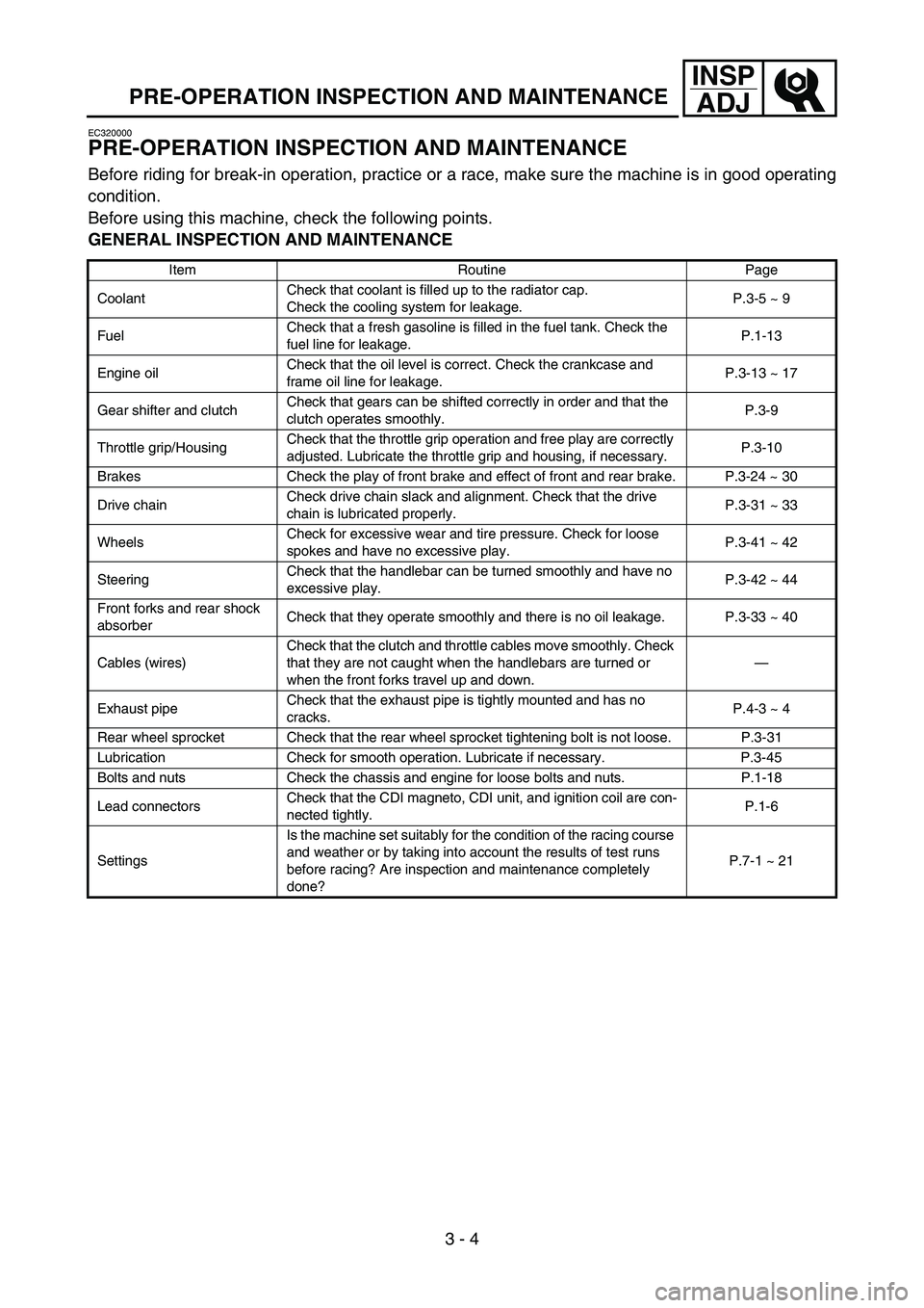
PRE-OPERATION INSPECTION AND MAINTENANCE
Before riding for break-in operation, practice or a race, make sure the machine is in good operating
condition.
Before using this machine, check the following points.
GENERAL INSPECTION AND MAINTENANCE
Item Routine Page
CoolantCheck that coolant is filled up to the radiator cap.
Check the cooling system for leakage.P.3-5 ~ 9
FuelCheck that a fresh gasoline is filled in the fuel tank. Check the
fuel line for leakage.P.1-13
Engine oilCheck that the oil level is correct. Check the crankcase and
frame oil line for leakage.P.3-13 ~ 17
Gear shifter and clutchCheck that gears can be shifted correctly in order and that the
clutch operates smoothly.P.3-9
Throttle grip/HousingCheck that the throttle grip operation and free play are correctly
adjusted. Lubricate the throttle grip and housing, if necessary.P.3-10
Brakes Check the play of front brake and effect of front and rear brake. P.3-24 ~ 30
Drive chainCheck drive chain slack and alignment. Check that the drive
chain is lubricated properly.P.3-31 ~ 33
WheelsCheck for excessive wear and tire pressure. Check for loose
spokes and have no excessive play.P.3-41 ~ 42
SteeringCheck that the handlebar can be turned smoothly and have no
excessive play.P.3-42 ~ 44
Front forks and rear shock
absorberCheck that they operate smoothly and there is no oil leakage. P.3-33 ~ 40
Cables (wires)Check that the clutch and throttle cables move smoothly. Check
that they are not caught when the handlebars are turned or
when the front forks travel up and down.—
Exhaust pipeCheck that the exhaust pipe is tightly mounted and has no
cracks.P.4-3 ~ 4
Rear wheel sprocket Check that the rear wheel sprocket tightening bolt is not loose. P.3-31
Lubrication Check for smooth operation. Lubricate if necessary. P.3-45
Bolts and nuts Check the chassis and engine for loose bolts and nuts. P.1-18
Lead connectorsCheck that the CDI magneto, CDI unit, and ignition coil are con-
nected tightly.P.1-6
SettingsIs the machine set suitably for the condition of the racing course
and weather or by taking into account the results of test runs
before racing? Are inspection and maintenance completely
done?P.7-1 ~ 21
Page 176 of 668
3 - 9
INSP
ADJ
CLUTCH ADJUSTMENT
NOTE:
Do not apply pressure more than specified
pressure.
Radiator should be filled fully.
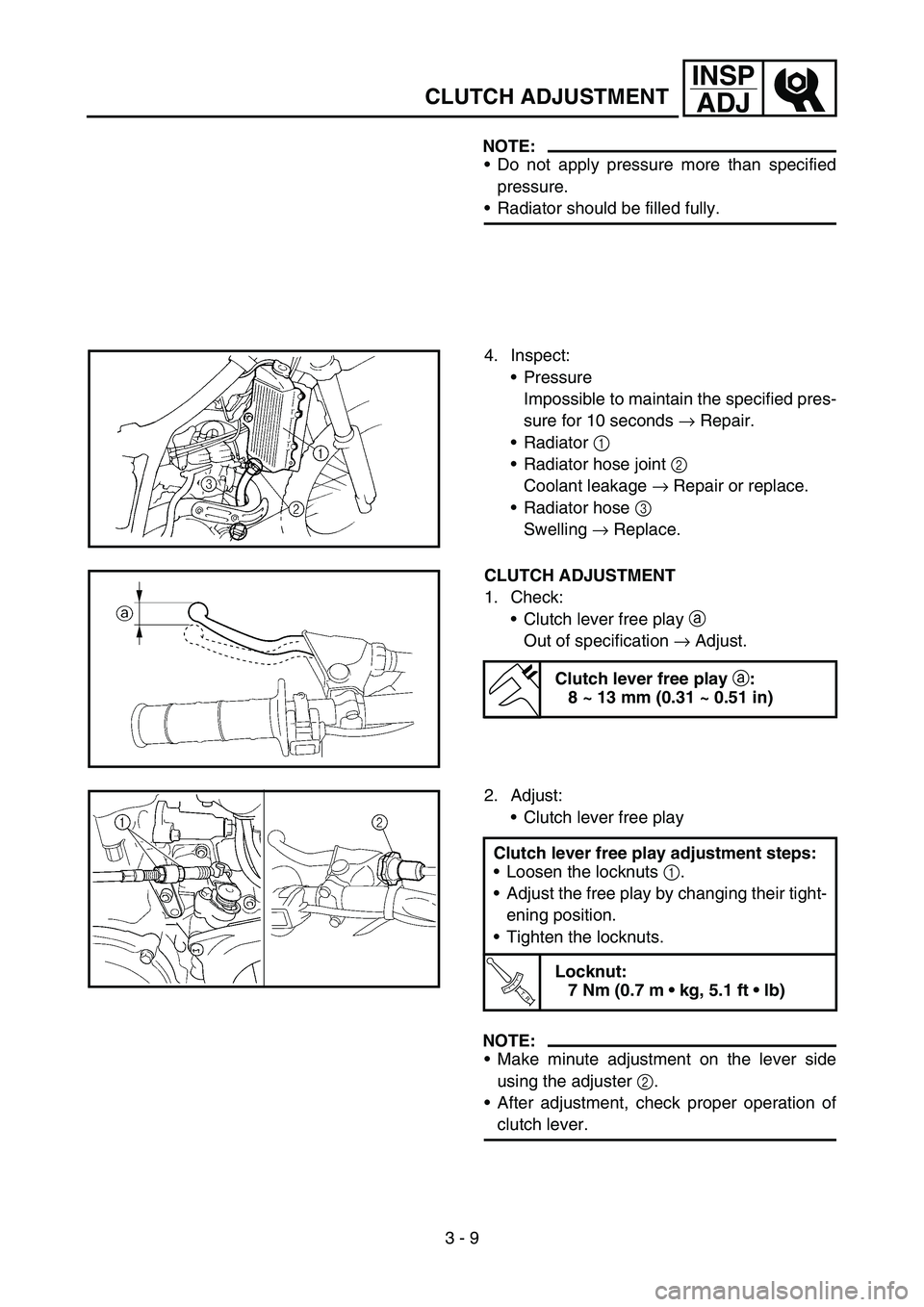
4. Inspect:
Pressure
Impossible to maintain the specified pres-
sure for 10 seconds → Repair.
Radiator 1
Radiator hose joint 2
Coolant leakage → Repair or replace.
Radiator hose 3
Swelling → Replace.
CLUTCH ADJUSTMENT
1. Check:
Clutch lever free play a
Out of specification → Adjust.
Clutch lever free play
a:
8 ~ 13 mm (0.31 ~ 0.51 in)
2. Adjust:
Clutch lever free play
NOTE:
Make minute adjustment on the lever side
using the adjuster 2.
After adjustment, check proper operation of
clutch lever. Clutch lever free play adjustment steps:
Loosen the locknuts 1.
Adjust the free play by changing their tight-
ening position.
Tighten the locknuts.
T R..
Locknut:
7 Nm (0.7 m kg, 5.1 ft lb)
Page 186 of 668
3 - 14
INSP
ADJ
ENGINE OIL LEVEL INSPECTION
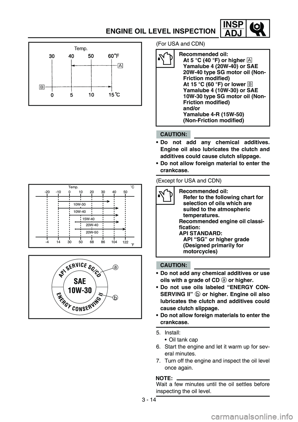
(For USA and CDN)
CAUTION:
Do not add any chemical additives.
Engine oil also lubricates the clutch and
additives could cause clutch slippage.
Do not allow foreign material to enter the
crankcase.
(Except for USA and CDN)
CAUTION:
Do not add any chemical additives or use
oils with a grade of CD
a or higher.
Do not use oils labeled “ENERGY CON-
SERVING II”
b or higher. Engine oil also
lubricates the clutch and additives could
cause clutch slippage.
Do not allow foreign materials to enter the
crankcase.
5. Install:
Oil tank cap
6. Start the engine and let it warm up for sev-
eral minutes.
7. Turn off the engine and inspect the oil level
once again.
NOTE:
Wait a few minutes until the oil settles before
inspecting the oil level.
Recommended oil:
At 5 °C (40 °F) or higher
È
Yamalube 4 (20W-40) or SAE
20W-40 type SG motor oil (Non-
Friction modified)
At 15 °C (60 °F) or lower
É
Yamalube 4 (10W-30) or SAE
10W-30 type SG motor oil (Non-
Friction modified)
and/or
Yamalube 4-R (15W-50)
(Non-Friction modified)
Recommended oil:
Refer to the following chart for
selection of oils which are
suited to the atmospheric
temperatures.
Recommended engine oil classi-
fication:
API STANDARD:
API “SG” or higher grade
(Designed primarily for
motorcycles)-20
-4-10
140
3010
5020
6830
8640 50
104
122 ˚CTemp.
˚F
10W-30
10W-40
20W-40
20W-50
15W-40
a
b
Page 250 of 668
3 - 45
INSP
ADJ
LUBRICATION
LUBRICATION
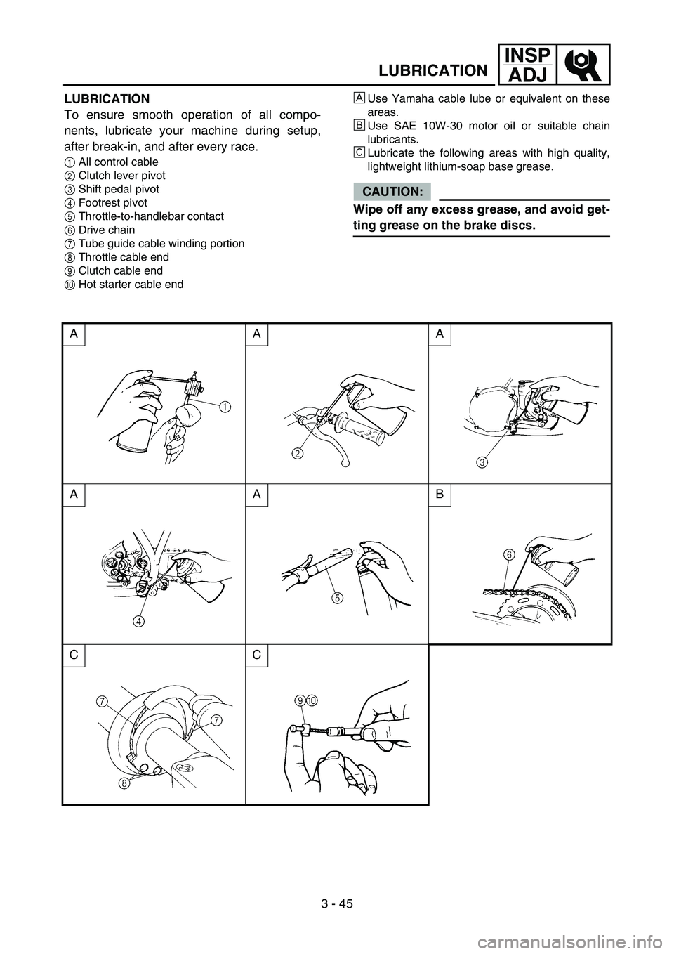
To ensure smooth operation of all compo-
nents, lubricate your machine during setup,
after break-in, and after every race.
1All control cable
2Clutch lever pivot
3Shift pedal pivot
4Footrest pivot
5Throttle-to-handlebar contact
6Drive chain
7Tube guide cable winding portion
8Throttle cable end
9Clutch cable end
0Hot starter cable end
ÈUse Yamaha cable lube or equivalent on these
areas.
ÉUse SAE 10W-30 motor oil or suitable chain
lubricants.
ÊLubricate the following areas with high quality,
lightweight lithium-soap base grease.
CAUTION:
Wipe off any excess grease, and avoid get-
ting grease on the brake discs.
AAA
AAB
CC
Page 352 of 668
4 - 49
ENGCLUTCH
EC4A0000
CLUTCH
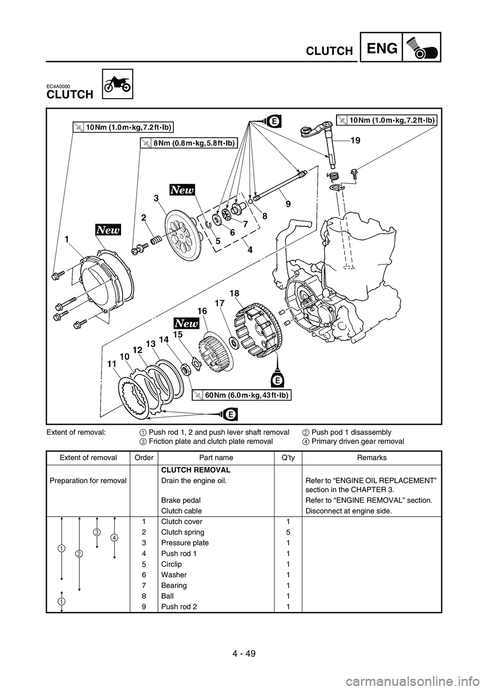
Extent of removal:
1 Push rod 1, 2 and push lever shaft removal
2 Push pod 1 disassembly
3 Friction plate and clutch plate removal
4 Primary driven gear removal
Extent of removal Order Part name Q’ty Remarks
CLUTCH REMOVAL
Preparation for removal Drain the engine oil. Refer to “ENGINE OIL REPLACEMENT”
section in the CHAPTER 3.
Brake pedal Refer to “ENGINE REMOVAL” section.
Clutch cable Disconnect at engine side.
1 Clutch cover 1
2 Clutch spring 5
3 Pressure plate 1
4 Push rod 1 1
5 Circlip 1
6 Washer 1
7 Bearing 1
8Ball 1
9 Push rod 2 1
1
4
1
3
2
Page 354 of 668
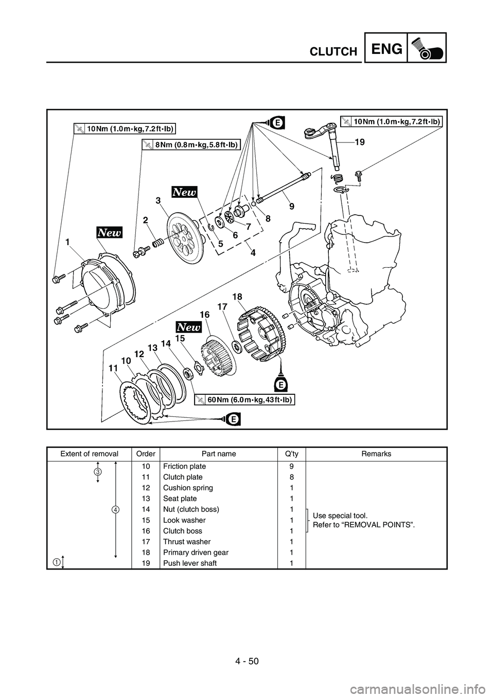
4 - 50
ENGCLUTCH
Extent of removal Order Part name Q’ty Remarks
10 Friction plate 9
11 Clutch plate 8
12 Cushion spring 1
13 Seat plate 1
14 Nut (clutch boss) 1
Use special tool.
Refer to “REMOVAL POINTS”. 15 Look washer 1
16 Clutch boss 1
17 Thrust washer 1
18 Primary driven gear 1
19 Push lever shaft 1
4
1
3