YAMAHA YZ250F 2005 Betriebsanleitungen (in German)
Manufacturer: YAMAHA, Model Year: 2005, Model line: YZ250F, Model: YAMAHA YZ250F 2005Pages: 668, PDF-Größe: 15.74 MB
Page 291 of 668
ENG
4 - 18
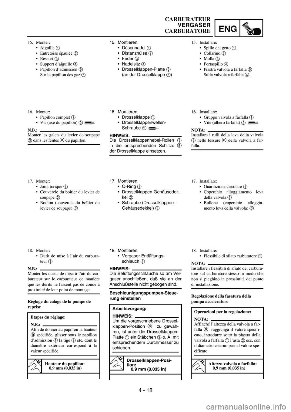
15. Montieren:
Düsennadel
1
Distanzhülse
2
Feder
3
Nadelsitz
4
Drosselklappen-Platte
5
(an der Drosselklappe
6)
16. Montieren:
Drosselklappe
1
Drosselklappenwellen-
Schraube
2
HINWEIS:
Die Drosselklappenhebel-Rollen
3
in die entsprechenden Schlitze
a
der Drosselklappe einsetzen.
17. Montieren:
O-Ring
1
Drosselklappen-Gehäusedek-
kel
2
Schraube (Drosselklappen-
Gehäusedekkel)
3
18. Montieren:
Vergaser-Entlüftungs-
schlauch
1
HINWEIS:
Die Belüftungsschläuche so am Ver-
gaser anschließen, daß sie an der
Anschlußstelle nicht gebogen sind.
Beschleunigungspumpen-Steue-
rung einstellen
Arbeitsvorgang:
HINWEIS:
Um die vorgeschriebene Drossel-
klappen-Position
a zu gewäh-
ren, ist unter die Drosselklappen-
Platte
1 ein Stäbchen
2 o. Ä. mit
entsprechendem Durchmesser zu
schieben.
Drosselklappen-Posi-
tion:
0,9 mm (0,035 in)
15. Monter:
Aiguille 1
Entretoise épaulée 2
Ressort 3
Support d’aiguille 4
Papillon d’admission 5
Sur le papillon des gaz 6
16. Monter:
Papillon complet 1
Vis (axe du papillon) 2
N.B.:
Monter les galets du levier de soupape
3 dans les fentes a du papillon.
17. Monter:
Joint torique 1
Couvercle du boîtier du levier de
soupape 2
Boulon (couvercle du boîtier du
levier de soupape) 3
18. Monter:
Durit de mise à l’air du carbura-
teur 1
N.B.:
Monter les durits de mise à l’air du car-
burateur sur le carburateur de manière
que les durits ne fassent pas de coude à
proximité de leur point de montage.
Réglage du calage de la pompe de
reprise
Etapes du réglage:
N.B.:
Afin de donner au papillon la hauteur
a spécifiée, glisser sous le papillon
d’admission 1 la tige 2 etc. dont le
diamètre extérieur correspond à la
valeur spécifiée.
Hauteur du papillon:
0,9 mm (0,035 in)
15. Installare:
Spillo del getto 1
Collarino 2
Molla 3
Portaspillo 4
Piastra valvola a farfalla 5
Sulla valvola a farfalla 6.
16. Installare:
Gruppo valvola a farfalla 1
Vite (albero farfalla) 2
NOTA:
Installare i rulli della leva della valvola
3 nelle fessure a della valvola a far-
falla.
17. Installare:
Guarnizione circolare 1
Coperchio alloggiamento leva
della valvola 2
Bullone (coperchio alloggia-
mento leva della valvola) 3
18. Installare:
Flessibile di sfiato carburatore 1
NOTA:
Installare i flessibili di sfiato del carbura-
tore sul carburatore stesso in modo che
non si pieghino in prossimità del punto
di installazione.
Regolazione della fasatura della
pompa acceleratore
Operazioni per la regolazione:
NOTA:
Affinché l’altezza della valvola a far-
falla a raggiunga il valore specifi-
cato, introdurre sotto la piastra della
valvola a farfalla 1 l’asta 2 ecc. con
il diametro esterno pari al valore spe-
cificato.
Altezza valvola a farfalla:
0,9 mm (0,035 in)
CARBURATEUR
VERGASER
CARBURATORE
Page 292 of 668
4 - 19
ENGCARBURETOR
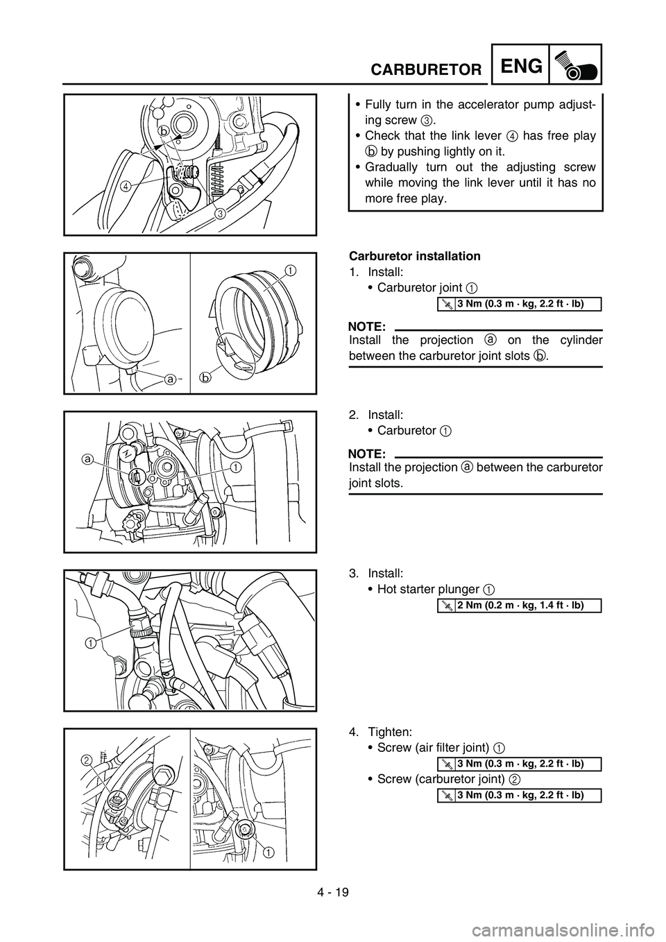
Fully turn in the accelerator pump adjust-
ing screw 3.
Check that the link lever 4 has free play
b by pushing lightly on it.
Gradually turn out the adjusting screw
while moving the link lever until it has no
more free play.
Carburetor installation
1. Install:
Carburetor joint 1
NOTE:
Install the projection a on the cylinder
between the carburetor joint slots b.
T R..3 Nm (0.3 m · kg, 2.2 ft · lb)
2. Install:
Carburetor 1
NOTE:
Install the projection a between the carburetor
joint slots.
3. Install:
Hot starter plunger 1
1
T R..2 Nm (0.2 m · kg, 1.4 ft · lb)
4. Tighten:
Screw (air filter joint) 1
Screw (carburetor joint) 2
T R..3 Nm (0.3 m · kg, 2.2 ft · lb)
T R..3 Nm (0.3 m · kg, 2.2 ft · lb)
Page 293 of 668
ENG
4 - 19
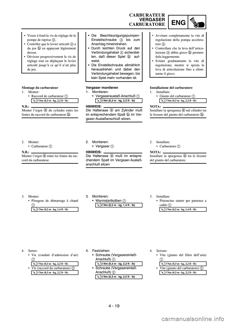
Die Beschleunigungspumpen-
Einstellschraube
3 bis zum
Anschlag hineindrehen.
Durch leichten Druck auf den
Verbindungshebel
4 sicherstel-
len, daß dieser Spiel
b auf-
weist.
Die Einstellschraube allmählich
herausdrehen und dabei den
Verbindungshebel bewegen, bis
kein Spiel mehr vorhanden ist.
Vergaser montieren
1. Montieren:
Vergaserauslaß-Anschluß
1
HINWEIS:
Die Haltenase
a am Zylinder muß
im entsprechendem Spalt
b im Ver-
gaser-Auslaßanschluß sitzen.
T R..3 Nm (0,3 m · kg, 2,2 ft · lb)
2. Montieren:
Vergaser
1
HINWEIS:
Die Haltenase
a muß im entspre-
chendem Spalt im Vergaser-Auslaß-
anschluß sitzen
3. Montieren:
Warmstartkolben
1
T R..2 Nm (0,2 m · kg, 1,4 ft · lb)
4. Festziehen:
Schraube (Vergasereinlaß-
Anschluß)
1
Schraube (Vergasereinlaß-
Anschluß)
2
T R..3 Nm (0,3 m · kg, 2,2 ft · lb)
T R..3 Nm (0,3 m · kg, 2,2 ft · lb)
Visser à fond la vis de réglage de la
pompe de reprise 3.
Contrôler que le levier articulé 4 a
du jeu b en appuyant légèrement
dessus.
Dévisser progressivement la vis de
réglage tout en déplaçant le levier
articulé jusqu’à ce qu’il n’ait plus
de jeu.
Montage du carburateur
1. Monter:
Raccord de carburateur 1
N.B.:
Monter l’ergot a du cylindre entre les
fentes du raccord de carburateur b.
T R..3 Nm (0,3 m · kg, 2,2 ft · lb)
2. Monter:
Carburateur 1
N.B.:
Monter l’ergot a entre les fentes du rac-
cord du carburateur.
3. Monter:
Plongeur de démarrage à chaud
1
T R..2 Nm (0,2 m · kg, 1,4 ft · lb)
4. Serrer:
Vis (conduit d’admission d’air)
1
Vis (raccord du carburateur) 2
T R..3 Nm (0,3 m · kg, 2,2 ft · lb)
T R..3 Nm (0,3 m · kg, 2,2 ft · lb)
Avvitare completamente la vite di
regolazione della pompa accelera-
tore 3.
Controllare che la leva dell’artico-
lazione 4 abbia gioco b premen-
dola leggermente.
Svitare gradatamente la vite di
regolazione, mentre si sposta la
leva di articolazione fino a elimi-
narne il gioco.
Installazione del carburatore
1. Installare:
Giunto del carburatore 1
NOTA:
Installare la sporgenza a nel cilindro tra
le fessure del giunto del carburatore b.
T R..3 Nm (0,3 m · kg, 2,2 ft · lb)
2. Installare:
Carburatore 1
NOTA:
Installare la sporgenza a tra le fessure
del giunto del carburatore.
3. Installare:
Pistoncino starter per partenze a
caldo 1
T R..2 Nm (0,2 m · kg, 1,4 ft · lb)
4. Serrare:
Vite (giunto del filtro dell’aria)
1
Vite (giunto del carburatore) 2
T R..3 Nm (0,3 m · kg, 2,2 ft · lb)
T R..3 Nm (0,3 m · kg, 2,2 ft · lb)
CARBURATEUR
VERGASER
CARBURATORE
Page 294 of 668

4 - 20
ENG
5. Install:
Throttle cable (pull) 1
Throttle cable (return) 2
6. Adjust:
Throttle grip free play
Refer to “THROTTLE CABLE ADJUST-
MENT” section in the CHAPTER 3.2
1
T R..4 Nm (0.4 m · kg, 2.9 ft · lb)
T R..11 Nm (1.1 m · kg, 8.0 ft · lb)
7. Install:
Throttle cable cover 1
Screw (throttle cable cover) 2
2 1
T R..4 Nm (0.4 m · kg, 2.9 ft · lb)
8. Install:
Throttle position sensor lead coupler 1
Clamp 2
Refer to “CABLE ROUTING DIAGRAM”
section in the CHAPTER 2.
CARBURETOR
Page 295 of 668

ENG
4 - 20
5. Montieren:
Gasgeberzug
1
Gasnehmerzug
2
6. Einstellen:
Gaszugspiel am Gasdrehgriff
Siehe unter “GASZUG EIN-
STELLEN” in KAPITEL 3.
T R..4 Nm (0,4 m · kg, 2,9 ft · lb)
T R..11 Nm (1,1 m · kg, 8,0 ft · lb)
7. Montieren:
Gaszug-Abdeckung
1
Schraube (Gaszug-Abdek-
kung)
2
T R..4 Nm (0,4 m · kg, 2,9 ft · lb)
8. Montieren:
Drosselklappensensor-Steck-
verbinder
1
Klemme
2
Siehe unter “KABELFÜH-
RUNGSDIAGRAMME” in
KAPITEL 2. 5. Monter:
Câble des gaz (tiré) 1
Câble des gaz (retour) 2
6. Régler:
Jeu de la poignée des gaz
Se reporter à la section
“REGLAGE DU CABLE DES
GAZ” au CHAPITRE 3.
T R..4 Nm (0,4 m · kg, 2,9 ft · lb)
T R..11 Nm (1,1 m · kg, 8,0 ft · lb)
7. Monter:
Couvercle du logement du câble
des gaz 1
Vis (couvercle du logement de
câble des gaz) 2
T R..4 Nm (0,4 m · kg, 2,9 ft · lb)
8. Monter:
Fiche rapide du fil du capteur de
position de papillon des gaz 1
Collier à pince 2
Se reporter à la section “DIA-
GRAMME D’ACHEMINE-
MENT DES CABLES” au
CHAPITRE 2.5. Installare:
Cavo acceleratore (tirare) 1
Cavo acceleratore (posizione ini-
ziale) 2
6. Regolare:
Gioco manopola acceleratore
Fare riferimento al paragrafo
“REGOLAZIONE CAVO
ACCELERATORE” nel CAPI-
TOLO 3.
T R..4 Nm (0,4 m · kg, 2,9 ft · lb)
T R..11 Nm (1,1 m · kg, 8,0 ft · lb)
7. Installare:
Rivestimento cavo acceleratore
1
Vite (rivestimento cavo accelera-
tore) 2
T R..4 Nm (0,4 m · kg, 2,9 ft · lb)
8. Installare:
Accoppiatore cavo sensore posi-
zione farfalla 1
Morsetto 2
Fare riferimento al paragrafo
“SCHEMA PERCORSO DEI
CAVI” nel CAPITOLO 2.
CARBURATEUR
VERGASER
CARBURATORE
Page 296 of 668
4 - 21
ENGCAMSHAFTS
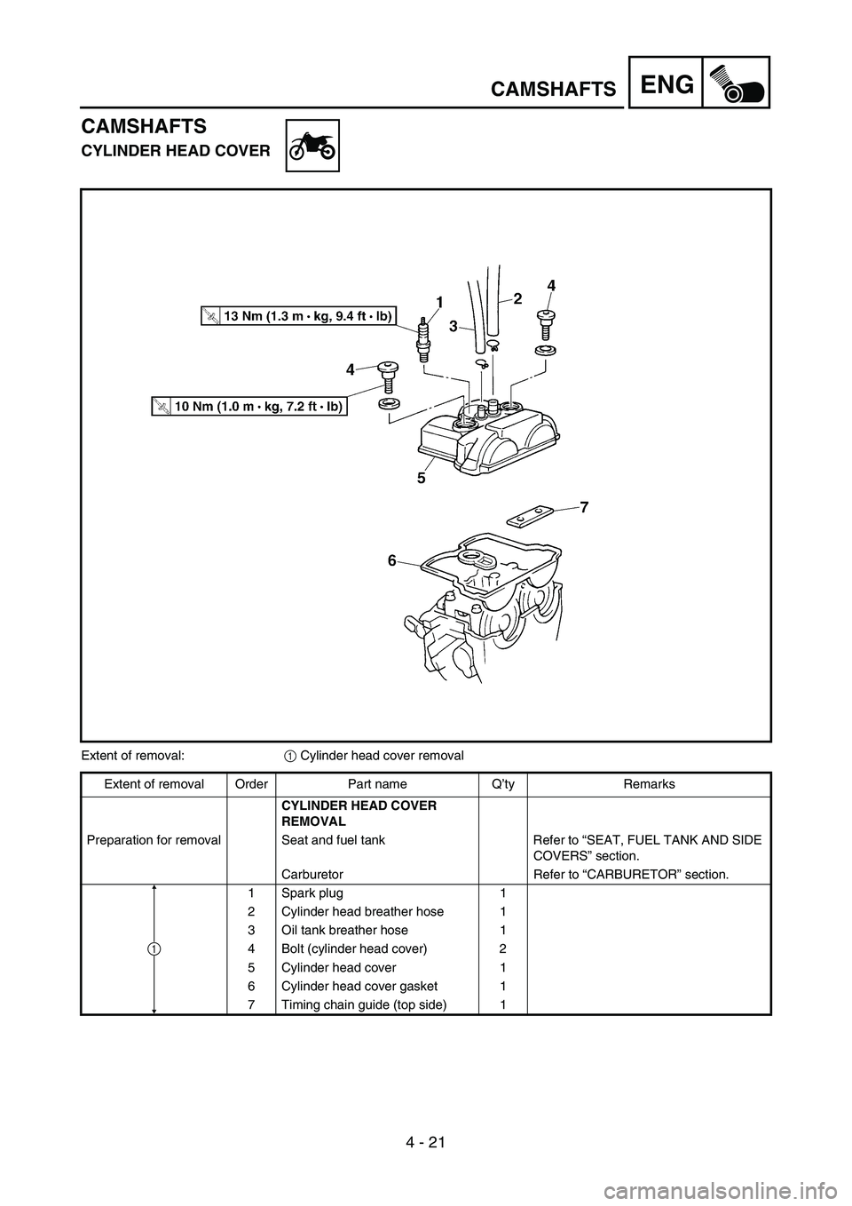
CAMSHAFTS
CYLINDER HEAD COVER
Extent of removal:
1 Cylinder head cover removal
Extent of removal Order Part name Q’ty Remarks
CYLINDER HEAD COVER
REMOVAL
Preparation for removal Seat and fuel tank Refer to “SEAT, FUEL TANK AND SIDE
COVERS” section.
Carburetor Refer to “CARBURETOR” section.
1 Spark plug 1
2 Cylinder head breather hose 1
3 Oil tank breather hose 1
4 Bolt (cylinder head cover) 2
5 Cylinder head cover 1
6 Cylinder head cover gasket 1
7 Timing chain guide (top side) 1
1
Page 297 of 668
ENG
4 - 21
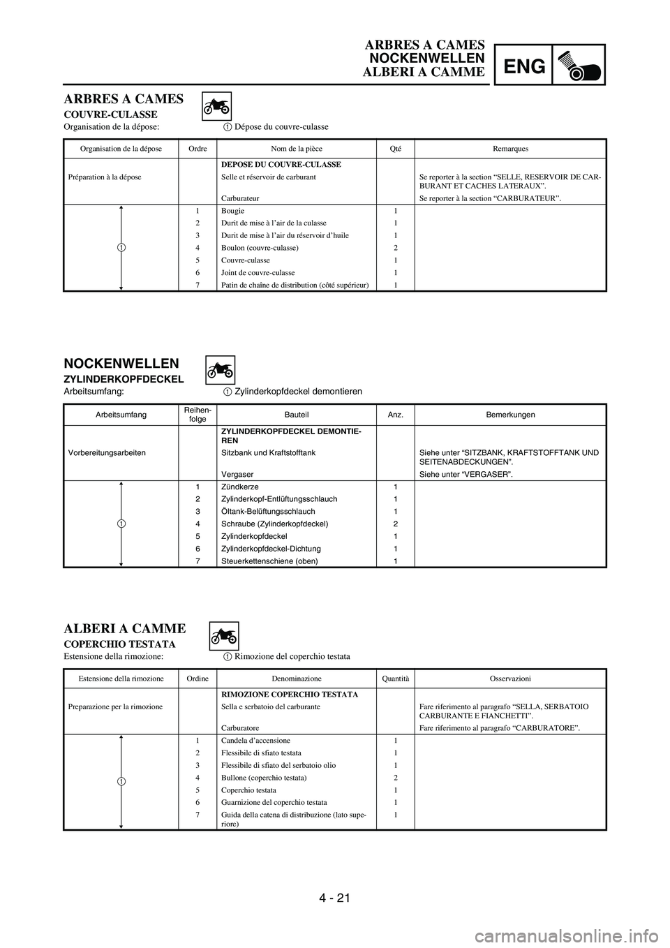
NOCKENWELLEN
ZYLINDERKOPFDECKEL
Arbeitsumfang:
1 Zylinderkopfdeckel demontieren
ArbeitsumfangReihen-
folgeBauteil Anz. Bemerkungen
ZYLINDERKOPFDECKEL DEMONTIE-
REN
Vorbereitungsarbeiten Sitzbank und Kraftstofftank Siehe unter “SITZBANK, KRAFTSTOFFTANK UND
SEITENABDECKUNGEN”.
Vergaser Siehe unter “VERGASER”.
1Zündkerze 1
2 Zylinderkopf-Entlüftungsschlauch 1
3Öltank-Belüftungsschlauch 1
4 Schraube (Zylinderkopfdeckel) 2
5 Zylinderkopfdeckel 1
6 Zylinderkopfdeckel-Dichtung 1
7 Steuerkettenschiene (oben) 1
1
ARBRES A CAMES
COUVRE-CULASSE
Organisation de la dépose:1 Dépose du couvre-culasse
Organisation de la dépose Ordre Nom de la pièce QtéRemarques
DEPOSE DU COUVRE-CULASSE
Préparation à la dépose Selle et réservoir de carburant Se reporter à la section “SELLE, RESERVOIR DE CAR-
BURANT ET CACHES LATERAUX”.
Carburateur Se reporter à la section “CARBURATEUR”.
1 Bougie 1
2 Durit de mise à l’air de la culasse 1
3 Durit de mise à l’air du réservoir d’huile 1
4 Boulon (couvre-culasse) 2
5 Couvre-culasse 1
6 Joint de couvre-culasse 1
7 Patin de chaîne de distribution (côté supérieur) 1
1
ALBERI A CAMME
COPERCHIO TESTATA
Estensione della rimozione:1 Rimozione del coperchio testata
Estensione della rimozione Ordine Denominazione QuantitàOsservazioni
RIMOZIONE COPERCHIO TESTATA
Preparazione per la rimozione Sella e serbatoio del carburante Fare riferimento al paragrafo “SELLA, SERBATOIO
CARBURANTE E FIANCHETTI”.
Carburatore Fare riferimento al paragrafo “CARBURATORE”.
1 Candela d’accensione 1
2 Flessibile di sfiato testata 1
3 Flessibile di sfiato del serbatoio olio 1
4 Bullone (coperchio testata) 2
5 Coperchio testata 1
6 Guarnizione del coperchio testata 1
7 Guida della catena di distribuzione (lato supe-
riore)1
1
ARBRES A CAMES
NOCKENWELLEN
ALBERI A CAMME
Page 298 of 668
4 - 22
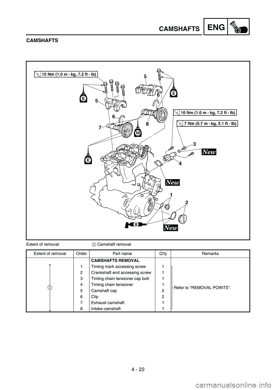
ENGCAMSHAFTS
CAMSHAFTS
Extent of removal:
1 Camshaft removal
Extent of removal Order Part name Q’ty Remarks
CAMSHAFTS REMOVAL
1 Timing mark accessing screw 1
Refer to “REMOVAL POINTS”. 2 Crankshaft end accessing screw 1
3 Timing chain tensioner cap bolt 1
4 Timing chain tensioner 1
5 Camshaft cap 2
6Clip 2
7 Exhaust camshaft 1
8 Intake camshaft 1
1
Page 299 of 668
ENG
4 - 22
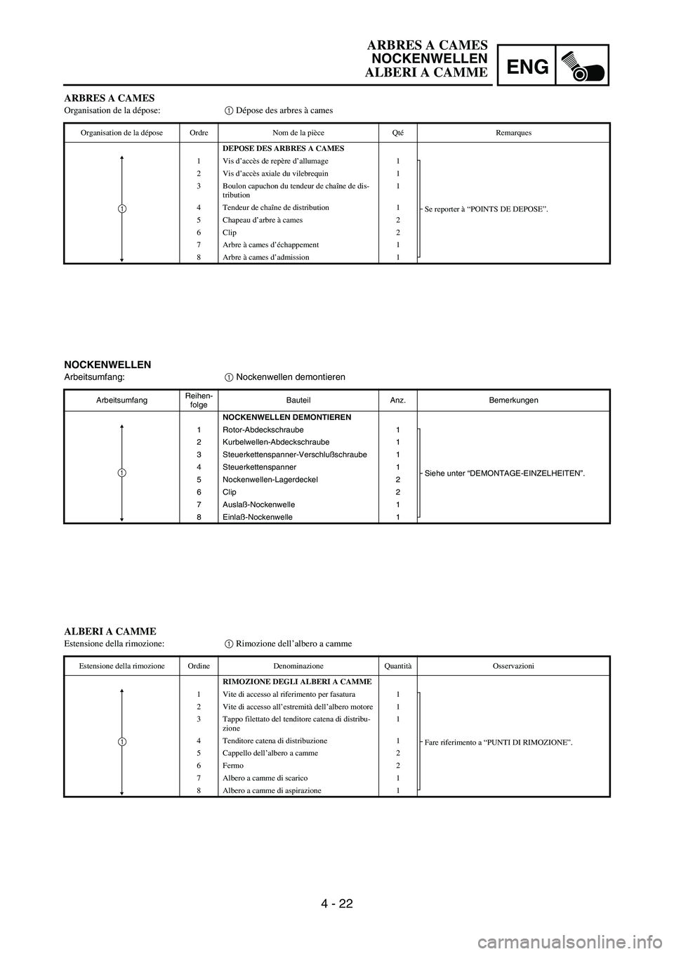
NOCKENWELLEN
Arbeitsumfang:
1 Nockenwellen demontieren
ArbeitsumfangReihen-
folgeBauteil Anz. Bemerkungen
NOCKENWELLEN DEMONTIEREN
1 Rotor-Abdeckschraube 1
Siehe unter “DEMONTAGE-EINZELHEITEN”. 2 Kurbelwellen-Abdeckschraube 1
3 Steuerkettenspanner-Verschlußschraube 1
4 Steuerkettenspanner 1
5 Nockenwellen-Lagerdeckel 2
6 Clip 2
7Auslaß-Nockenwelle 1
8 Einlaß-Nockenwelle 1
1
ARBRES A CAMES
Organisation de la dépose:1 Dépose des arbres à cames
Organisation de la dépose Ordre Nom de la pièce QtéRemarques
DEPOSE DES ARBRES A CAMES
1Vis d’accès de repère d’allumage 1
Se reporter à “POINTS DE DEPOSE”. 2Vis d’accès axiale du vilebrequin 1
3 Boulon capuchon du tendeur de chaîne de dis-
tribution1
4 Tendeur de chaîne de distribution 1
5 Chapeau d’arbre à cames 2
6Clip 2
7 Arbre à cames d’échappement 1
8 Arbre à cames d’admission 1
1
ALBERI A CAMME
Estensione della rimozione:1 Rimozione dell’albero a camme
Estensione della rimozione Ordine Denominazione QuantitàOsservazioni
RIMOZIONE DEGLI ALBERI A CAMME
1 Vite di accesso al riferimento per fasatura 1
Fare riferimento a “PUNTI DI RIMOZIONE”. 2 Vite di accesso all’estremità dell’albero motore 1
3 Tappo filettato del tenditore catena di distribu-
zione1
4 Tenditore catena di distribuzione 1
5 Cappello dell’albero a camme 2
6 Fermo 2
7 Albero a camme di scarico 1
8 Albero a camme di aspirazione 1
1
ARBRES A CAMES
NOCKENWELLEN
ALBERI A CAMME
Page 300 of 668
4 - 23
ENGCAMSHAFTS
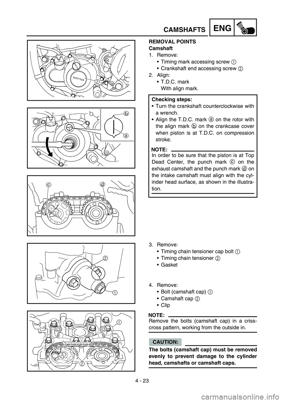
REMOVAL POINTS
Camshaft
1. Remove:
Timing mark accessing screw 1
Crankshaft end accessing screw 2
2. Align:
T.D.C. mark
With align mark.
Checking steps:
Turn the crankshaft counterclockwise with
a wrench.
Align the T.D.C. mark a on the rotor with
the align mark b on the crankcase cover
when piston is at T.D.C. on compression
stroke.
NOTE:
In order to be sure that the piston is at Top
Dead Center, the punch mark c on the
exhaust camshaft and the punch mark d on
the intake camshaft must align with the cyl-
inder head surface, as shown in the illustra-
tion.
3. Remove:
Timing chain tensioner cap bolt 1
Timing chain tensioner 2
Gasket
4. Remove:
Bolt (camshaft cap) 1
Camshaft cap 2
Clip
NOTE:
Remove the bolts (camshaft cap) in a criss-
cross pattern, working from the outside in.
CAUTION:
The bolts (camshaft cap) must be removed
evenly to prevent damage to the cylinder
head, camshafts or camshaft caps.
1
2