fuel YAMAHA YZ250F 2006 Betriebsanleitungen (in German)
[x] Cancel search | Manufacturer: YAMAHA, Model Year: 2006, Model line: YZ250F, Model: YAMAHA YZ250F 2006Pages: 674, PDF-Größe: 21.07 MB
Page 194 of 674
3 - 17
INSP
ADJ
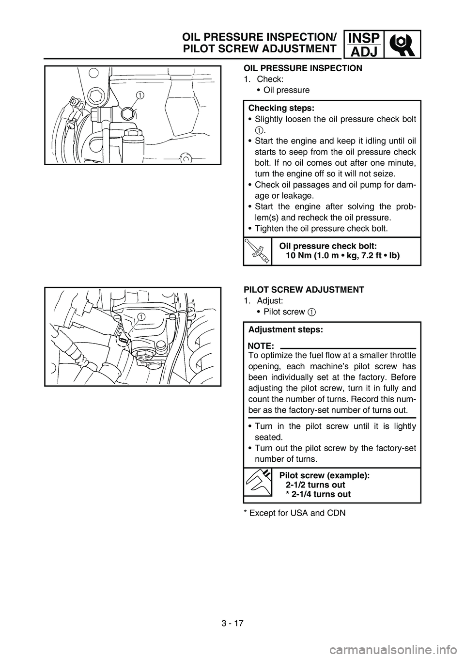
OIL PRESSURE INSPECTION
1. Check:
Oil pressure
Checking steps:
Slightly loosen the oil pressure check bolt
1.
Start the engine and keep it idling until oil
starts to seep from the oil pressure check
bolt. If no oil comes out after one minute,
turn the engine off so it will not seize.
Check oil passages and oil pump for dam-
age or leakage.
Start the engine after solving the prob-
lem(s) and recheck the oil pressure.
Tighten the oil pressure check bolt.
T R..
Oil pressure check bolt:
10 Nm (1.0 m kg, 7.2 ft lb)
PILOT SCREW ADJUSTMENT
1. Adjust:
Pilot screw 1
* Except for USA and CDNAdjustment steps:
NOTE:
To optimize the fuel flow at a smaller throttle
opening, each machine’s pilot screw has
been individually set at the factory. Before
adjusting the pilot screw, turn it in fully and
count the number of turns. Record this num-
ber as the factory-set number of turns out.
Turn in the pilot screw until it is lightly
seated.
Turn out the pilot screw by the factory-set
number of turns.
Pilot screw (example):
2-1/2 turns out
* 2-1/4 turns out
OIL PRESSURE INSPECTION/
PILOT SCREW ADJUSTMENT
Page 196 of 674
3 - 18
INSP
ADJ
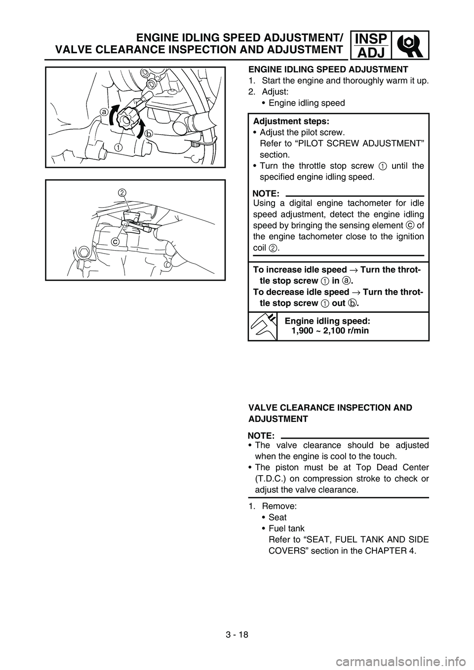
ENGINE IDLING SPEED ADJUSTMENT
1. Start the engine and thoroughly warm it up.
2. Adjust:
Engine idling speed
Adjustment steps:
Adjust the pilot screw.
Refer to “PILOT SCREW ADJUSTMENT”
section.
Turn the throttle stop screw 1 until the
specified engine idling speed.
NOTE:
Using a digital engine tachometer for idle
speed adjustment, detect the engine idling
speed by bringing the sensing element c of
the engine tachometer close to the ignition
coil 2.
To increase idle speed → Turn the throt-
tle stop screw 1 in a.
To decrease idle speed → Turn the throt-
tle stop screw 1 out b.
Engine idling speed:
1,900 ~ 2,100 r/min
c2
VALVE CLEARANCE INSPECTION AND
ADJUSTMENT
NOTE:
The valve clearance should be adjusted
when the engine is cool to the touch.
The piston must be at Top Dead Center
(T.D.C.) on compression stroke to check or
adjust the valve clearance.
1. Remove:
Seat
Fuel tank
Refer to “SEAT, FUEL TANK AND SIDE
COVERS” section in the CHAPTER 4.
ENGINE IDLING SPEED ADJUSTMENT/
VALVE CLEARANCE INSPECTION AND ADJUSTMENT
Page 246 of 674
3 - 42
INSP
ADJ
STEERING HEAD INSPECTION AND ADJUSTMENT
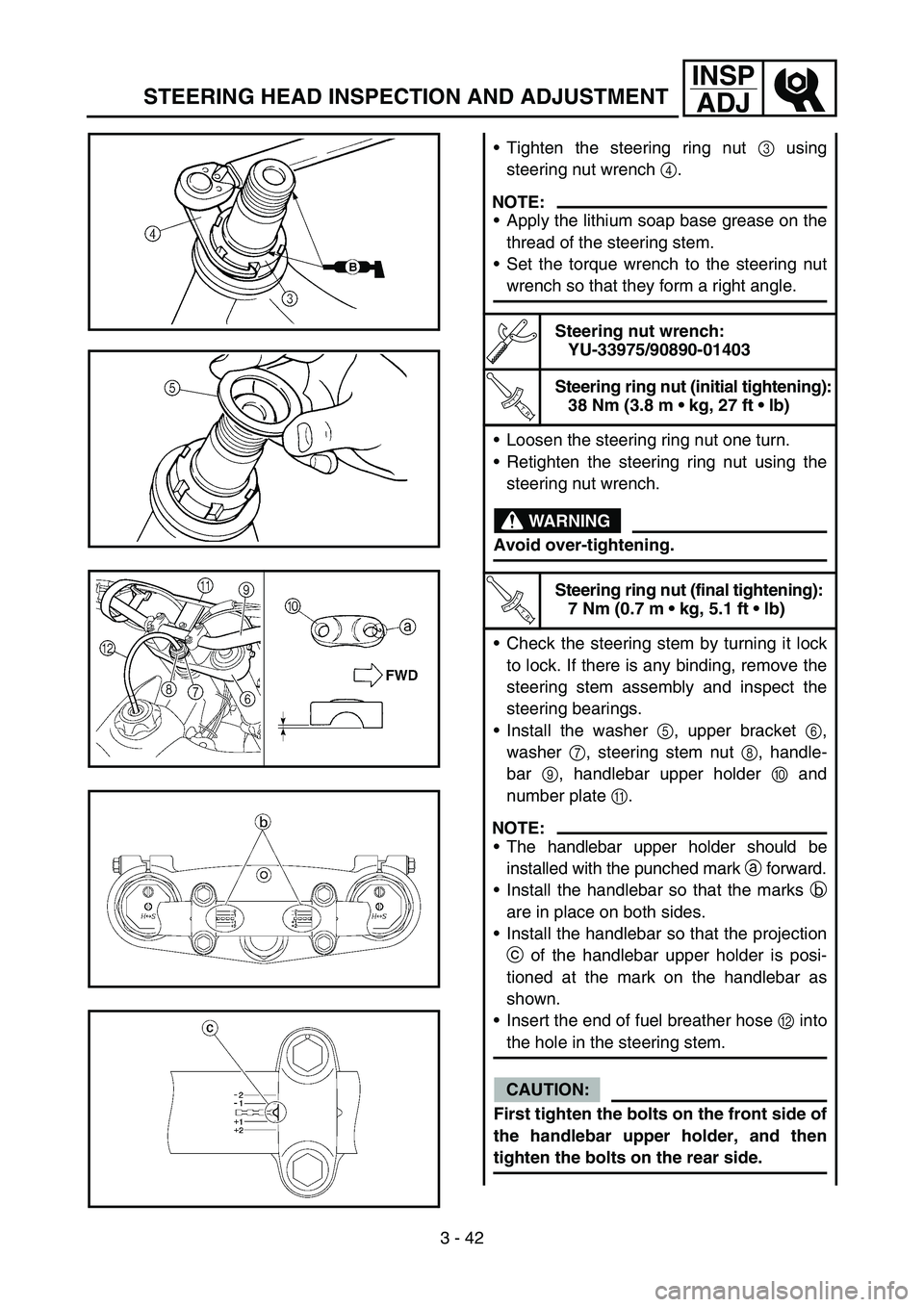
Tighten the steering ring nut 3 using
steering nut wrench 4.
NOTE:
Apply the lithium soap base grease on the
thread of the steering stem.
Set the torque wrench to the steering nut
wrench so that they form a right angle.
Steering nut wrench:
YU-33975/90890-01403
T R..
Steering ring nut (initial tightening):
38 Nm (3.8 m kg, 27 ft lb)
Loosen the steering ring nut one turn.
Retighten the steering ring nut using the
steering nut wrench.
WARNING
Avoid over-tightening.
T R..
Steering ring nut (final tightening):
7 Nm (0.7 m kg, 5.1 ft lb)
Check the steering stem by turning it lock
to lock. If there is any binding, remove the
steering stem assembly and inspect the
steering bearings.
Install the washer 5, upper bracket 6,
washer 7, steering stem nut 8, handle-
bar 9, handlebar upper holder 0 and
number plate A.
NOTE:
The handlebar upper holder should be
installed with the punched mark a forward.
Install the handlebar so that the marks b
are in place on both sides.
Install the handlebar so that the projection
c of the handlebar upper holder is posi-
tioned at the mark on the handlebar as
shown.
Insert the end of fuel breather hose B into
the hole in the steering stem.
CAUTION:
First tighten the bolts on the front side of
the handlebar upper holder, and then
tighten the bolts on the rear side.
Page 256 of 674
4 - 1
ENG
EC400000
ENGINE
SEAT, FUEL TANK AND SIDE COVERS
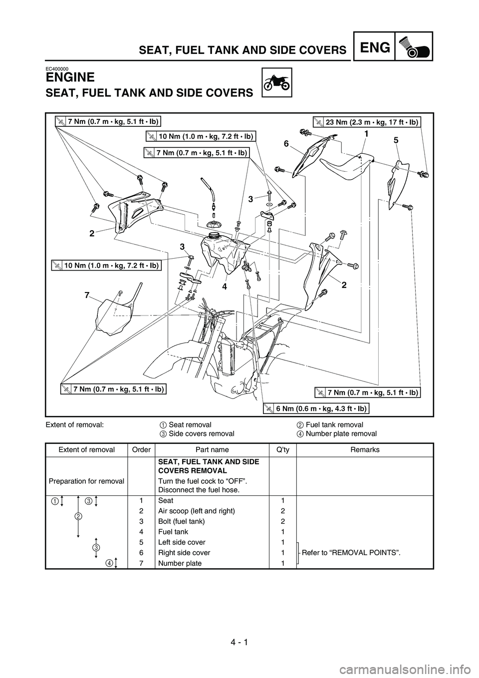
Extent of removal:
1 Seat removal
2 Fuel tank removal
3 Side covers removal
4 Number plate removal
Extent of removal Order Part name Q’ty Remarks
SEAT, FUEL TANK AND SIDE
COVERS REMOVAL
Preparation for removal Turn the fuel cock to “OFF”.
Disconnect the fuel hose.
1Seat 1
2 Air scoop (left and right) 2
3 Bolt (fuel tank) 2
4 Fuel tank 1
5 Left side cover 1
Refer to “REMOVAL POINTS”. 6 Right side cover 1
7 Number plate 1
4
2
1
3
3
SEAT, FUEL TANK AND SIDE COVERS
4
Page 258 of 674
4 - 2
ENG
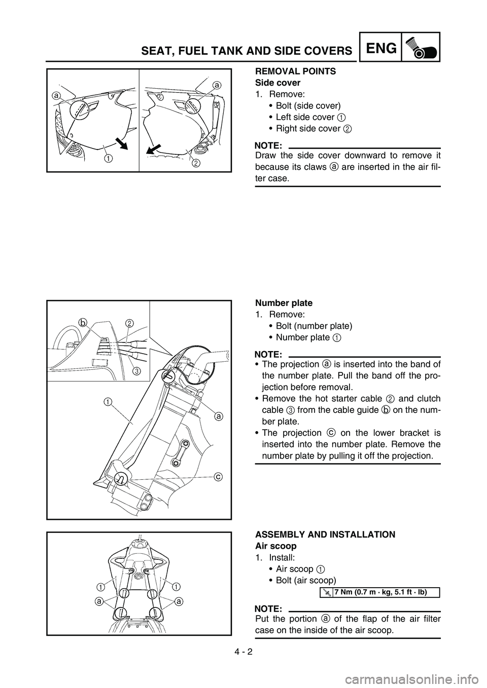
REMOVAL POINTS
Side cover
1. Remove:
Bolt (side cover)
Left side cover 1
Right side cover 2
NOTE:
Draw the side cover downward to remove it
because its claws a are inserted in the air fil-
ter case.
Number plate
1. Remove:
Bolt (number plate)
Number plate 1
NOTE:
The projection a is inserted into the band of
the number plate. Pull the band off the pro-
jection before removal.
Remove the hot starter cable 2 and clutch
cable 3 from the cable guide b on the num-
ber plate.
The projection c on the lower bracket is
inserted into the number plate. Remove the
number plate by pulling it off the projection.
ASSEMBLY AND INSTALLATION
Air scoop
1. Install:
Air scoop 1
Bolt (air scoop)
NOTE:
Put the portion a of the flap of the air filter
case on the inside of the air scoop.
T R..7 Nm (0.7 m · kg, 5.1 ft · lb)
SEAT, FUEL TANK AND SIDE COVERS
Page 260 of 674
4 - 3
ENGEXHAUST PIPE AND SILENCER
EC4S0000
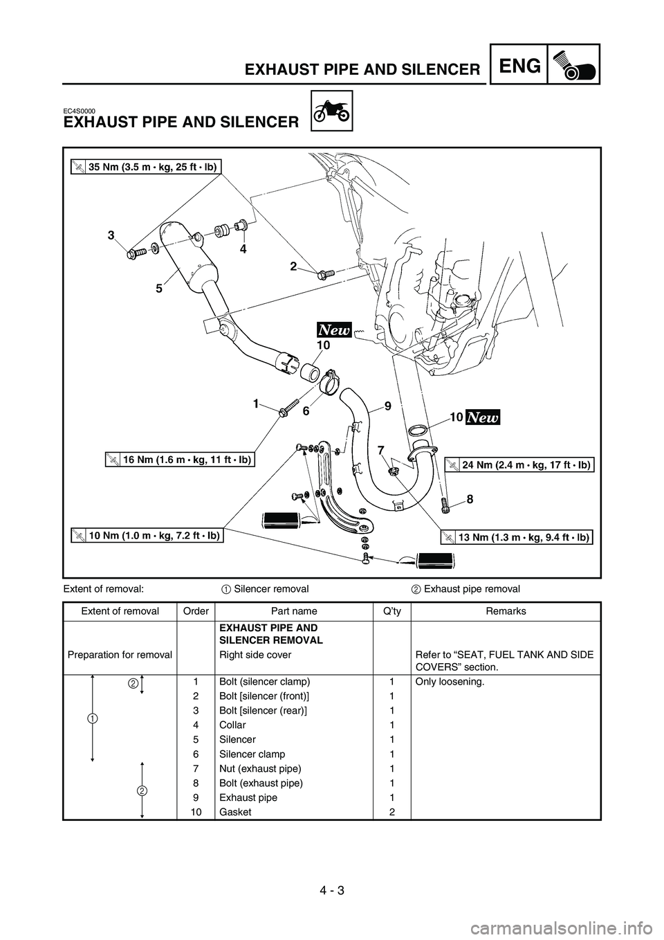
EXHAUST PIPE AND SILENCER
Extent of removal:
1 Silencer removal
2 Exhaust pipe removal
Extent of removal Order Part name Q’ty Remarks
EXHAUST PIPE AND
SILENCER REMOVAL
Preparation for removal Right side cover Refer to “SEAT, FUEL TANK AND SIDE
COVERS” section.
1 Bolt (silencer clamp) 1 Only loosening.
2 Bolt [silencer (front)] 1
3 Bolt [silencer (rear)] 1
4 Collar 1
5 Silencer 1
6 Silencer clamp 1
7 Nut (exhaust pipe) 1
8 Bolt (exhaust pipe) 1
9 Exhaust pipe 1
10 Gasket 2
2
1
2
Page 266 of 674
4 - 6
ENGRADIATOR
EC450001
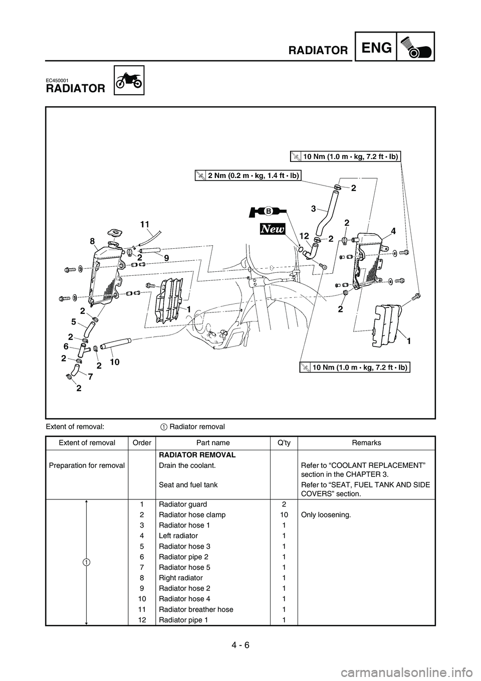
RADIATOR
Extent of removal:
1 Radiator removal
Extent of removal Order Part name Q’ty Remarks
RADIATOR REMOVAL
Preparation for removal Drain the coolant. Refer to “COOLANT REPLACEMENT”
section in the CHAPTER 3.
Seat and fuel tank Refer to “SEAT, FUEL TANK AND SIDE
COVERS” section.
1 Radiator guard 2
2 Radiator hose clamp 10 Only loosening.
3 Radiator hose 1 1
4 Left radiator 1
5 Radiator hose 3 1
6 Radiator pipe 2 1
7 Radiator hose 5 1
8 Right radiator 1
9 Radiator hose 2 1
10 Radiator hose 4 1
11 Radiator breather hose 1
12 Radiator pipe 1 1
1
Page 272 of 674

4 - 9
ENGCARBURETOR
CARBURETOR
3
97
8
4
4
2
T R..3 Nm (0.3 m • kg, 2.2 ft • Ib)
T R..3 Nm (0.3 m • kg, 2.2 ft • Ib)
T R..4 Nm (0.4 m •
kg, 2.9 ft • Ib)
T R..4 Nm (0.4 m •
kg, 2.9 ft • Ib)
T R..2 Nm (0.2 m •
kg, 1.4 ft • Ib)
T R..11 Nm (1.1 m •
kg, 8.0 ft • Ib)
5 1
6
6
Extent of removal:
1 Carburetor removal
Extent of removal Order Part name Q’ty Remarks
CARBURETOR REMOVAL
Preparation for removal Seat and fuel tank Refer to “SEAT, FUEL TANK AND SIDE
COVERS” section.
1Clamp 1
2 Throttle position sensor lead cou-
pler1
3 Throttle cable cover 1
4 Throttle cable 2
5 Clamp (air filter joint) 1 Loosen the screw (air filter joint).
6 Clamp (carburetor joint) 2 Loosen the screws (carburetor joint).
7 Hot starter plunger 1
8 Carburetor assembly 1
9 Carburetor joint 1
1
Page 278 of 674

4 - 12
ENGCARBURETOR
HANDLING NOTE
CAUTION:
Do not loosen the screws (throttle position
sensor)
1 except when changing the throt-
tle position sensor due to failure because it
will cause a drop in engine performance.
1
REMOVAL POINTS
Pilot screw
1. Remove:
Pilot screw 1
NOTE:
To optimize the fuel flow at a small throttle
opening, each machine’s pilot screw has been
individually set at the factory. Before removing
the pilot screw, turn it in fully and count the
number of turns. Record this number as the
factory-set number of turns out.
INSPECTION
Carburetor
1. Inspect:
Carburetor body
Contamination → Clean.
NOTE:
Use a petroleum based solvent for cleaning.
Blow out all passages and jets with com-
pressed air.
Never use a wire.
Page 298 of 674
4 - 22
ENGCAMSHAFTS
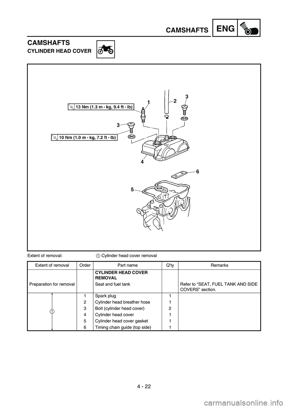
CAMSHAFTS
CYLINDER HEAD COVER
Extent of removal:
1 Cylinder head cover removal
Extent of removal Order Part name Q’ty Remarks
CYLINDER HEAD COVER
REMOVAL
Preparation for removal Seat and fuel tank Refer to “SEAT, FUEL TANK AND SIDE
COVERS” section.
1 Spark plug 1
2 Cylinder head breather hose 1
3 Bolt (cylinder head cover) 2
4 Cylinder head cover 1
5 Cylinder head cover gasket 1
6 Timing chain guide (top side) 1
1