THROTTLE CABLE YAMAHA YZ250F 2006 User Guide
[x] Cancel search | Manufacturer: YAMAHA, Model Year: 2006, Model line: YZ250F, Model: YAMAHA YZ250F 2006Pages: 674, PDF Size: 21.07 MB
Page 250 of 674

3 - 44
INSP
ADJ
LUBRICATION
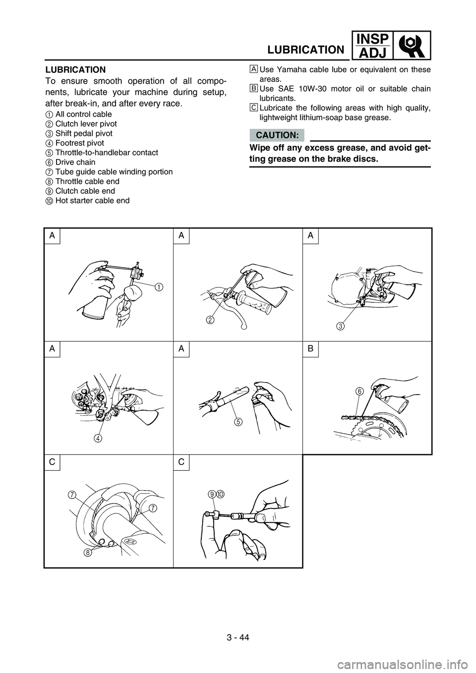
LUBRICATION
To ensure smooth operation of all compo-
nents, lubricate your machine during setup,
after break-in, and after every race.
1All control cable
2Clutch lever pivot
3Shift pedal pivot
4Footrest pivot
5Throttle-to-handlebar contact
6Drive chain
7Tube guide cable winding portion
8Throttle cable end
9Clutch cable end
0Hot starter cable end
ÈUse Yamaha cable lube or equivalent on these
areas.
ÉUse SAE 10W-30 motor oil or suitable chain
lubricants.
ÊLubricate the following areas with high quality,
lightweight lithium-soap base grease.
CAUTION:
Wipe off any excess grease, and avoid get-
ting grease on the brake discs.
AAA
AAB
CC
Page 272 of 674

4 - 9
ENGCARBURETOR
CARBURETOR
3
97
8
4
4
2
T R..3 Nm (0.3 m • kg, 2.2 ft • Ib)
T R..3 Nm (0.3 m • kg, 2.2 ft • Ib)
T R..4 Nm (0.4 m •
kg, 2.9 ft • Ib)
T R..4 Nm (0.4 m •
kg, 2.9 ft • Ib)
T R..2 Nm (0.2 m •
kg, 1.4 ft • Ib)
T R..11 Nm (1.1 m •
kg, 8.0 ft • Ib)
5 1
6
6
Extent of removal:
1 Carburetor removal
Extent of removal Order Part name Q’ty Remarks
CARBURETOR REMOVAL
Preparation for removal Seat and fuel tank Refer to “SEAT, FUEL TANK AND SIDE
COVERS” section.
1Clamp 1
2 Throttle position sensor lead cou-
pler1
3 Throttle cable cover 1
4 Throttle cable 2
5 Clamp (air filter joint) 1 Loosen the screw (air filter joint).
6 Clamp (carburetor joint) 2 Loosen the screws (carburetor joint).
7 Hot starter plunger 1
8 Carburetor assembly 1
9 Carburetor joint 1
1
Page 290 of 674

4 - 18
ENGCARBURETOR
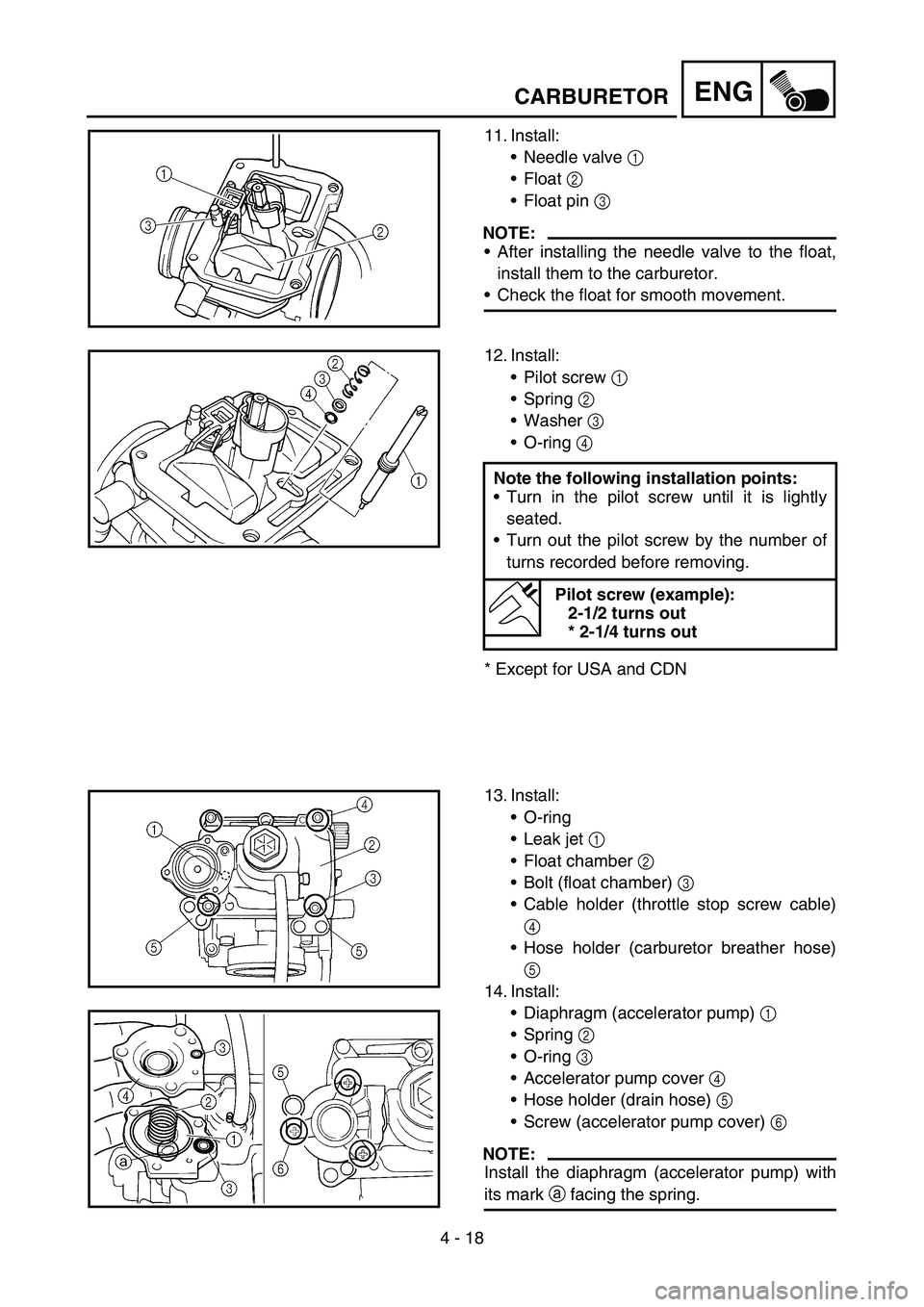
11. Install:
Needle valve 1
Float 2
Float pin 3
NOTE:
After installing the needle valve to the float,
install them to the carburetor.
Check the float for smooth movement.
12. Install:
Pilot screw 1
Spring 2
Washer 3
O-ring 4
* Except for USA and CDNNote the following installation points:
Turn in the pilot screw until it is lightly
seated.
Turn out the pilot screw by the number of
turns recorded before removing.
Pilot screw (example):
2-1/2 turns out
* 2-1/4 turns out
13. Install:
O-ring
Leak jet 1
Float chamber 2
Bolt (float chamber) 3
Cable holder (throttle stop screw cable)
4
Hose holder (carburetor breather hose)
5
14. Install:
Diaphragm (accelerator pump) 1
Spring 2
O-ring 3
Accelerator pump cover 4
Hose holder (drain hose) 5
Screw (accelerator pump cover) 6
NOTE:
Install the diaphragm (accelerator pump) with
its mark a facing the spring.
Page 296 of 674

4 - 21
ENG
3. Install:
Hot starter plunger 1
1T R..2 Nm (0.2 m · kg, 1.4 ft · lb)
4. Tighten:
Bolt (air filter joint) 1
Bolt (carburetor joint) 2
2
1
T R..3 Nm (0.3 m · kg, 2.2 ft · lb)
T R..3 Nm (0.3 m · kg, 2.2 ft · lb)
5. Install:
Throttle cable (pull) 1
Throttle cable (return) 2
6. Adjust:
Throttle grip free play
Refer to “THROTTLE CABLE ADJUST-
MENT” section in the CHAPTER 3.2
1
T R..4 Nm (0.4 m · kg, 2.9 ft · lb)
T R..11 Nm (1.1 m · kg, 8.0 ft · lb)
7. Install:
Throttle cable cover 1
Bolt (throttle cable cover) 2
2 1
T R..4 Nm (0.4 m · kg, 2.9 ft · lb)
8. Install:
Throttle position sensor lead coupler 1
Clamp 2
Refer to “CABLE ROUTING DIAGRAM”
section in the CHAPTER 2.
1
2
CARBURETOR
Page 544 of 674

5 - 43
CHASHANDLEBAR
EC5B0000
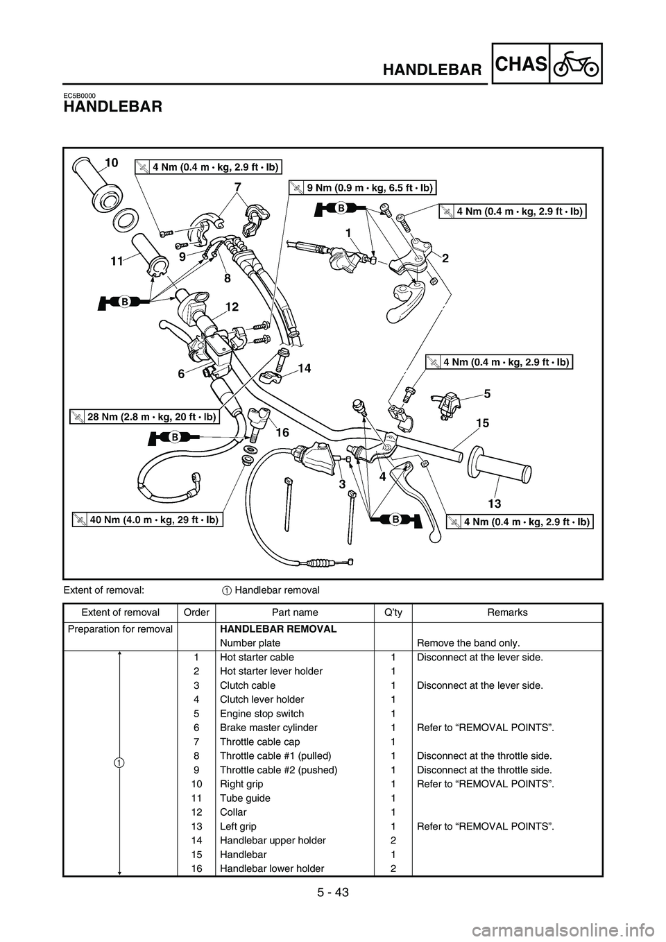
HANDLEBAR
Extent of removal:
1 Handlebar removal
Extent of removal Order Part name Q’ty Remarks
Preparation for removal
HANDLEBAR REMOVAL
Number plate Remove the band only.
1 Hot starter cable 1 Disconnect at the lever side.
2 Hot starter lever holder 1
3 Clutch cable 1 Disconnect at the lever side.
4 Clutch lever holder 1
5 Engine stop switch 1
6 Brake master cylinder 1 Refer to “REMOVAL POINTS”.
7 Throttle cable cap 1
8 Throttle cable #1 (pulled) 1 Disconnect at the throttle side.
9 Throttle cable #2 (pushed) 1 Disconnect at the throttle side.
10 Right grip 1 Refer to “REMOVAL POINTS”.
11 Tube guide 1
12 Collar 1
13 Left grip 1 Refer to “REMOVAL POINTS”.
14 Handlebar upper holder 2
15 Handlebar 1
16 Handlebar lower holder 2
1
Page 552 of 674

5 - 47
CHASHANDLEBAR
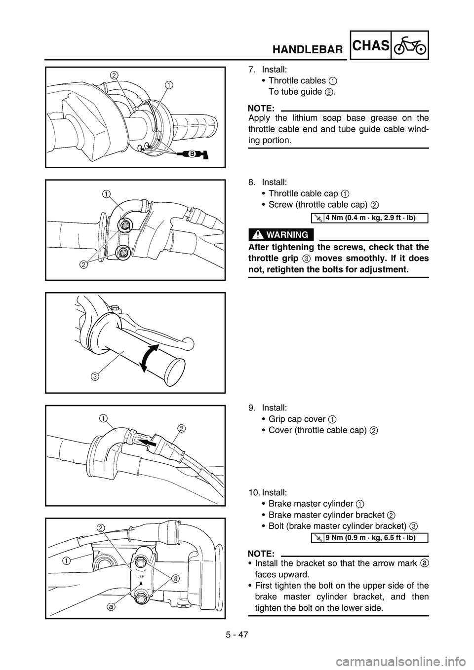
7. Install:
•Throttle cables 1
To tube guide 2.
NOTE:
Apply the lithium soap base grease on the
throttle cable end and tube guide cable wind-
ing portion.
8. Install:
•Throttle cable cap 1
•Screw (throttle cable cap) 2
WARNING
After tightening the screws, check that the
throttle grip
3 moves smoothly. If it does
not, retighten the bolts for adjustment.
T R..4 Nm (0.4 m · kg, 2.9 ft · lb)
9. Install:
•Grip cap cover 1
•Cover (throttle cable cap) 2
10. Install:
•Brake master cylinder 1
•Brake master cylinder bracket 2
•Bolt (brake master cylinder bracket) 3
NOTE:
•Install the bracket so that the arrow mark a
faces upward.
•First tighten the bolt on the upper side of the
brake master cylinder bracket, and then
tighten the bolt on the lower side.
T R..9 Nm (0.9 m · kg, 6.5 ft · lb)