Carburetor YAMAHA YZ250F 2006 Owners Manual
[x] Cancel search | Manufacturer: YAMAHA, Model Year: 2006, Model line: YZ250F, Model: YAMAHA YZ250F 2006Pages: 674, PDF Size: 21.07 MB
Page 8 of 674
6. GASOLINE CAN CAUSE INJURY.
If you should swallow some gasoline,
inhale excess gasoline vapors, or
allow any gasoline to get into your
eyes, contact a doctor immediately. If
any gasoline spills onto your skin or
clothing, immediately wash skin
areas with soap and water, and
change your clothes.
7. ONLY OPERATE THE MACHINE IN AN
AREA WITH ADEQUATE VENTILA-
TION.
Never start the engine or let it run for
any length of time in an enclosed
area. Exhaust fumes are poisonous.
These fumes contain carbon monox-
ide, which by itself is odorless and
colorless. Carbon monoxide is a dan-
gerous gas which can cause uncon-
sciousness or can be lethal.
8. PARK THE MACHINE CAREFULLY;
TURN OFF THE ENGINE.
Always turn off the engine if you are
going to leave the machine. Do not
park the machine on a slope or soft
ground as it may fall over.
9. THE ENGINE, EXHAUST PIPE, MUF-
FLER, AND OIL TANK WILL BE VERY
HOT AFTER THE ENGINE HAS BEEN
RUN.
Be careful not to touch them or to
allow any clothing item to contact
them during inspection or repair.
10. PROPERLY SECURE THE MACHINE
BEFORE TRANSPORTING IT.
When transporting the machine in
another vehicle, always be sure it is
properly secured and in an upright
position and that the fuel cock is in
the “OFF” position. Otherwise, fuel
may leak out of the carburetor or fuel
tank.
Page 22 of 674
CHAPTER 4
ENGINE
SEAT, FUEL TANK
AND SIDE COVERS...................................4-1
EXHAUST PIPE AND SILENCER..............4-3
RADIATOR.................................................4-6
CARBURETOR...........................................4-9
CAMSHAFTS............................................4-22
CYLINDER HEAD.....................................4-31
VALVES AND VALVE SPRINGS.............4-34
CYLINDER AND PISTON.........................4-43
CLUTCH....................................................4-50
OIL FILTER ELEMENT, WATER PUMP
AND RIGHT CRANKCASE COVER........4-57
BALANCER..............................................4-64
OIL PUMP.................................................4-67
KICK SHAFT AND SHIFT SHAFT...........4-73
CDI MAGNETO.........................................4-80
ENGINE REMOVAL..................................4-84
CRANKCASE AND CRANKSHAFT.........4-89
TRANSMISSION, SHIFT CAM
AND SHIFT FORK....................................4-98
CHAPTER 5
CHASSIS
FRONT WHEEL AND REAR WHEEL........5-1
FRONT BRAKE AND REAR BRAKE......5-10
FRONT FORK...........................................5-26
HANDLEBAR............................................5-43
STEERING................................................5-49
SWINGARM..............................................5-54
REAR SHOCK ABSORBER.....................5-62
Page 52 of 674

1 - 11
GEN
INFO
CONTROL FUNCTIONS
EC156000
FRONT BRAKE LEVER
The front brake lever 1 is located on the right
handlebar. Pull it toward the handlebar to acti-
vate the front brake.
EC157000
REAR BRAKE PEDAL
The rear brake pedal 1 is located on the right
side of the machine. Press down on the brake
pedal to activate the rear brake.
EC158001
FUEL COCK
The fuel cock supplies fuel from the tank to
carburetor while filtering the fuel. The fuel cock
has the two positions:
OFF: With the lever in this position, fuel will not
flow. Always return the lever to this posi-
tion when the engine is not running.
ON: With the lever in this position, fuel flows
to the carburetor. Normal riding is done
with the lever in this position.
COLD STARTER KNOB
When cold, the engine requires a richer air-fuel
mixture for starting. A separate starter circuit,
which is controlled by the cold starter knob 1,
supplies this mixture. Pull the cold starter knob
out to open the circuit for starting. When the
engine has warmed up, push it in to close the
circuit.
1
HOT STARTER LEVER
The hot starter lever 1 is used when starting a
warm engine.
Use the hot starter lever when starting the
engine again immediately after it was stopped
(the engine is still warm). Pulling the hot starter
lever injects secondary air to thin the air-fuel
mixture temporarily, allowing the engine to be
started more easily.
Page 54 of 674
1 - 12
GEN
INFO
CONTROL FUNCTIONS
EC15R001
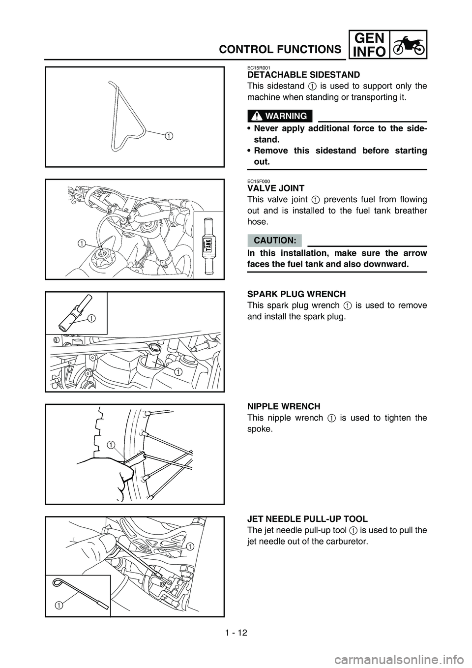
DETACHABLE SIDESTAND
This sidestand 1 is used to support only the
machine when standing or transporting it.
WARNING
Never apply additional force to the side-
stand.
Remove this sidestand before starting
out.
EC15F000
VALVE JOINT
This valve joint 1 prevents fuel from flowing
out and is installed to the fuel tank breather
hose.
CAUTION:
In this installation, make sure the arrow
faces the fuel tank and also downward.
SPARK PLUG WRENCH
This spark plug wrench 1 is used to remove
and install the spark plug.
1
1
NIPPLE WRENCH
This nipple wrench 1 is used to tighten the
spoke.
JET NEEDLE PULL-UP TOOL
The jet needle pull-up tool 1 is used to pull the
jet needle out of the carburetor.
1
1
Page 58 of 674

1 - 14
GEN
INFO
STARTING AND BREAK-IN
WARNING
Never start or run the engine in a closed
area. The exhaust fumes are poisonous;
they can cause loss of consciousness and
death in a very short time. Always operate
the machine in a well-ventilated area.
CAUTION:
The carburetor on this machine has a
built-in accelerator pump. Therefore,
when starting the engine, do not operate
the throttle or the spark plug will foul.
Unlike a two-stroke engine, this engine
cannot be kick started when the throttle is
open because the kick starter may kick
back. Also, if the throttle is open the air/
fuel mixture may be too lean for the
engine to start.
Before starting the machine, perform the
checks in the pre-operation check list.
STARTING A COLD ENGINE
1. Inspect the coolant level.
2. Turn the fuel cock to “ON”.
3. Shift the transmission into neutral.
4. Fully open the cold starter knob 1.
5. Kick the kickstarter crank.
WARNING
Do not open the throttle while kicking the
kickstarter crank. Otherwise, the kick-
starter may kick back.
1
STARTING AND BREAK-IN
Page 75 of 674
SPEC
2 - 2 Oil type or grade:
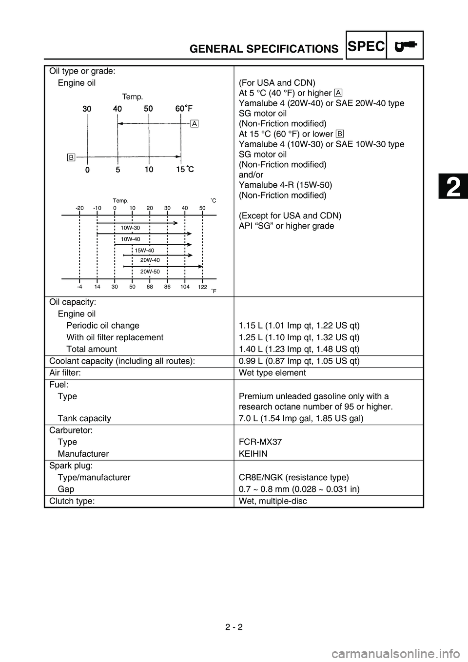
Engine oil (For USA and CDN)
At 5 °C (40 °F) or higher È
Yamalube 4 (20W-40) or SAE 20W-40 type
SG motor oil
(Non-Friction modified)
At 15 °C (60 °F) or lower É
Yamalube 4 (10W-30) or SAE 10W-30 type
SG motor oil
(Non-Friction modified)
and/or
Yamalube 4-R (15W-50)
(Non-Friction modified)
(Except for USA and CDN)
API “SG” or higher grade
Oil capacity:
Engine oil
Periodic oil change 1.15 L (1.01 Imp qt, 1.22 US qt)
With oil filter replacement 1.25 L (1.10 Imp qt, 1.32 US qt)
Total amount 1.40 L (1.23 Imp qt, 1.48 US qt)
Coolant capacity (including all routes): 0.99 L (0.87 Imp qt, 1.05 US qt)
Air filter: Wet type element
Fuel:
Type Premium unleaded gasoline only with a
research octane number of 95 or higher.
Tank capacity 7.0 L (1.54 Imp gal, 1.85 US gal)
Carburetor:
Type FCR-MX37
Manufacturer KEIHIN
Spark plug:
Type/manufacturer CR8E/NGK (resistance type)
Gap 0.7 ~ 0.8 mm (0.028 ~ 0.031 in)
Clutch type: Wet, multiple-disc
-20
-4-10
140
3010
5020
6830
8640 50
104
122 ˚CTemp.
˚F
10W-30
10W-40
20W-40
20W-50
15W-40
GENERAL SPECIFICATIONS
2
Page 81 of 674
SPEC
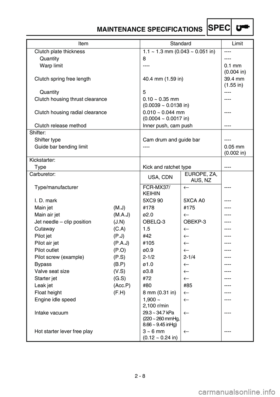
2 - 8 Clutch plate thickness 1.1 ~ 1.3 mm (0.043 ~ 0.051 in) ----
Quantity 8 ----
Warp limit ---- 0.1 mm
(0.004 in)
Clutch spring free length 40.4 mm (1.59 in) 39.4 mm
(1.55 in)
Quantity 5 ----
Clutch housing thrust clearance 0.10 ~ 0.35 mm
(0.0039 ~ 0.0138 in)----
Clutch housing radial clearance 0.010 ~ 0.044 mm
(0.0004 ~ 0.0017 in)----
Clutch release method Inner push, cam push ----
Shifter:
Shifter type Cam drum and guide bar ----
Guide bar bending limit ---- 0.05 mm
(0.002 in)
Kickstarter:
Type Kick and ratchet type ----
Carburetor:
USA, CDNEUROPE, ZA,
AUS, NZ
Type/manufacturer FCR-MX37/
KEIHIN
←----
I. D. mark 5XC9 90 5XCA A0 ----
Main jet (M.J) #178 #175 ----
Main air jet (M.A.J)ø2.0
←----
Jet needle – clip position (J.N) OBELQ-3 OBEKP-3 ----
Cutaway (C.A) 1.5
←----
Pilot jet (P.J) #42
←----
Pilot air jet (P.A.J) #105
←----
Pilot outlet (P.O)ø0.9
←----
Pilot screw (example) (P.S) 2-1/2 2-1/4 ----
Bypass (B.P)ø1.0
←----
Valve seat size (V.S)ø3.8
←----
Starter jet (G.S) #72
←----
Leak jet (Acc.P) #80 #85 ----
Float height (F.H) 8 mm (0.31 in)
←----
Engine idle speed 1,900 ~
2,100 r/min
←----
Intake vacuum
29.3 ~ 34.7 kPa
(220 ~ 260 mmHg,
8.66 ~ 9.45 inHg)←----
Hot starter lever free play 3 ~ 6 mm
(0.12 ~ 0.24 in)
←---- Item Standard Limit
MAINTENANCE SPECIFICATIONS
Page 83 of 674
SPEC
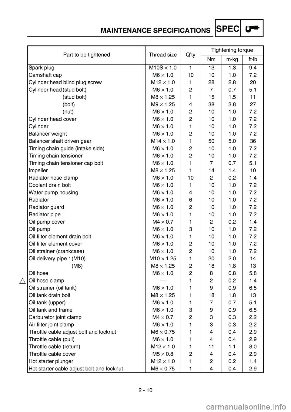
2 - 10 Part to be tightened Thread size Q’tyTightening torque
Nm m·kg ft·lb
Spark plug M10S × 1.0 1 13 1.3 9.4
Camshaft cap M6 × 1.0 10 10 1.0 7.2
Cylinder head blind plug screw M12 × 1.0 1 28 2.8 20
Cylinder head (stud bolt) M6 × 1.0 2 7 0.7 5.1
(stud bolt) M8 × 1.25 1 15 1.5 11
(bolt) M9 × 1.25 4 38 3.8 27
(nut) M6 × 1.0 2 10 1.0 7.2
Cylinder head cover M6 × 1.0 2 10 1.0 7.2
Cylinder M6 × 1.0 1 10 1.0 7.2
Balancer weight M6 × 1.0 2 10 1.0 7.2
Balancer shaft driven gear M14 × 1.0 1 50 5.0 36
Timing chain guide (intake side) M6 × 1.0 2 10 1.0 7.2
Timing chain tensioner M6 × 1.0 2 10 1.0 7.2
Timing chain tensioner cap bolt M6 × 1.0 1 7 0.7 5.1
Impeller M8 × 1.25 1 14 1.4 10
Radiator hose clamp M6 × 1.0 10 2 0.2 1.4
Coolant drain bolt M6 × 1.0 1 10 1.0 7.2
Water pump housing M6 × 1.0 4 10 1.0 7.2
Radiator M6 × 1.0 6 10 1.0 7.2
Radiator guard M6 × 1.0 2 10 1.0 7.2
Radiator pipe M6 × 1.0 1 10 1.0 7.2
Oil pump cover M4 × 0.7 1 2 0.2 1.4
Oil pump M6 × 1.0 3 10 1.0 7.2
Oil filter element drain bolt M6 × 1.0 1 10 1.0 7.2
Oil filter element cover M6 × 1.0 2 10 1.0 7.2
Oil strainer (crankcase) M6 × 1.0 2 10 1.0 7.2
Oil delivery pipe 1 (M10) M10 × 1.25 1 20 2.0 14
(M8) M8 × 1.25 2 18 1.8 13
Oil hose M6 × 1.0 2 8 0.8 5.8
Oil hose clamp—120.21.4
Oil strainer (oil tank) M6 × 1.0 1 9 0.9 6.5
Oil tank drain bolt M8 × 1.25 1 18 1.8 13
Oil tank (upper) M6 × 1.0 1 7 0.7 5.1
Oil tank and frame M6 × 1.0 3 9 0.9 6.5
Carburetor joint clamp M4 × 0.7 2 3 0.3 2.2
Air filter joint clamp M6 × 1.0 1 3 0.3 2.2
Throttle cable adjust bolt and locknut M6 × 0.75 1 4 0.4 2.9
Throttle cable (pull) M6 × 1.0 1 4 0.4 2.9
Throttle cable (return) M12 × 1.0 1 11 1.1 8.0
Throttle cable cover M5 × 0.8 2 4 0.4 2.9
Hot starter plunger M12 × 1.0 1 2 0.2 1.4
Hot starter cable adjust bolt and locknut M6 × 0.75 1 4 0.4 2.9
MAINTENANCE SPECIFICATIONS
Page 142 of 674

2 - 18
SPECCABLE ROUTING DIAGRAM
EC240000
CABLE ROUTING DIAGRAM
1Fuel tank breather hose
2Radiator hose 1
3Cylinder head breather hose
4Radiator hose 4
5Clutch cable
6Throttle position sensor lead
7Fuel hose
8Hot starter cable
9Carburetor breather hose
0Carburetor overflow hose
AConnector coverÈInsert the end of the fuel tank
breather hose into the hole in
the steering stem.
ÉPass the cylinder head
breather hose on the outside of
the radiator hose 1 and on the
inside of the radiator pipe (radi-
ator hose 4).
ÊPass the clutch cable through
the cable guides.
ËPass the clutch cable in front of
the radiator mounting boss.ÌPass the fuel hose between the
hot starter cable and throttle
position sensor lead.
ÍPass the carburetor breather
hoses and overflow hose so
that all there hoses do not con-
tact the rear shock absorber.
ÎInstall the connector cover so
that it does not come in
between the radiator hose 1
and radiator.
B A
99
0
Í
B
A
8
3A2Î
7
Ì
ËÉ
1
È
6
5
4
Ê
Page 155 of 674
3 - 2
INSP
ADJ
MAINTENANCE INTERVALS
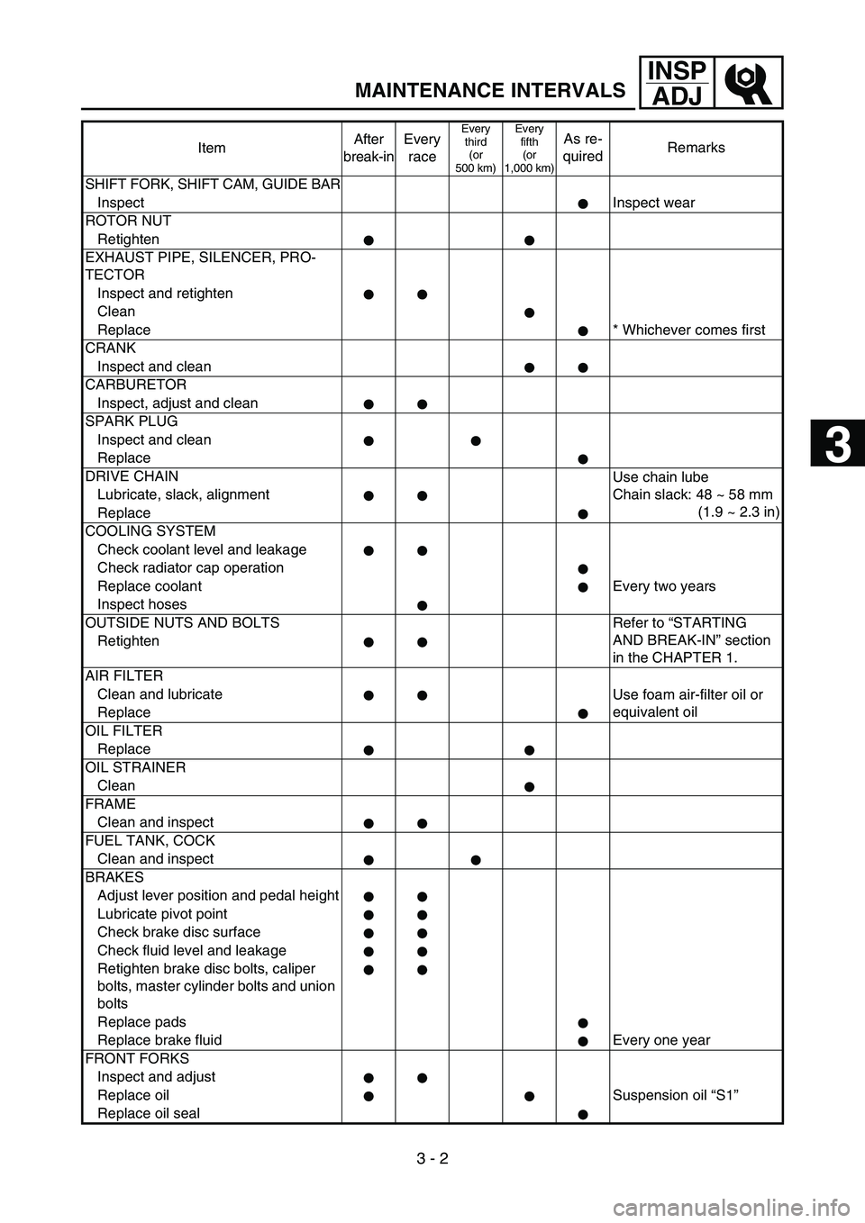
SHIFT FORK, SHIFT CAM, GUIDE BAR
InspectInspect wear
ROTOR NUT
Retighten
EXHAUST PIPE, SILENCER, PRO-
TECTOR
Inspect and retighten
Clean
Replace * Whichever comes first
CRANK
Inspect and clean
CARBURETOR
Inspect, adjust and clean
SPARK PLUG
Inspect and clean
Replace
DRIVE CHAIN
Use chain lube
Chain slack: 48 ~ 58 mm
(1.9 ~ 2.3 in) Lubricate, slack, alignment
Replace
COOLING SYSTEM
Check coolant level and leakage
Check radiator cap operation
Replace coolant Every two years
Inspect hoses
OUTSIDE NUTS AND BOLTS Refer to “STARTING
AND BREAK-IN” section
in the CHAPTER 1. Retighten
AIR FILTER
Clean and lubricate
Use foam air-filter oil or
equivalent oil
Replace
OIL FILTER
Replace
OIL STRAINER
Clean
FRAME
Clean and inspect
FUEL TANK, COCK
Clean and inspect
BRAKES
Adjust lever position and pedal height
Lubricate pivot point
Check brake disc surface
Check fluid level and leakage
Retighten brake disc bolts, caliper
bolts, master cylinder bolts and union
bolts
Replace pads
Replace brake fluid Every one year
FRONT FORKS
Inspect and adjust
Replace oil Suspension oil “S1”
Replace oil sealItemAfter
break-inEvery
race
Every
third
(or
500 km)Every
fifth
(or
1,000 km)As re-
quiredRemarks
3