bolt pattern YAMAHA YZ250F 2006 Owners Manual
[x] Cancel search | Manufacturer: YAMAHA, Model Year: 2006, Model line: YZ250F, Model: YAMAHA YZ250F 2006Pages: 674, PDF Size: 21.07 MB
Page 302 of 674

4 - 24
ENGCAMSHAFTS
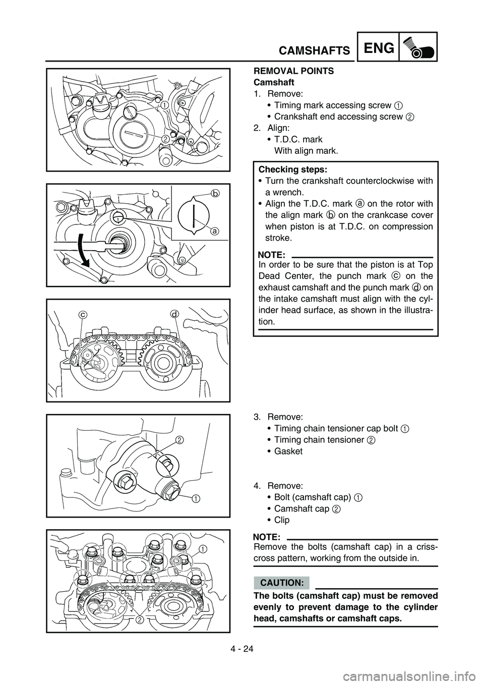
REMOVAL POINTS
Camshaft
1. Remove:
Timing mark accessing screw 1
Crankshaft end accessing screw 2
2. Align:
T.D.C. mark
With align mark.
Checking steps:
Turn the crankshaft counterclockwise with
a wrench.
Align the T.D.C. mark a on the rotor with
the align mark b on the crankcase cover
when piston is at T.D.C. on compression
stroke.
NOTE:
In order to be sure that the piston is at Top
Dead Center, the punch mark c on the
exhaust camshaft and the punch mark d on
the intake camshaft must align with the cyl-
inder head surface, as shown in the illustra-
tion.
3. Remove:
Timing chain tensioner cap bolt 1
Timing chain tensioner 2
Gasket
4. Remove:
Bolt (camshaft cap) 1
Camshaft cap 2
Clip
NOTE:
Remove the bolts (camshaft cap) in a criss-
cross pattern, working from the outside in.
CAUTION:
The bolts (camshaft cap) must be removed
evenly to prevent damage to the cylinder
head, camshafts or camshaft caps.
1
2
Page 306 of 674

4 - 26
ENGCAMSHAFTS
4. Measure:
Camshaft-to-cap clearance
Out of specification → Measure camshaft
outside diameter.
Camshaft-to-cap clearance:
0.028 ~ 0.062 mm
(0.0011 ~ 0.0024 in)
Measurement steps:
Install the camshaft onto the cylinder
head.
Position a strip of Plastigauge
® 1 onto the
camshaft.
Install the clip, dowel pins and camshaft
caps.
T R..
Bolt (camshaft cap):
10 Nm (1.0 m kg, 7.2 ft lb)
NOTE:
Tighten the bolts (camshaft cap) in a criss-
cross pattern from innermost to outer
caps.
Do not turn the camshaft when measuring
clearance with the Plastigauge®.
Remove the camshaft caps and measure
the width of the Plastigauge
® 1.
5. Measure:
Camshaft outside diameter a
Out of specification → Replace the cam-
shaft.
Within specification → Replace camshaft
case and camshaft caps as a set.
Camshaft sprocket
1. Inspect:
Camshaft sprocket 1
Wear/damage → Replace the camshaft
assembly and timing chain as a set.
Camshaft outside diameter:
21.959 ~ 21.972 mm
(0.8645 ~ 0.8650 in)
Page 310 of 674

4 - 28
ENGCAMSHAFTS
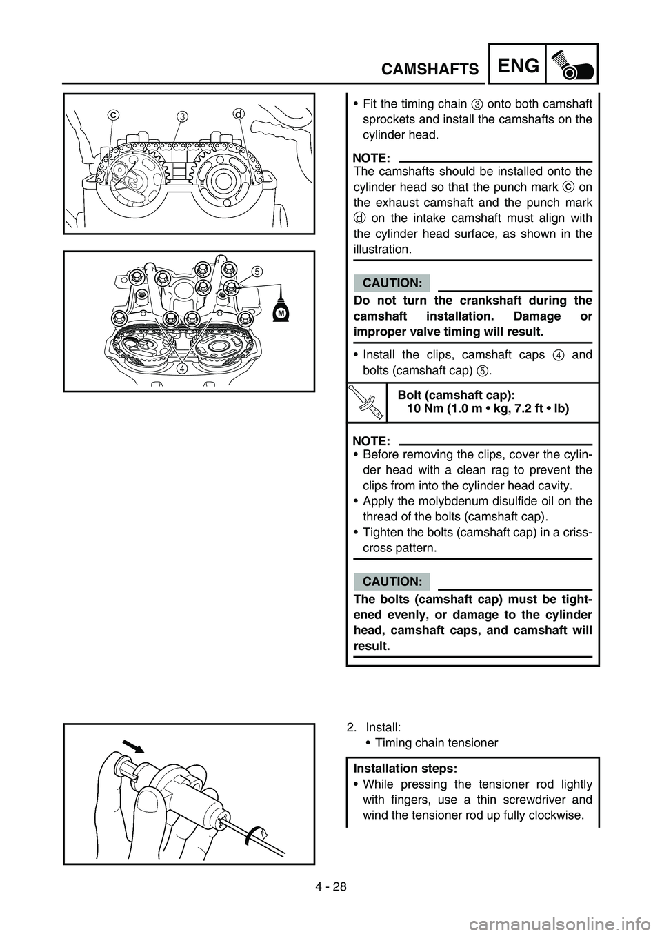
Fit the timing chain 3 onto both camshaft
sprockets and install the camshafts on the
cylinder head.
NOTE:
The camshafts should be installed onto the
cylinder head so that the punch mark c on
the exhaust camshaft and the punch mark
d on the intake camshaft must align with
the cylinder head surface, as shown in the
illustration.
CAUTION:
Do not turn the crankshaft during the
camshaft installation. Damage or
improper valve timing will result.
Install the clips, camshaft caps 4 and
bolts (camshaft cap) 5.
T R..
Bolt (camshaft cap):
10 Nm (1.0 m kg, 7.2 ft lb)
NOTE:
Before removing the clips, cover the cylin-
der head with a clean rag to prevent the
clips from into the cylinder head cavity.
Apply the molybdenum disulfide oil on the
thread of the bolts (camshaft cap).
Tighten the bolts (camshaft cap) in a criss-
cross pattern.
CAUTION:
The bolts (camshaft cap) must be tight-
ened evenly, or damage to the cylinder
head, camshaft caps, and camshaft will
result.
5
4
M
2. Install:
Timing chain tensioner
Installation steps:
While pressing the tensioner rod lightly
with fingers, use a thin screwdriver and
wind the tensioner rod up fully clockwise.
Page 366 of 674

4 - 56
ENGCLUTCH
7. Install:
Push rod 2 1
Ball 2
Push rod 1 3
NOTE:
Apply the engine oil on the push rod 1, 2 and
ball.
8. Install:
Pressure plate 1
9. Install:
Clutch spring 1
Bolt (clutch spring) 2
NOTE:
Tighten the bolts in stage, using a crisscross
pattern.
T R..10 Nm (1.0 m · kg, 7.2 ft · lb)
10. Install:
Dowel pin 1
Gasket (clutch cover) 2
11. Install:
Clutch cover 1
Bolt (clutch cover)
NOTE:
Tighten the bolts in stage, using a crisscross
pattern.
T R..10 Nm (1.0 m · kg, 7.2 ft · lb)
Page 378 of 674

4 - 62
ENG
OIL FILTER ELEMENT, WATER PUMP AND RIGHT
CRANKCASE COVER
2. Install:
Right crankcase cover 1
Bolt (right crankcase cover) 2
NOTE:
Apply the engine oil on the impeller shaft
end.
Mesh the impeller shaft gear 3 with primary
drive gear 4.
Tighten the bolts in stage, using a crisscross
pattern.
T R..10 Nm (1.0 m · kg, 7.2 ft · lb)
Kickstarter crank
1. Install:
Kickstarter crank 1
Washer 2
Bolt (kickstarter crank) 3
NOTE:
Install the kickstarter crank with the kickstarter
crank and frame 15 mm (0.59 in) or more apart
a and the kickstarter crank and right crank-
case 3 mm (0.12 in) or more apart b.
2. Install:
Oil hose 1
Bolt (oil hose) 2
ba
T R..33 Nm (3.3 m · kg, 24 ft · lb)
T R..8 Nm (0.8 m · kg, 5.8 ft · lb)
3. Install:
Copper washer 1
Oil delivery pipe 2
Union bolt (M8) 3
Union bolt (M10) 4
T R..18 Nm (1.8 m · kg, 13 ft · lb)
T R..20 Nm (2.0 m · kg, 14 ft · lb)
Page 420 of 674

4 - 83
ENGCDI MAGNETO
4. Connect:
CDI magneto lead
Refer to “CABLE ROUTING DIAGRAM”
section in the CHAPTER 2.
5. Install:
Dowel pin
Gasket (left crankcase cover)
Left crankcase cover 1
Hose guide (cylinder head breather hose)
2
Bolt (left crankcase cover)
NOTE:
Tighten the bolts in stage, using a crisscross
pattern.
2
1
T R..10 Nm (1.0 m · kg, 7.2 ft · lb)
Page 448 of 674

4 - 97
ENGCRANKCASE AND CRANKSHAFT
6. Tighten:
Hose guide 1
Clutch cable holder 2
Bolt (crankcase) 3
NOTE:
Tighten the crankcase tightening bolts in
stage, using a crisscross pattern.
T R..12 Nm (1.2 m · kg, 8.7 ft · lb)
7. Install:
Oil delivery pipe 2 1
O-ring 2
Bolt (oil delivery pipe 2) 3
NOTE:
Apply the lithium soap base grease on the O-
rings.
T R..10 Nm (1.0 m · kg, 7.2 ft · lb)
8. Install:
Timing chain 1
Timing chain guide (intake side) 2
Bolt (timing chain guide) 3
9. Remove:
Sealant
Forced out on the cylinder mating sur-
face.
10. Apply:
Engine oil
To the crank pin, bearing and oil delivery
hole.
11. Check:
Crankshaft and transmission operation.
Unsmooth operation → Repair.
T R..10 Nm (1.0 m · kg, 7.2 ft · lb)
Page 468 of 674

5 - 5
CHASFRONT WHEEL AND REAR WHEEL
EC595000
ASSEMBLY AND INSTALLATION
Front wheel
1. Install:
Bearing (left) 1
Spacer 2
Bearing (right) 3
Oil seal 4
NOTE:
Apply the lithium soap base grease on the
bearing and oil seal lip when installing.
Use a socket that matches the outside diam-
eter of the race of the bearing.
Left side of bearing shall be installed first.
Install the oil seal with its manufacture’s
marks or numbers facing outward.
CAUTION:
Do not strike the inner race of the bearing.
Contact should be made only with the outer
race.
2. Install:
Brake disc 1
Bolt (brake disc) 2
NOTE:
Tighten the bolts in stage, using a crisscross
pattern.
T R..12 Nm (1.2 m · kg, 8.7 ft · lb)
3. Install:
Collar 1
NOTE:
Apply the lithium soap base grease on the oil
seal lip.
Install the collars with their projections a
facing the wheel.
4. Install:
Wheel
NOTE:
Install the brake disc 1 between the brake
pads 2 correctly.
Page 472 of 674

5 - 7
CHASFRONT WHEEL AND REAR WHEEL
Rear wheel
1. Install:
Bearing (right) 1
Circlip 2
Spacer 3
Bearing (left) 4
Oil seal 5
NOTE:
Apply the lithium soap base grease on the
bearing and oil seal lip when installing.
Install the bearing with seal facing outward.
Use a socket that matches the outside diam-
eter of the race of the bearing.
Right side of bearing shall be installed first.
Install the oil seal with its manufacture’s
marks or numbers facing outward.
CAUTION:
Do not strike the inner race of the bearing.
Contact should be made only with the outer
race.
2. Install:
Brake disc 1
Bolt (brake disc) 2
NOTE:
Tighten the bolts in stage, using a crisscross
pattern.
T R..14 Nm (1.4 m · kg, 10 ft · lb)
3. Install:
Rear wheel sprocket 1
Bolt (rear wheel sprocket) 2
Washer (rear wheel sprocket) 3
Nut (rear wheel sprocket) 4
NOTE:
Tighten the nuts in stage, using a crisscross
pattern.
T R..42 Nm (4.2 m · kg, 30 ft · lb)