radiator cap YAMAHA YZ250F 2006 Owners Manual
[x] Cancel search | Manufacturer: YAMAHA, Model Year: 2006, Model line: YZ250F, Model: YAMAHA YZ250F 2006Pages: 674, PDF Size: 21.07 MB
Page 23 of 674
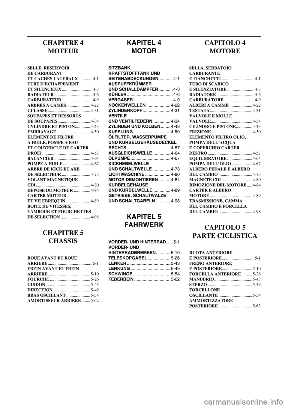
KAPITEL 4
MOTOR
SITZBANK,
KRAFTSTOFFTANK UND
SEITENABDECKUNGEN............ 4-1
AUSPUFFKRÜMMER
UND SCHALLDÄMPFER............ 4-3
KÜHLER...................................... 4-6
VERGASER................................. 4-9
NOCKENWELLEN.................... 4-22
ZYLINDERKOPF....................... 4-31
VENTILE
UND VENTILFEDERN............... 4-34
ZYLINDER UND KOLBEN........ 4-43
KUPPLUNG............................... 4-50
ÖLFILTER, WASSERPUMPE
UND KURBELGEHÄUSEDECKEL
RECHTS.................................... 4-57
AUSGLEICHSWELLE............... 4-64
ÖLPUMPE................................. 4-67
KICKHEBELWELLE
UND SCHALTWELLE............... 4-73
LICHTMASCHINE..................... 4-80
MOTOR DEMONTIEREN.......... 4-84
KURBELGEHÄUSE
UND KURBELWELLE............... 4-89
GETRIEBE, SCHALTWALZE
UND SCHALTGABELN............ 4-98
KAPITEL 5
FAHRWERK
VORDER- UND HINTERRAD..... 5-1
VORDER- UND
HINTERRADBREMSEN............ 5-10
TELESKOPGABEL................... 5-26
LENKER.................................... 5-43
LENKUNG................................. 5-49
SCHWINGE............................... 5-54
FEDERBEIN.............................. 5-62
CHAPITRE 4
MOTEUR
SELLE, RESERVOIR
DE CARBURANT
ET CACHES LATERAUX............. 4-1
TUBE D’ECHAPPEMENT
ET SILENCIEUX............................ 4-3
RADIATEUR................................... 4-6
CARBURATEUR............................ 4-9
ARBRES A CAMES...................... 4-22
CULASSE....................................... 4-31
SOUPAPES ET RESSORTS
DE SOUPAPES.............................. 4-34
CYLINDRE ET PISTON.............. 4-43
EMBRAYAGE............................... 4-50
ELEMENT DE FILTRE
A HUILE, POMPE A EAU
ET COUVERCLE DE CARTER
DROIT............................................ 4-57
BALANCIER................................. 4-64
POMPE A HUILE......................... 4-67
ARBRE DE KICK ET AXE
DE SELECTEUR.......................... 4-73
VOLANT MAGNETIQUE
CDI.................................................. 4-80
DEPOSE DU MOTEUR............... 4-84
CARTER MOTEUR
ET VILEBREQUIN...................... 4-89
BOITE DE VITESSES,
TAMBOUR ET FOURCHETTES
DE SELECTION........................... 4-98
CHAPITRE 5
CHASSIS
ROUE AVANT ET ROUE
ARRIERE......................................... 5-1
FREIN AVANT ET FREIN
ARRIERE....................................... 5-10
FOURCHE..................................... 5-26
GUIDON......................................... 5-43
DIRECTION.................................. 5-49
BRAS OSCILLANT...................... 5-54
AMORTISSEUR ARRIERE........ 5-62
CAPITOLO 4
MOTORE
SELLA, SERBATOIO
CARBURANTE
E FIANCHETTI.............................. 4-1
TUBO DI SCARICO
E SILENZIATORE......................... 4-3
RADIATORE................................... 4-6
CARBURATORE............................ 4-9
ALBERI A CAMME..................... 4-22
TESTATA....................................... 4-31
VALVOLE E MOLLE
VALVOLE...................................... 4-34
CILINDRO E PISTONE............... 4-43
FRIZIONE...................................... 4-50
ELEMENTO FILTRO OLIO,
POMPA DELL’ACQUA
E COPERCHIO CARTER
DESTRO......................................... 4-57
EQUILIBRATORE....................... 4-64
POMPA DELL’OLIO................... 4-67
ALBERO PEDALE E ALBERO
DEL CAMBIO............................... 4-73
MAGNETE CDI............................ 4-80
RIMOZIONE DEL MOTORE..... 4-84
CARTER E ALBERO
MOTORE....................................... 4-89
TRASMISSIONE, CAMMA
DEL CAMBIO E FORCELLA
DEL CAMBIO............................... 4-98
CAPITOLO 5
PARTE CICLISTICA
RUOTA ANTERIORE
E POSTERIORE.............................. 5-1
FRENO ANTERIORE
E POSTERIORE............................ 5-10
FORCELLA ANTERIORE.......... 5-26
MANUBRIO................................... 5-43
STERZO......................................... 5-49
FORCELLONE
OSCILLANTE............................... 5-54
AMMORTIZZATORE
POSTERIORE............................... 5-62
Page 26 of 674
GEN
INFO
1 - 1
DESCRIPTION
EC100000
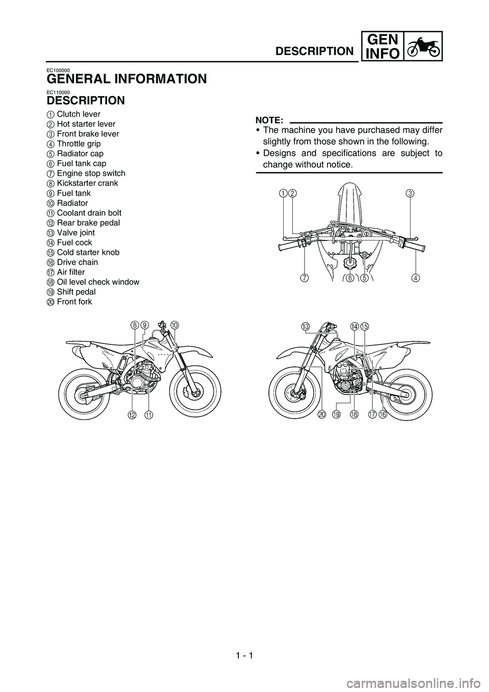
GENERAL INFORMATION
EC110000
DESCRIPTION
1Clutch lever
2Hot starter lever
3Front brake lever
4Throttle grip
5Radiator cap
6Fuel tank cap
7Engine stop switch
8Kickstarter crank
9Fuel tank
0Radiator
ACoolant drain bolt
BRear brake pedal
CValve joint
DFuel cock
ECold starter knob
FDrive chain
GAir filter
HOil level check window
IShift pedal
JFront forkNOTE:
The machine you have purchased may differ
slightly from those shown in the following.
Designs and specifications are subject to
change without notice.
Page 38 of 674
GEN
INFO
1 - 7
SPECIAL TOOLS
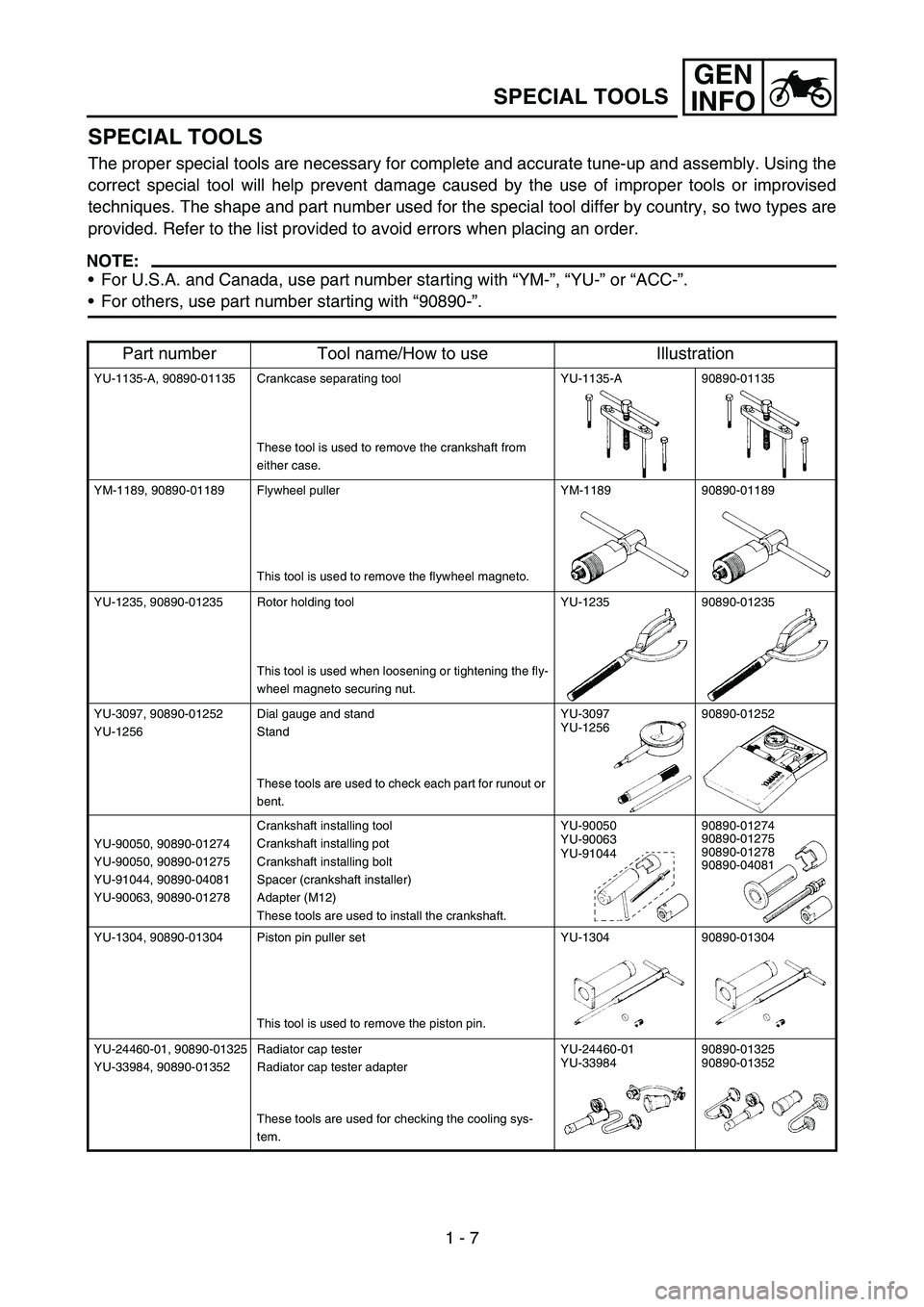
SPECIAL TOOLS
The proper special tools are necessary for complete and accurate tune-up and assembly. Using the
correct special tool will help prevent damage caused by the use of improper tools or improvised
techniques. The shape and part number used for the special tool differ by country, so two types are
provided. Refer to the list provided to avoid errors when placing an order.
NOTE:
For U.S.A. and Canada, use part number starting with “YM-”, “YU-” or “ACC-”.
For others, use part number starting with “90890-”.
Part number Tool name/How to use Illustration
YU-1135-A, 90890-01135 Crankcase separating tool
These tool is used to remove the crankshaft from
either case.YU-1135-A 90890-01135
YM-1189, 90890-01189 Flywheel puller
This tool is used to remove the flywheel magneto.YM-1189 90890-01189
YU-1235, 90890-01235 Rotor holding tool
This tool is used when loosening or tightening the fly-
wheel magneto securing nut.YU-1235 90890-01235
YU-3097, 90890-01252
YU-1256Dial gauge and stand
Stand
These tools are used to check each part for runout or
bent.YU-3097
YU-125690890-01252
YU-90050, 90890-01274
YU-90050, 90890-01275
YU-91044, 90890-04081
YU-90063, 90890-01278Crankshaft installing tool
Crankshaft installing pot
Crankshaft installing bolt
Spacer (crankshaft installer)
Adapter (M12)
These tools are used to install the crankshaft.YU-90050
YU-90063
YU-9104490890-01274
90890-01275
90890-01278
90890-04081
YU-1304, 90890-01304 Piston pin puller set
This tool is used to remove the piston pin.YU-1304 90890-01304
YU-24460-01, 90890-01325
YU-33984, 90890-01352Radiator cap tester
Radiator cap tester adapter
These tools are used for checking the cooling sys-
tem.YU-24460-01
YU-3398490890-01325
90890-01352
Page 82 of 674
SPEC
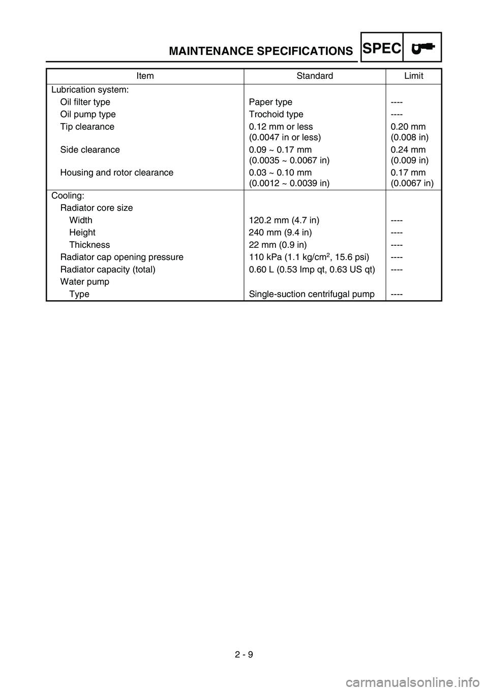
2 - 9 Lubrication system:
Oil filter type Paper type ----
Oil pump type Trochoid type ----
Tip clearance 0.12 mm or less
(0.0047 in or less)0.20 mm
(0.008 in)
Side clearance 0.09 ~ 0.17 mm
(0.0035 ~ 0.0067 in)0.24 mm
(0.009 in)
Housing and rotor clearance 0.03 ~ 0.10 mm
(0.0012 ~ 0.0039 in)0.17 mm
(0.0067 in)
Cooling:
Radiator core size
Width 120.2 mm (4.7 in) ----
Height 240 mm (9.4 in) ----
Thickness 22 mm (0.9 in) ----
Radiator cap opening pressure 110 kPa (1.1 kg/cm
2, 15.6 psi) ----
Radiator capacity (total) 0.60 L (0.53 Imp qt, 0.63 US qt) ----
Water pump
Type Single-suction centrifugal pump ----Item Standard Limit
MAINTENANCE SPECIFICATIONS
Page 83 of 674
SPEC
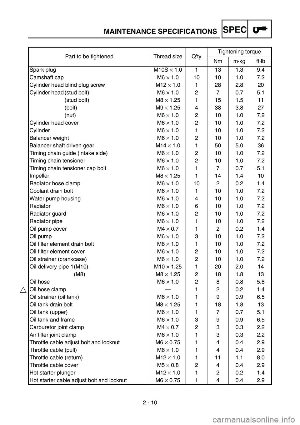
2 - 10 Part to be tightened Thread size Q’tyTightening torque
Nm m·kg ft·lb
Spark plug M10S × 1.0 1 13 1.3 9.4
Camshaft cap M6 × 1.0 10 10 1.0 7.2
Cylinder head blind plug screw M12 × 1.0 1 28 2.8 20
Cylinder head (stud bolt) M6 × 1.0 2 7 0.7 5.1
(stud bolt) M8 × 1.25 1 15 1.5 11
(bolt) M9 × 1.25 4 38 3.8 27
(nut) M6 × 1.0 2 10 1.0 7.2
Cylinder head cover M6 × 1.0 2 10 1.0 7.2
Cylinder M6 × 1.0 1 10 1.0 7.2
Balancer weight M6 × 1.0 2 10 1.0 7.2
Balancer shaft driven gear M14 × 1.0 1 50 5.0 36
Timing chain guide (intake side) M6 × 1.0 2 10 1.0 7.2
Timing chain tensioner M6 × 1.0 2 10 1.0 7.2
Timing chain tensioner cap bolt M6 × 1.0 1 7 0.7 5.1
Impeller M8 × 1.25 1 14 1.4 10
Radiator hose clamp M6 × 1.0 10 2 0.2 1.4
Coolant drain bolt M6 × 1.0 1 10 1.0 7.2
Water pump housing M6 × 1.0 4 10 1.0 7.2
Radiator M6 × 1.0 6 10 1.0 7.2
Radiator guard M6 × 1.0 2 10 1.0 7.2
Radiator pipe M6 × 1.0 1 10 1.0 7.2
Oil pump cover M4 × 0.7 1 2 0.2 1.4
Oil pump M6 × 1.0 3 10 1.0 7.2
Oil filter element drain bolt M6 × 1.0 1 10 1.0 7.2
Oil filter element cover M6 × 1.0 2 10 1.0 7.2
Oil strainer (crankcase) M6 × 1.0 2 10 1.0 7.2
Oil delivery pipe 1 (M10) M10 × 1.25 1 20 2.0 14
(M8) M8 × 1.25 2 18 1.8 13
Oil hose M6 × 1.0 2 8 0.8 5.8
Oil hose clamp—120.21.4
Oil strainer (oil tank) M6 × 1.0 1 9 0.9 6.5
Oil tank drain bolt M8 × 1.25 1 18 1.8 13
Oil tank (upper) M6 × 1.0 1 7 0.7 5.1
Oil tank and frame M6 × 1.0 3 9 0.9 6.5
Carburetor joint clamp M4 × 0.7 2 3 0.3 2.2
Air filter joint clamp M6 × 1.0 1 3 0.3 2.2
Throttle cable adjust bolt and locknut M6 × 0.75 1 4 0.4 2.9
Throttle cable (pull) M6 × 1.0 1 4 0.4 2.9
Throttle cable (return) M12 × 1.0 1 11 1.1 8.0
Throttle cable cover M5 × 0.8 2 4 0.4 2.9
Hot starter plunger M12 × 1.0 1 2 0.2 1.4
Hot starter cable adjust bolt and locknut M6 × 0.75 1 4 0.4 2.9
MAINTENANCE SPECIFICATIONS
Page 133 of 674
SPEC
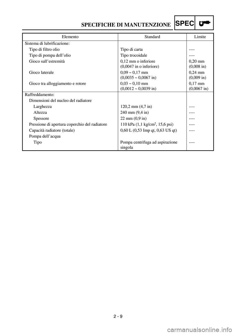
2 - 9 Sistema di lubrificazione:
Tipo di filtro olio Tipo di carta ----
Tipo di pompa dell’olio Tipo trocoidale ----
Gioco sull’estremità0,12 mm o inferiore
(0,0047 in o inferiore)0,20 mm
(0,008 in)
Gioco laterale 0,09 ~ 0,17 mm
(0,0035 ~ 0,0067 in)0,24 mm
(0,009 in)
Gioco tra alloggiamento e rotore 0,03 ~ 0,10 mm
(0,0012 ~ 0,0039 in)0,17 mm
(0,0067 in)
Raffreddamento:
Dimensioni del nucleo del radiatore
Larghezza 120,2 mm (4,7 in) ----
Altezza 240 mm (9,4 in) ----
Spessore 22 mm (0,9 in) ----
Pressione di apertura coperchio del radiatore 110 kPa (1,1 kg/cm
2, 15,6 psi) ----
Capacità radiatore (totale) 0,60 L (0,53 Imp qt, 0,63 US qt) ----
Pompa dell’acqua
Tipo Pompa centrifuga ad aspirazione
singola---- Elemento Standard Limite
SPECIFICHE DI MANUTENZIONE
Page 134 of 674
SPEC
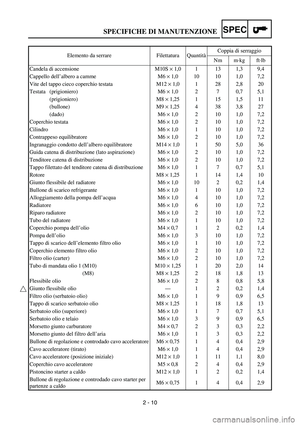
2 - 10 Elemento da serrare Filettatura QuantitàCoppia di serraggio
Nm m·kg ft·lb
Candela di accensione M10S × 1,0 1 13 1,3 9,4
Cappello dell’albero a camme M6 × 1,0 10 10 1,0 7,2
Vite del tappo cieco coperchio testata M12 × 1,0 1 28 2,8 20
Testata (prigioniero) M6 × 1,0 2 7 0,7 5,1
(prigioniero) M8 × 1,25 1 15 1,5 11
(bullone) M9 × 1,25 4 38 3,8 27
(dado) M6 × 1,0 2 10 1,0 7,2
Coperchio testata M6 × 1,0 2 10 1,0 7,2
Cilindro M6 × 1,0 1 10 1,0 7,2
Contrappeso equilibratore M6 × 1,0 2 10 1,0 7,2
Ingranaggio condotto dell’albero equilibratore M14 × 1,0 1 50 5,0 36
Guida catena di distribuzione (lato aspirazione) M6 × 1,0 2 10 1,0 7,2
Tenditore catena di distribuzione M6 × 1,0 2 10 1,0 7,2
Tappo filettato del tenditore catena di distribuzione M6 × 1,0 1 7 0,7 5,1
Rotore M8 × 1,25 1 14 1,4 10
Giunto flessibile del radiatore M6 × 1,0 10 2 0,2 1,4
Bullone di scarico refrigerante M6 × 1,0 1 10 1,0 7,2
Alloggiamento della pompa dell’acqua M6 × 1,0 4 10 1,0 7,2
Radiatore M6 × 1,0 6 10 1,0 7,2
Riparo radiatore M6 × 1,0 2 10 1,0 7,2
Tubo del radiatore M6 × 1,0 1 10 1,0 7,2
Coperchio pompa dell’olio M4 × 0,7 1 2 0,2 1,4
Pompa dell’olio M6 × 1,0 3 10 1,0 7,2
Tappo di scarico dell’elemento filtro olio M6 × 1,0 1 10 1,0 7,2
Coperchio elemento filtro olio M6 × 1,0 2 10 1,0 7,2
Filtro olio (carter) M6 × 1,0 2 10 1,0 7,2
Tubo di mandata olio 1 (M10) M10 × 1,25 1 20 2,0 14
(M8) M8 × 1,25 2 18 1,8 13
Flessibile olio M6 × 1,0 2 8 0,8 5,8
Giunto flessibile olio—120,21,4
Filtro olio (serbatoio olio) M6 × 1,0 1 9 0,9 6,5
Tappo di scarico serbatoio olio M8 × 1,25 1 18 1,8 13
Serbatoio olio (superiore) M6 × 1,0 1 7 0,7 5,1
Serbatoio olio e telaio M6 × 1,0 3 9 0,9 6,5
Morsetto giunto carburatore M4 × 0,7 2 3 0,3 2,2
Morsetto giunto del filtro dell’aria M6 × 1,0 1 3 0,3 2,2
Bullone di regolazione e controdado cavo acceleratore M6 × 0,75 1 4 0,4 2,9
Cavo acceleratore (tirato) M6 × 1,0 1 4 0,4 2,9
Cavo acceleratore (posizione iniziale) M12 × 1,0 1 11 1,1 8,0
Coperchio cavo acceleratore M5 × 0,8 2 4 0,4 2,9
Pistoncino starter a caldo M12 × 1,0 1 2 0,2 1,4
Bullone di regolazione e controdado cavo starter per
partenze a caldoM6 × 0,75 1 4 0,4 2,9
SPECIFICHE DI MANUTENZIONE
Page 143 of 674

2 - 18
SPEC
KABELFÜHRUNGSDIA-
GRAMME
1Kraftstofftank-Belüftungsschlauch
2Kühlerschlauch 1
3Zylinderkopf-Entlüftungsschlauch
4Kühlerschlauch 4
5Kupplungszug
6Drosselklappensensor-Kabel
7Kraftstoffschlauch
8Warmstartzug
9Vergaser-Entlüftungsschlauch
0Vergaser-Überlaufschlauch
AAnschlussabdeckung
ÈDas Ende des Kraftstofftank-Belüf-
tungsschlauchs durch die Bohrung in
der Lenkachse stecken.
ÉDen Zylinderkopf-Entlüftungsschlauch
zur Außenseite des Kühlerschlauchs
1 und zur Innenseite des Kühlerrohrs
(Kühlerschlauch 4) führen.
ÊDen Kupplungszug durch die Führung
leiten.
ËDen Kupplungszug vor die Kühler-
Montagenabe führen.
ÌDen Kraftstoffschlauch zwischen den
Warmstartzug und das Drosselklap-
pensensorkabel verlegen.
ÍDie Vergaser-Entlüftungsschläuche
und den Überlaufschlauch so führen,
dass sie nicht das Federbein berüh-
ren.
ÎDie Anschlussabdeckung so montie-
ren, dass sie nicht zwischen dem
Kühlerschlauch 1 und dem Kühler
sitzt.
DIAGRAMME
D’ACHEMINEMENT DES
CABLES
1Durit de mise à l’air du réservoir de car-
burant
2Durit de radiateur 1
3Durit de mise à l’air de la culasse
4Durit de radiateur 4
5Câble d’embrayage
6Fil du capteur de position de papillon des
gaz
7Durit de carburant
8Câble de starter à chaud
9Durit de mise à l’air du carburateur
0Durit de trop-plein du carburateur
ACache du connecteur
ÈInsérer l’extrémité de la durit de mise à
l’air du réservoir de carburant dans le trou
de la colonne de direction.
ÉAcheminer la durit de mise à l’air de la
culasse à l’extérieur de la durit de radia-
teur 1 et à l’intérieur du tuyau de radiateur
(durit de radiateur 4).
ÊAcheminer le câble d’embrayage dans les
guide-câbles.
ËAcheminer le câble d’embrayage devant
la noix de montage du radiateur.
ÌAcheminer la durit de carburant entre le
câble de starter à chaud et le fil du capteur
de position de papillon des gaz.
ÍAcheminer les durits de mise à l’air du
carburateur et la durit de trop-plein de
manière à ce qu’aucune d’elles n’entre en
contact avec l’amortisseur arrière.
ÎMonter le cache du connecteur de
manière qu’il ne s’intercale pas entre la
durit de radiateur 1 et le radiateur.
SCHEMA PERCORSO DEI
CAVI
1Flessibile di sfiato del serbatoio carbu-
rante
2Flessibile radiatore 1
3Flessibile di sfiato testata
4Flessibile radiatore 4
5Cavo frizione
6Cavo sensore posizione farfalla
7Flessibile del carburante
8Cavo starter per partenze a caldo
9Flessibile di sfiato carburatore
0Flessibile di traboccamento carburatore
ACopertura connettore
ÈInserire l’estremità del flessibile di sfiato
del serbatoio carburante nel foro del rive-
stimento del fusto dello sterzo.
ÉFar passare il flessibile di sfiato della
testata all’esterno del flessibile radiatore 1
e all’interno del tubo del radiatore (flessi-
bile radiatore 4).
ÊFar passare il cavo della frizione attra-
verso le guide cavi.
ËFar passare il cavo della frizione davanti
alla sporgenza di montaggio del radiatore.
ÌFar passare il flessibile del carburante fra
il cavo starter per partenze a caldo e il
cavo sensore posizione farfalla.
ÍFar passare i flessibili di sfiato carbura-
tore e il flessibile di traboccamento carbu-
ratore in modo tale che gli stessi flessibili
non entrino in contatto con l’ammortizza-
tore posteriore.
ÎInstallare la copertura connettore in modo
che non si trovi tra il flessibile radiatore 1
ed il radiatore.
DIAGRAMME D’ACHEMINEMENT DES CABLES
KABELFÜHRUNGSDIAGRAMME
SCHEMA PERCORSO DEI CAVI
Page 145 of 674

2 - 19
SPEC
1Warmstartzug
2Kühlerschlauch 2
3Klemme
4Zündspulenkabel
5Drosselklappensensor-Kabel
6Buckel (Rahmen)
7Ölschlauch
8Schlauchführung
9Leerlaufschalter-Kabel
0CDI-Schwunglichtmagnetzünder-
Kabel
AKupplungszug
BKühler-Entlüftungsschlauch
CMotorstoppschalter-Kabel
DNebenkabelbaum
EZündbox-Halterung
FZündbox
GGaszug
HZylinderkopf-Entlüftungsschlauch
ÈDen Warmstartzug, die Gaszüge, das
Drosselklappensensorkabel und
Zündspulenkabel befestigen.
ÉDas Drosselklappensensorkabel hin-
ter dem Buckel am Rahmen befesti-
gen.
ÊDas Leerlaufschalterkabel am
Ölschlauch befestigen.
ËDas Leerlaufschalterkabel an der
Innenseite des Ölschlauchs entlang
führen.
ÌDas Leerlaufschalterkabel, das CDI-
Schwunglichtmagnetzünder-Kabel
und den Kühler-Entlüftungsschlauch
befestigen.
ÍDas Leerlaufschalterkabel, das CDI-
Schwunglichtmagnetzünder-Kabel,
den Kühler-Entlüftungsschlauch und
den Kupplungszug über der Kühler-
Montagenabe befestigen. 1Câble de starter à chaud
2Durit de radiateur 2
3Collier à pince
4Fil de la bobine d’allumage
5Fil du capteur de position de papillon des
gaz
6Bosse (cadre)
7Durit d’huile
8Guide de durit
9Fil du contacteur de point mort
0Fil du volant magnétique C.D.I.
ACâble d’embrayage
BDurit de mise à l’air du radiateur
CFil du coupe-circuit du moteur
DFaisceau de fils secondaire
ESupport de boîtier CDI
FBoîtier C.D.I.
GCâble des gaz
HDurit de mise à l’air de la culasse
ÈAttacher ensemble le câble de starter à
chaud, les câbles des gaz, le fil du capteur
de position de papillon des gaz et le fil de
la bobine d’allumage.
ÉAttacher le fil du capteur de position de
papillon des gaz derrière la bosse du
cadre.
ÊAttacher le fil du contacteur de point mort
à la durit d’huile.
ËAcheminer le fil du contacteur de point
mort vers l’intérieur de la durit d’huile.
ÌAttacher ensemble le fil du contacteur de
point mort, le fil du volant magnétique
CDI et la durit de mise à l’air du radiateur.
ÍAttacher le fil du contacteur de point
mort, le fil du volant magnétique CDI, la
durit de mise à l’air du radiateur et le
câble d’embrayage à la noix de montage
du radiateur.1Cavo starter per partenze a caldo
2Flessibile radiatore 2
3Morsetto
4Cavo bobina di accensione
5Cavo sensore posizione farfalla
6Gobba (telaio)
7Flessibile olio
8Guida flessibile
9Cavo interruttore folle
0Cavo magnete CDI
ACavo frizione
BFlessibile di sfiato radiatore
CCavo interruttore di arresto motore
DCablaggio secondario
EStaffa unità CDI
FUnità CDI
GCavo acceleratore
HFlessibile di sfiato testata
ÈFissare il cavo starter per partenze a
caldo, i cavi dell’acceleratore, il cavo sen-
sore posizione farfalla e il cavo bobina di
accensione.
ÉFissare il cavo sensore posizione farfalla
dietro la gobba del telaio.
ÊFissare il cavo dell’interruttore folle al
flessibile olio.
ËFar passare il cavo dell’interruttore folle
all’interno del flessibile olio.
ÌFissare il cavo dell’interruttore folle, il
cavo magnete CDI e il flessibile di sfiato
radiatore.
ÍFissare il cavo dell’interruttore folle, il
cavo magnete CDI, il flessibile di sfiato
radiatore e il cavo frizione oltre la spor-
genza di montaggio del radiatore.
DIAGRAMME D’ACHEMINEMENT DES CABLES
KABELFÜHRUNGSDIAGRAMME
SCHEMA PERCORSO DEI CAVI
Page 155 of 674
3 - 2
INSP
ADJ
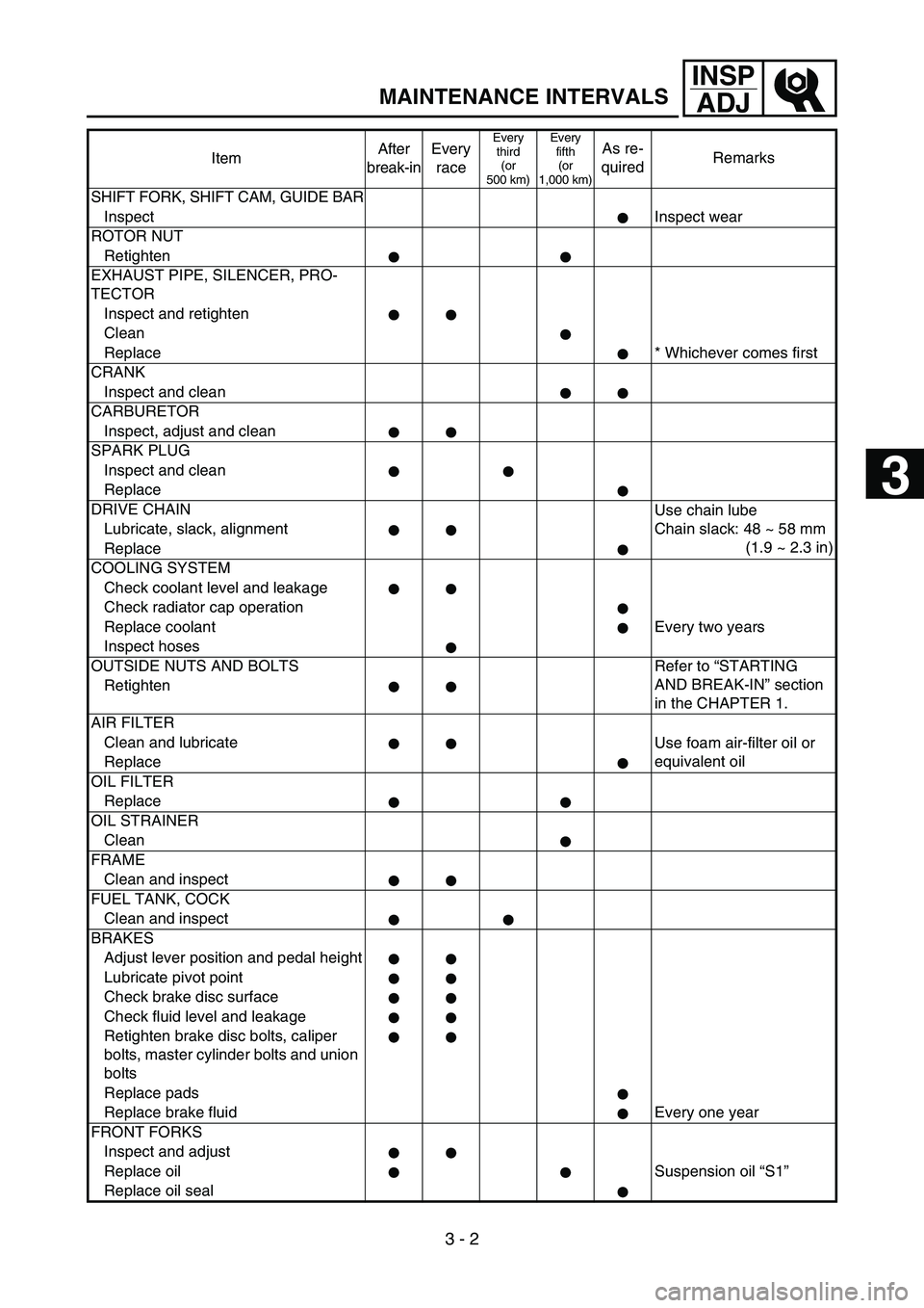
MAINTENANCE INTERVALS
SHIFT FORK, SHIFT CAM, GUIDE BAR
InspectInspect wear
ROTOR NUT
Retighten
EXHAUST PIPE, SILENCER, PRO-
TECTOR
Inspect and retighten
Clean
Replace * Whichever comes first
CRANK
Inspect and clean
CARBURETOR
Inspect, adjust and clean
SPARK PLUG
Inspect and clean
Replace
DRIVE CHAIN
Use chain lube
Chain slack: 48 ~ 58 mm
(1.9 ~ 2.3 in) Lubricate, slack, alignment
Replace
COOLING SYSTEM
Check coolant level and leakage
Check radiator cap operation
Replace coolant Every two years
Inspect hoses
OUTSIDE NUTS AND BOLTS Refer to “STARTING
AND BREAK-IN” section
in the CHAPTER 1. Retighten
AIR FILTER
Clean and lubricate
Use foam air-filter oil or
equivalent oil
Replace
OIL FILTER
Replace
OIL STRAINER
Clean
FRAME
Clean and inspect
FUEL TANK, COCK
Clean and inspect
BRAKES
Adjust lever position and pedal height
Lubricate pivot point
Check brake disc surface
Check fluid level and leakage
Retighten brake disc bolts, caliper
bolts, master cylinder bolts and union
bolts
Replace pads
Replace brake fluid Every one year
FRONT FORKS
Inspect and adjust
Replace oil Suspension oil “S1”
Replace oil sealItemAfter
break-inEvery
race
Every
third
(or
500 km)Every
fifth
(or
1,000 km)As re-
quiredRemarks
3