Clutch assembly YAMAHA YZ250F 2007 Owners Manual
[x] Cancel search | Manufacturer: YAMAHA, Model Year: 2007, Model line: YZ250F, Model: YAMAHA YZ250F 2007Pages: 676, PDF Size: 21.24 MB
Page 39 of 676
GEN
INFO
1 - 8
SPECIAL TOOLS
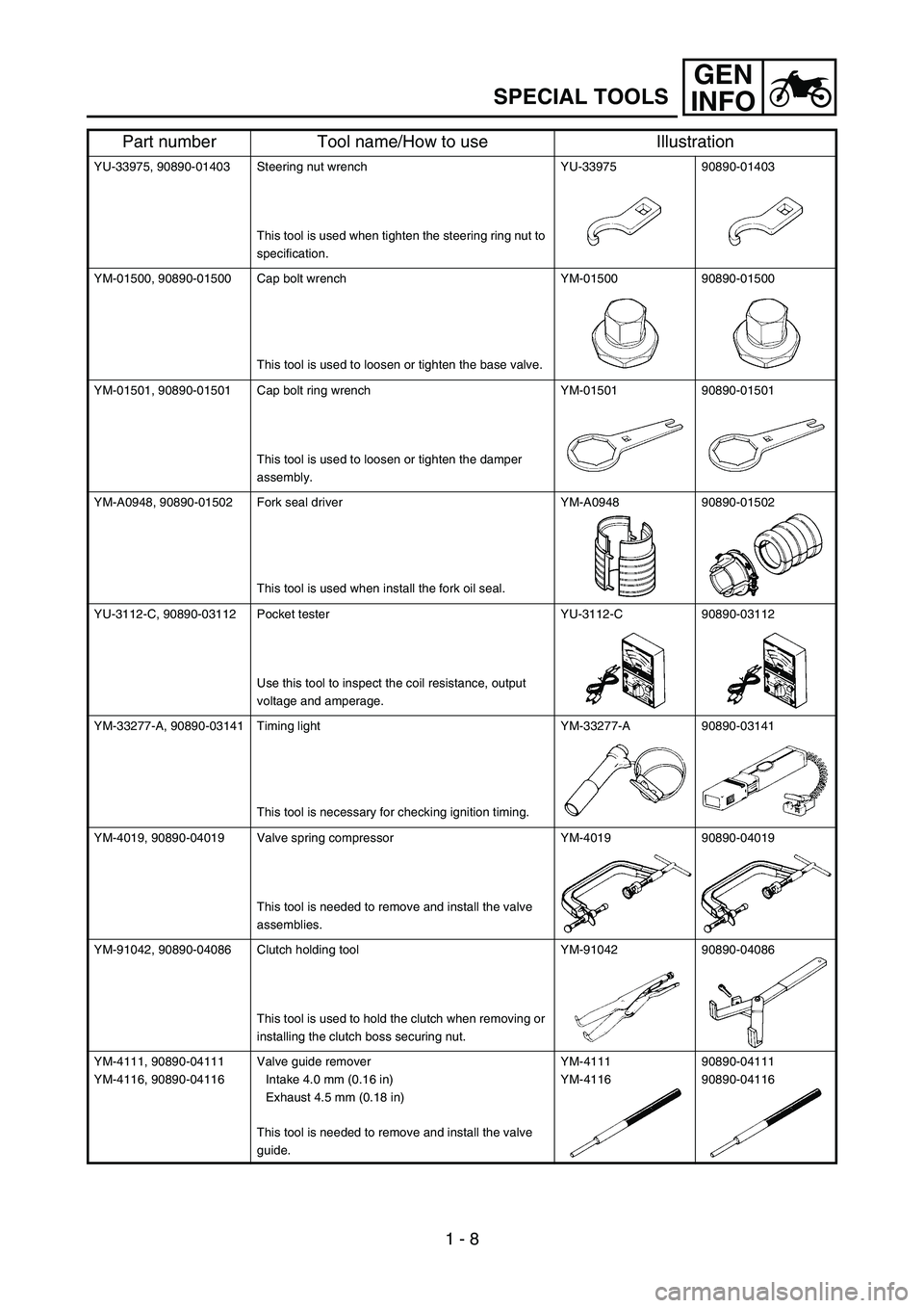
YU-33975, 90890-01403 Steering nut wrench
This tool is used when tighten the steering ring nut to
specification.YU-33975 90890-01403
YM-01500, 90890-01500 Cap bolt wrench
This tool is used to loosen or tighten the base valve.YM-01500 90890-01500
YM-01501, 90890-01501 Cap bolt ring wrench
This tool is used to loosen or tighten the damper
assembly.YM-01501 90890-01501
YM-A0948, 90890-01502 Fork seal driver
This tool is used when install the fork oil seal.YM-A0948 90890-01502
YU-3112-C, 90890-03112 Pocket tester
Use this tool to inspect the coil resistance, output
voltage and amperage.YU-3112-C 90890-03112
YM-33277-A, 90890-03141 Timing light
This tool is necessary for checking ignition timing.YM-33277-A 90890-03141
YM-4019, 90890-04019 Valve spring compressor
This tool is needed to remove and install the valve
assemblies.YM-4019 90890-04019
YM-91042, 90890-04086 Clutch holding tool
This tool is used to hold the clutch when removing or
installing the clutch boss securing nut.YM-91042 90890-04086
YM-4111, 90890-04111
YM-4116, 90890-04116Valve guide remover
Intake 4.0 mm (0.16 in)
Exhaust 4.5 mm (0.18 in)
This tool is needed to remove and install the valve
guide.YM-4111
YM-411690890-04111
90890-04116
Part number Tool name/How to use Illustration
Page 87 of 676
SPEC
2 - 14
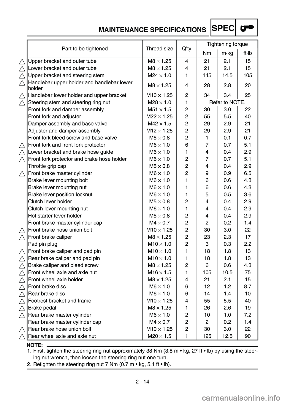
NOTE:
1. First, tighten the steering ring nut approximately 38 Nm (3.8 m kg, 27 ft lb) by using the steer-
ing nut wrench, then loosen the steering ring nut one turn.
2. Retighten the steering ring nut 7 Nm (0.7 m kg, 5.1 ft lb). Part to be tightened Thread size Q’tyTightening torque
Nm m·kg ft·lb
Upper bracket and outer tube M8 × 1.25 4 21 2.1 15
Lower bracket and outer tube M8 × 1.25 4 21 2.1 15
Upper bracket and steering stem M24 × 1.0 1 145 14.5 105
Handlebar upper holder and handlebar lower
holderM8 × 1.25 4 28 2.8 20
Handlebar lower holder and upper bracket M10 × 1.25 2 34 3.4 25
Steering stem and steering ring nut M28 × 1.0 1 Refer to NOTE.
Front fork and damper assembly M51 × 1.5 2 30 3.0 22
Front fork and adjuster M22 × 1.25 2 55 5.5 40
Damper assembly and base valve M42 × 1.5 2 29 2.9 21
Adjuster and damper assembly M12 × 1.25 2 29 2.9 21
Front fork bleed screw and base valve M5 × 0.8 2 1 0.1 0.7
Front fork and front fork protector M6 × 1.0 6 7 0.7 5.1
Lower bracket and brake hose guide M6 × 1.0 1 4 0.4 2.9
Front fork protector and brake hose holder M6 × 1.0 2 7 0.7 5.1
Throttle grip cap M5 × 0.8 2 4 0.4 2.9
Front brake master cylinder M6 × 1.0 2 9 0.9 6.5
Brake lever mounting bolt M6 × 1.0 1 6 0.6 4.3
Brake lever mounting nut M6 × 1.0 1 6 0.6 4.3
Brake lever position locknut M6 × 1.0 1 5 0.5 3.6
Clutch lever holder M5 × 0.8 2 4 0.4 2.9
Clutch lever mounting nut M6 × 1.0 1 4 0.4 2.9
Hot starter lever holder M5 × 0.8 2 4 0.4 2.9
Front brake master cylinder cap M4 × 0.7 2 2 0.2 1.4
Front brake hose union bolt M10 × 1.25 2 30 3.0 22
Front brake caliper M8 × 1.25 2 23 2.3 17
Pad pin plug M10 × 1.0 2 3 0.3 2.2
Front brake caliper and pad pin M10 × 1.0 1 18 1.8 13
Rear brake caliper and pad pin M10 × 1.0 1 18 1.8 13
Brake caliper and bleed screw M8 × 1.25 2 6 0.6 4.3
Front wheel axle and axle nut M16 × 1.5 1 105 10.5 75
Front wheel axle holder M8 × 1.25 4 21 2.1 15
Front brake disc M6 × 1.0 6 12 1.2 8.7
Rear brake disc M6 × 1.0 6 14 1.4 10
Footrest bracket and frame M10 × 1.25 4 55 5.5 40
Brake pedal M8 × 1.25 1 26 2.6 19
Rear brake master cylinder M6 × 1.0 2 10 1.0 7.2
Rear brake master cylinder cap M4 × 0.7 2 2 0.2 1.4
Rear brake hose union bolt M10 × 1.25 2 30 3.0 22
Rear wheel axle and axle nut M20 × 1.5 1 125 12.5 90
MAINTENANCE SPECIFICATIONS
Page 264 of 676
4 - 2
ENG
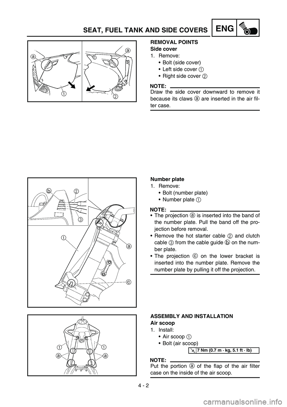
REMOVAL POINTS
Side cover
1. Remove:
Bolt (side cover)
Left side cover 1
Right side cover 2
NOTE:
Draw the side cover downward to remove it
because its claws a are inserted in the air fil-
ter case.
Number plate
1. Remove:
Bolt (number plate)
Number plate 1
NOTE:
The projection a is inserted into the band of
the number plate. Pull the band off the pro-
jection before removal.
Remove the hot starter cable 2 and clutch
cable 3 from the cable guide b on the num-
ber plate.
The projection c on the lower bracket is
inserted into the number plate. Remove the
number plate by pulling it off the projection.
ASSEMBLY AND INSTALLATION
Air scoop
1. Install:
Air scoop 1
Bolt (air scoop)
NOTE:
Put the portion a of the flap of the air filter
case on the inside of the air scoop.
T R..7 Nm (0.7 m · kg, 5.1 ft · lb)
SEAT, FUEL TANK AND SIDE COVERS
Page 360 of 676
4 - 50
ENGCLUTCH
EC4A0000
CLUTCH
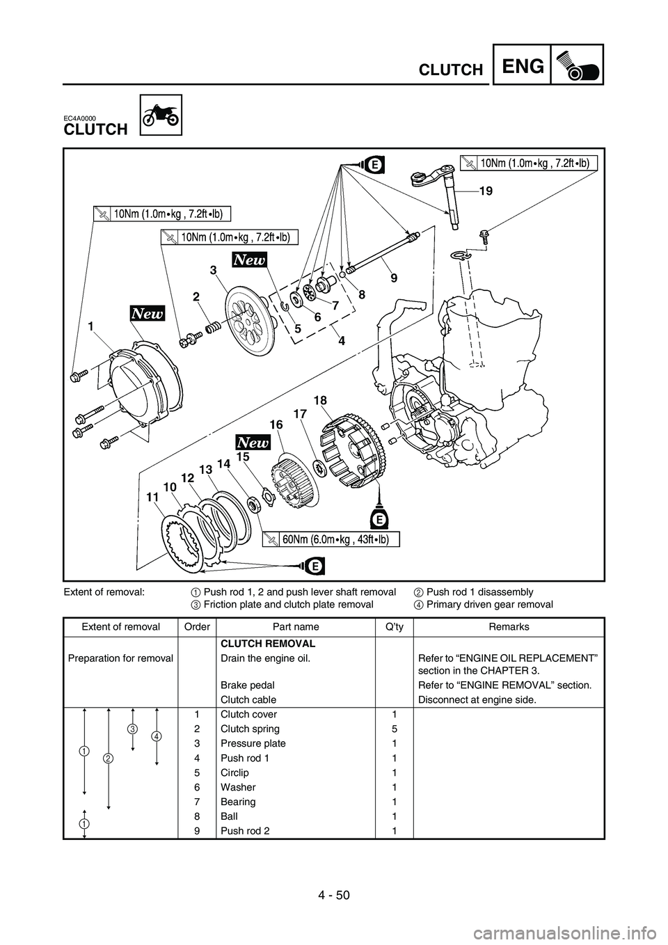
Extent of removal:
1 Push rod 1, 2 and push lever shaft removal
2 Push rod 1 disassembly
3 Friction plate and clutch plate removal
4 Primary driven gear removal
Extent of removal Order Part name Q’ty Remarks
CLUTCH REMOVAL
Preparation for removal Drain the engine oil. Refer to “ENGINE OIL REPLACEMENT”
section in the CHAPTER 3.
Brake pedal Refer to “ENGINE REMOVAL” section.
Clutch cable Disconnect at engine side.
1 Clutch cover 1
2 Clutch spring 5
3 Pressure plate 1
4 Push rod 1 1
5 Circlip 1
6 Washer 1
7 Bearing 1
8Ball 1
9 Push rod 2 1
1
4
1
3
2
Page 368 of 676
4 - 54
ENGCLUTCH
EC4A5000
ASSEMBLY AND INSTALLATION
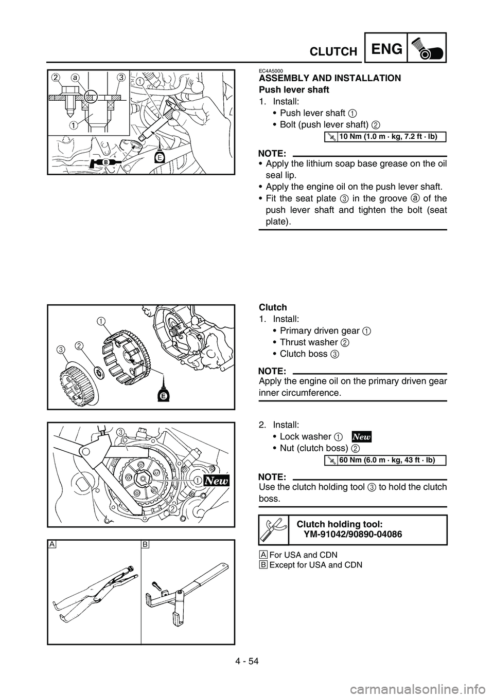
Push lever shaft
1. Install:
Push lever shaft 1
Bolt (push lever shaft) 2
NOTE:
Apply the lithium soap base grease on the oil
seal lip.
Apply the engine oil on the push lever shaft.
Fit the seat plate 3 in the groove a of the
push lever shaft and tighten the bolt (seat
plate).
T R..10 Nm (1.0 m · kg, 7.2 ft · lb)
Clutch
1. Install:
Primary driven gear 1
Thrust washer 2
Clutch boss 3
NOTE:
Apply the engine oil on the primary driven gear
inner circumference.
2. Install:
Lock washer 1
Nut (clutch boss) 2
NOTE:
Use the clutch holding tool 3 to hold the clutch
boss.
È
For USA and CDN
ÉExcept for USA and CDN
Clutch holding tool:
YM-91042/90890-04086
T R..60 Nm (6.0 m · kg, 43 ft · lb)
È
É
Page 394 of 676
4 - 67
ENGOIL PUMP
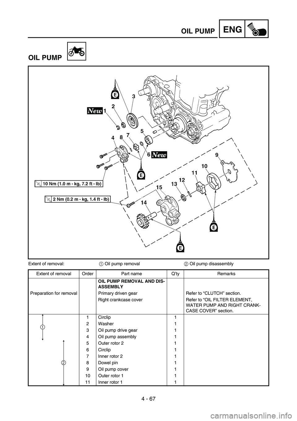
OIL PUMP
Extent of removal:
1 Oil pump removal
2 Oil pump disassembly
Extent of removal Order Part name Q’ty Remarks
OIL PUMP REMOVAL AND DIS-
ASSEMBLY
Preparation for removal Primary driven gear Refer to “CLUTCH” section.
Right crankcase cover Refer to “OIL FILTER ELEMENT,
WATER PUMP AND RIGHT CRANK-
CASE COVER” section.
1 Circlip 1
2 Washer 1
3 Oil pump drive gear 1
4 Oil pump assembly 1
5 Outer rotor 2 1
6 Circlip 1
7 Inner rotor 2 1
8 Dowel pin 1
9 Oil pump cover 1
10 Outer rotor 1 1
11 Inner rotor 1 1
2
1