JET YAMAHA YZ250F 2007 Owners Manual
[x] Cancel search | Manufacturer: YAMAHA, Model Year: 2007, Model line: YZ250F, Model: YAMAHA YZ250F 2007Pages: 676, PDF Size: 21.24 MB
Page 54 of 676
1 - 12
GEN
INFO
CONTROL FUNCTIONS
EC15R001
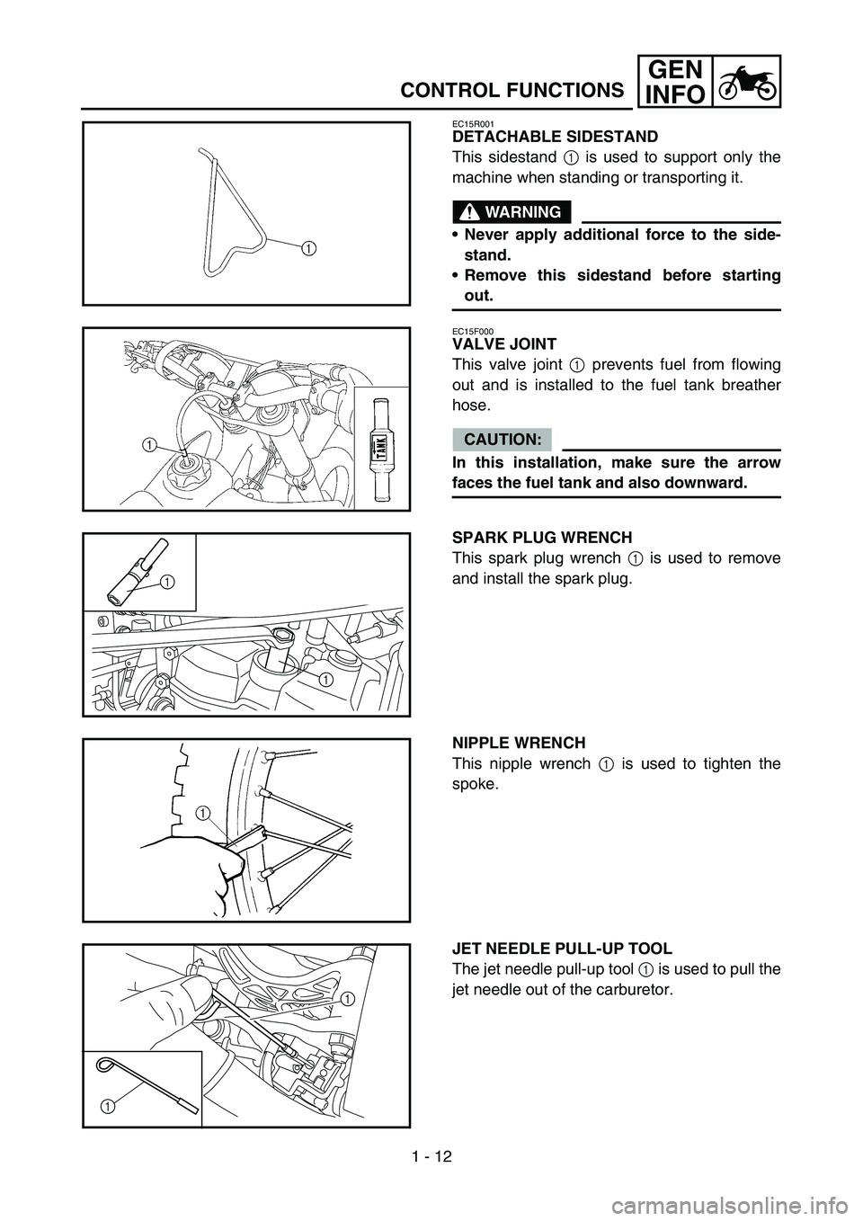
DETACHABLE SIDESTAND
This sidestand 1 is used to support only the
machine when standing or transporting it.
WARNING
Never apply additional force to the side-
stand.
Remove this sidestand before starting
out.
EC15F000
VALVE JOINT
This valve joint 1 prevents fuel from flowing
out and is installed to the fuel tank breather
hose.
CAUTION:
In this installation, make sure the arrow
faces the fuel tank and also downward.
SPARK PLUG WRENCH
This spark plug wrench 1 is used to remove
and install the spark plug.
1
1
NIPPLE WRENCH
This nipple wrench 1 is used to tighten the
spoke.
JET NEEDLE PULL-UP TOOL
The jet needle pull-up tool 1 is used to pull the
jet needle out of the carburetor.
1
1
Page 81 of 676
SPEC
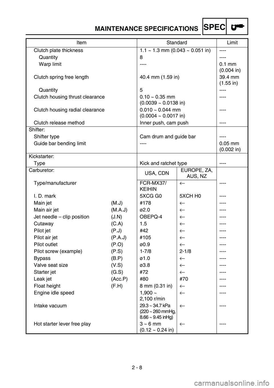
2 - 8 Clutch plate thickness 1.1 ~ 1.3 mm (0.043 ~ 0.051 in) ----
Quantity 8 ----
Warp limit ---- 0.1 mm
(0.004 in)
Clutch spring free length 40.4 mm (1.59 in) 39.4 mm
(1.55 in)
Quantity 5 ----
Clutch housing thrust clearance 0.10 ~ 0.35 mm
(0.0039 ~ 0.0138 in)----
Clutch housing radial clearance 0.010 ~ 0.044 mm
(0.0004 ~ 0.0017 in)----
Clutch release method Inner push, cam push ----
Shifter:
Shifter type Cam drum and guide bar ----
Guide bar bending limit ---- 0.05 mm
(0.002 in)
Kickstarter:
Type Kick and ratchet type ----
Carburetor:
USA, CDNEUROPE, ZA,
AUS, NZ
Type/manufacturer FCR-MX37/
KEIHIN
←----
I. D. mark 5XCG G0 5XCH H0 ----
Main jet (M.J) #178
←----
Main air jet (M.A.J)ø2.0
←----
Jet needle – clip position (J.N) OBEPQ-4
←----
Cutaway (C.A) 1.5
←----
Pilot jet (P.J) #42
←----
Pilot air jet (P.A.J) #105
←----
Pilot outlet (P.O)ø0.9
←----
Pilot screw (example) (P.S) 1-7/8 2-1/8 ----
Bypass (B.P)ø1.0
←----
Valve seat size (V.S)ø3.8
←----
Starter jet (G.S) #72
←----
Leak jet (Acc.P) #80 #70 ----
Float height (F.H) 8 mm (0.31 in)
←----
Engine idle speed 1,900 ~
2,100 r/min
←----
Intake vacuum
29.3 ~ 34.7 kPa
(220 ~ 260 mmHg,
8.66 ~ 9.45 inHg)←----
Hot starter lever free play 3 ~ 6 mm
(0.12 ~ 0.24 in)
←---- Item Standard Limit
MAINTENANCE SPECIFICATIONS
Page 280 of 676
4 - 10
ENGCARBURETOR
EC468000
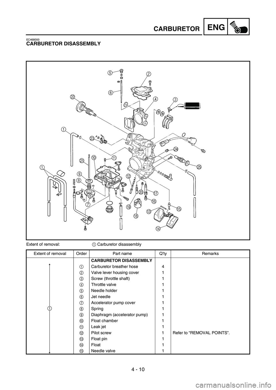
CARBURETOR DISASSEMBLY
Extent of removal:
1 Carburetor disassembly
Extent of removal Order Part name Q’ty Remarks
CARBURETOR DISASSEMBLY
1Carburetor breather hose 4
2Valve lever housing cover 1
3Screw (throttle shaft) 1
4Throttle valve 1
5Needle holder 1
6Jet needle 1
7Accelerator pump cover 1
8Spring 1
9Diaphragm (accelerator pump) 1
0Float chamber 1
ALeak jet 1
BPilot screw 1 Refer to “REMOVAL POINTS”.
CFloat pin 1
DFloat 1
ENeedle valve 1
1
Page 282 of 676
4 - 11
ENGCARBURETOR
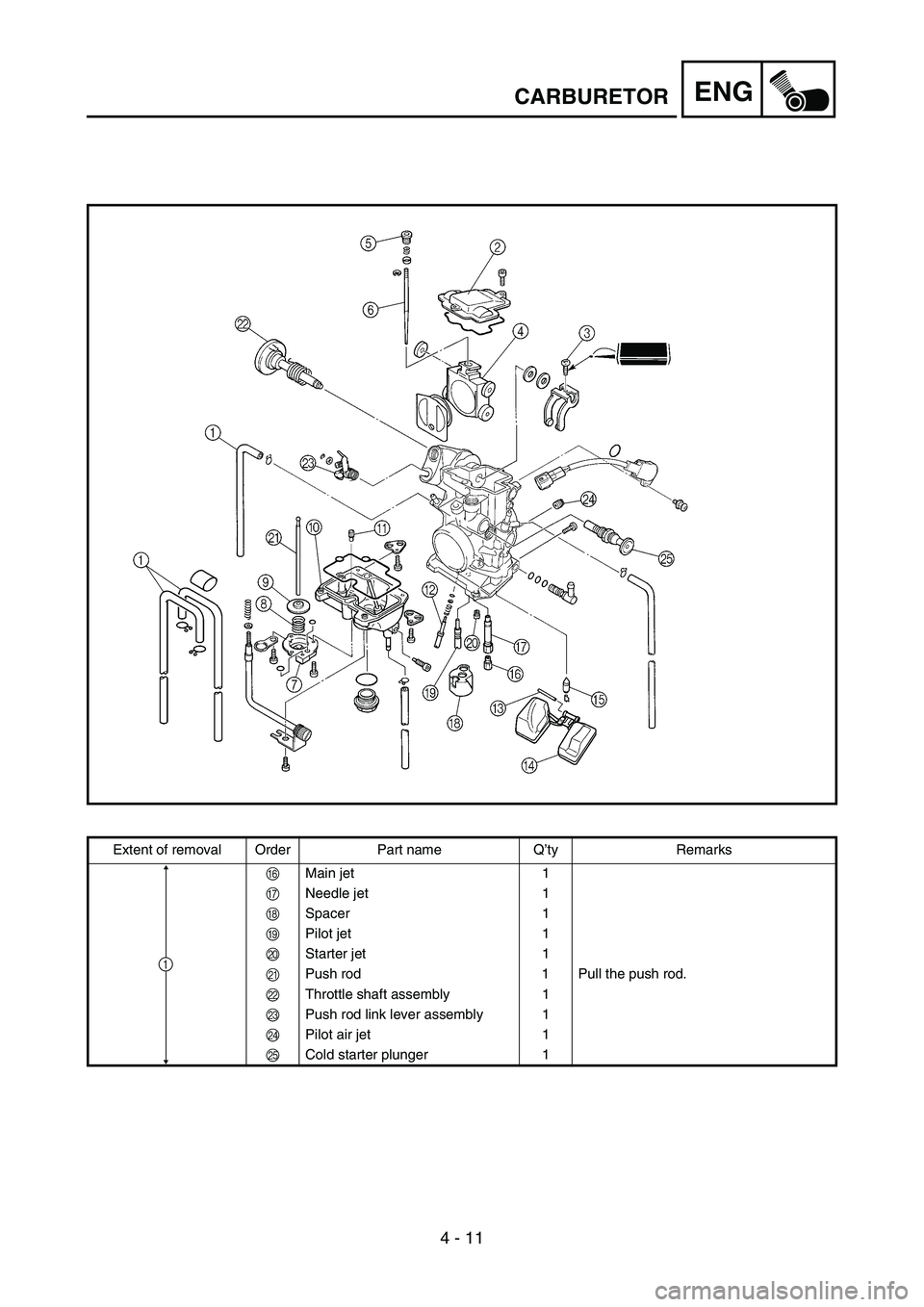
Extent of removal Order Part name Q’ty Remarks
FMain jet 1
GNeedle jet 1
HSpacer 1
IPilot jet 1
JStarter jet 1
KPush rod 1 Pull the push rod.
LThrottle shaft assembly 1
MPush rod link lever assembly 1
NPilot air jet 1
OCold starter plunger 1
1
Page 284 of 676
4 - 12
ENGCARBURETOR
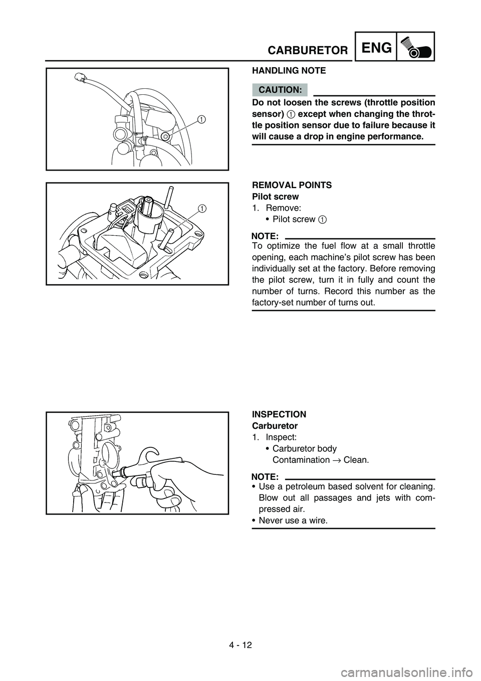
HANDLING NOTE
CAUTION:
Do not loosen the screws (throttle position
sensor)
1 except when changing the throt-
tle position sensor due to failure because it
will cause a drop in engine performance.
1
REMOVAL POINTS
Pilot screw
1. Remove:
Pilot screw 1
NOTE:
To optimize the fuel flow at a small throttle
opening, each machine’s pilot screw has been
individually set at the factory. Before removing
the pilot screw, turn it in fully and count the
number of turns. Record this number as the
factory-set number of turns out.
INSPECTION
Carburetor
1. Inspect:
Carburetor body
Contamination → Clean.
NOTE:
Use a petroleum based solvent for cleaning.
Blow out all passages and jets with com-
pressed air.
Never use a wire.
Page 286 of 676
4 - 13
ENGCARBURETOR
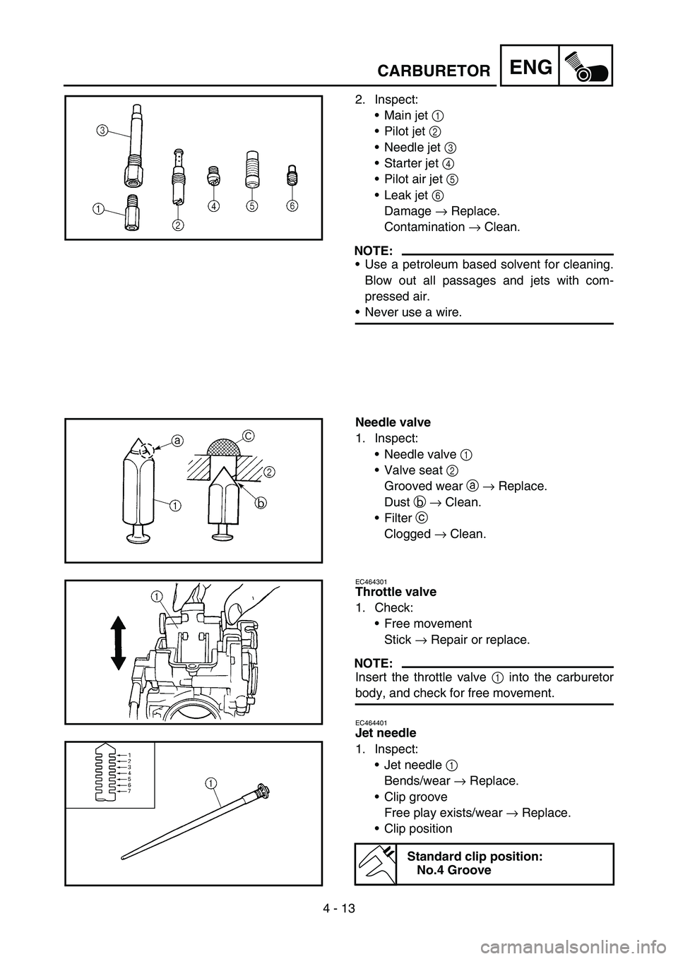
2. Inspect:
Main jet 1
Pilot jet 2
Needle jet 3
Starter jet 4
Pilot air jet 5
Leak jet 6
Damage → Replace.
Contamination → Clean.
NOTE:
Use a petroleum based solvent for cleaning.
Blow out all passages and jets with com-
pressed air.
Never use a wire.
Needle valve
1. Inspect:
Needle valve 1
Valve seat 2
Grooved wear a → Replace.
Dust b → Clean.
Filter c
Clogged → Clean.
EC464301
Throttle valve
1. Check:
Free movement
Stick → Repair or replace.
NOTE:
Insert the throttle valve 1 into the carburetor
body, and check for free movement.
EC464401
Jet needle
1. Inspect:
Jet needle 1
Bends/wear → Replace.
Clip groove
Free play exists/wear → Replace.
Clip position
Standard clip position:
No.4 Groove
Page 290 of 676
4 - 15
ENG
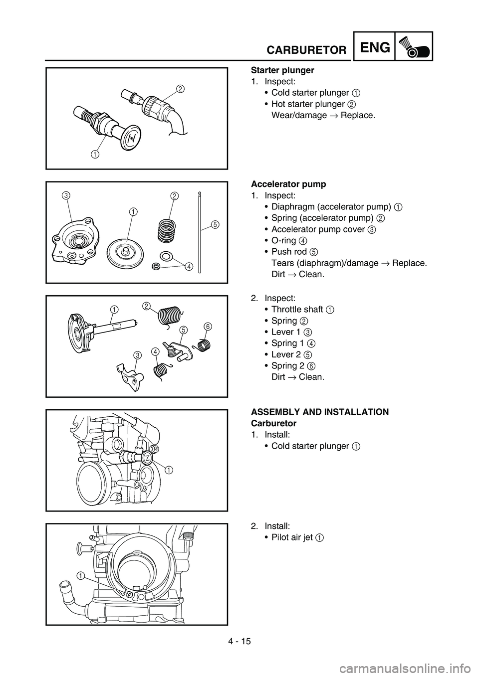
Starter plunger
1. Inspect:
Cold starter plunger 1
Hot starter plunger 2
Wear/damage → Replace.
Accelerator pump
1. Inspect:
Diaphragm (accelerator pump) 1
Spring (accelerator pump) 2
Accelerator pump cover 3
O-ring 4
Push rod 5
Tears (diaphragm)/damage → Replace.
Dirt → Clean.
2. Inspect:
Throttle shaft 1
Spring 2
Lever 1 3
Spring 1 4
Lever 2 5
Spring 2 6
Dirt → Clean.
12
3456
ASSEMBLY AND INSTALLATION
Carburetor
1. Install:
Cold starter plunger 1
2. Install:
Pilot air jet 1
1
CARBURETOR
Page 294 of 676
4 - 17
ENGCARBURETOR
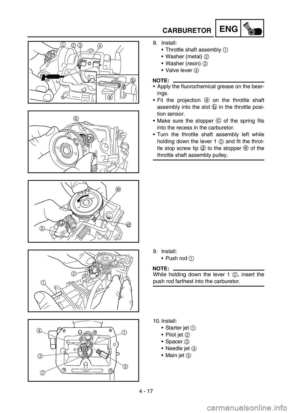
8. Install:
Throttle shaft assembly 1
Washer (metal) 2
Washer (resin) 3
Valve lever 4
NOTE:
Apply the fluorochemical grease on the bear-
ings.
Fit the projection a on the throttle shaft
assembly into the slot b in the throttle posi-
tion sensor.
Make sure the stopper c of the spring fits
into the recess in the carburetor.
Turn the throttle shaft assembly left while
holding down the lever 1 5 and fit the throt-
tle stop screw tip d to the stopper e of the
throttle shaft assembly pulley.
1
23
4
b
a
c
e
d
5
9. Install:
Push rod 1
NOTE:
While holding down the lever 1 2, insert the
push rod farthest into the carburetor.12
10. Install:
Starter jet 1
Pilot jet 2
Spacer 3
Needle jet 4
Main jet 5
Page 296 of 676
4 - 18
ENGCARBURETOR
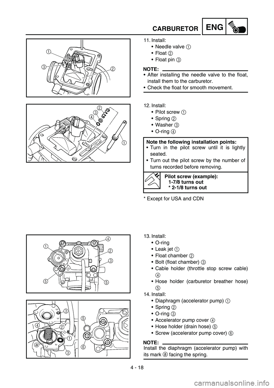
11. Install:
Needle valve 1
Float 2
Float pin 3
NOTE:
After installing the needle valve to the float,
install them to the carburetor.
Check the float for smooth movement.
12. Install:
Pilot screw 1
Spring 2
Washer 3
O-ring 4
* Except for USA and CDNNote the following installation points:
Turn in the pilot screw until it is lightly
seated.
Turn out the pilot screw by the number of
turns recorded before removing.
Pilot screw (example):
1-7/8 turns out
* 2-1/8 turns out
13. Install:
O-ring
Leak jet 1
Float chamber 2
Bolt (float chamber) 3
Cable holder (throttle stop screw cable)
4
Hose holder (carburetor breather hose)
5
14. Install:
Diaphragm (accelerator pump) 1
Spring 2
O-ring 3
Accelerator pump cover 4
Hose holder (drain hose) 5
Screw (accelerator pump cover) 6
NOTE:
Install the diaphragm (accelerator pump) with
its mark a facing the spring.
Page 298 of 676
4 - 19
ENGCARBURETOR
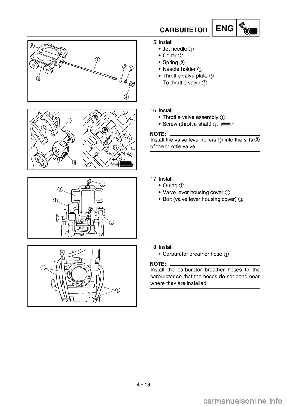
15. Install:
Jet needle 1
Collar 2
Spring 3
Needle holder 4
Throttle valve plate 5
To throttle valve 6.5
6
1
2
3
4
16. Install:
Throttle valve assembly 1
Screw (throttle shaft) 2
NOTE:
Install the valve lever rollers 3 into the slits a
of the throttle valve.
17. Install:
O-ring 1
Valve lever housing cover 2
Bolt (valve lever housing cover) 3
18. Install:
Carburetor breather hose 1
NOTE:
Install the carburetor breather hoses to the
carburetor so that the hoses do not bend near
where they are installed.