engine YAMAHA YZ250F 2012 User Guide
[x] Cancel search | Manufacturer: YAMAHA, Model Year: 2012, Model line: YZ250F, Model: YAMAHA YZ250F 2012Pages: 198, PDF Size: 11.78 MB
Page 25 of 198
1-15
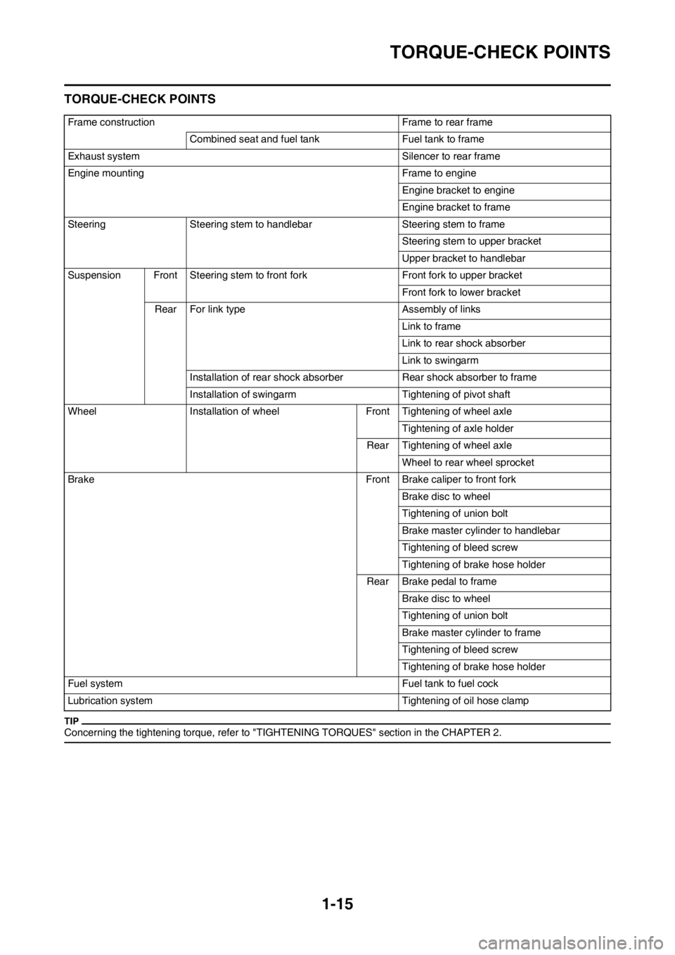
TORQUE-CHECK POINTS
TORQUE-CHECK POINTS
Concerning the tightening torque, refer to "TIGHTENING TORQUES" section in the CHAPTER 2.
Frame construction Frame to rear frame
Combined seat and fuel tank Fuel tank to frame
Exhaust system Silencer to rear frame
Engine mounting Frame to engine
Engine bracket to engine
Engine bracket to frame
Steering Steering stem to handlebar Steering stem to frame
Steering stem to upper bracket
Upper bracket to handlebar
Suspension Front Steering stem to front fork Front fork to upper bracket
Front fork to lower bracket
Rear For link type Assembly of links
Link to frame
Link to rear shock absorber
Link to swingarm
Installation of rear shock absorber Rear shock absorber to frame
Installation of swingarm Tightening of pivot shaft
Wheel Installation of wheel Front Tightening of wheel axle
Tightening of axle holder
Rear Tightening of wheel axle
Wheel to rear wheel sprocket
Brake Front Brake caliper to front fork
Brake disc to wheel
Tightening of union bolt
Brake master cylinder to handlebar
Tightening of bleed screw
Tightening of brake hose holder
Rear Brake pedal to frame
Brake disc to wheel
Tightening of union bolt
Brake master cylinder to frame
Tightening of bleed screw
Tightening of brake hose holder
Fuel system Fuel tank to fuel cock
Lubrication system Tightening of oil hose clamp
Page 26 of 198
1-16
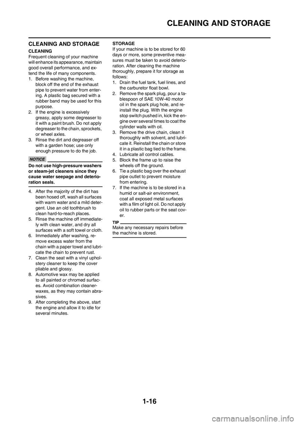
CLEANING AND STORAGE
CLEANING AND STORAGE
CLEANING
Frequent cleaning of your machine
will enhance its appearance, maintain
good overall performance, and ex-
tend the life of many components.
1. Before washing the machine,
block off the end of the exhaust
pipe to prevent water from enter-
ing. A plastic bag secured with a
rubber band may be used for this
purpose.
2. If the engine is excessively
greasy, apply some degreaser to
it with a paint brush. Do not apply
degreaser to the chain, sprockets,
or wheel axles.
3. Rinse the dirt and degreaser off
with a garden hose; use only
enough pressure to do the job.
Do not use high-pressure washers
or steam-jet cleaners since they
cause water seepage and deterio-
ration seals.
4. After the majority of the dirt has
been hosed off, wash all surfaces
with warm water and a mild deter-
gent. Use an old toothbrush to
clean hard-to-reach places.
5. Rinse the machine off immediate-
ly with clean water, and dry all
surfaces with a soft towel or cloth.
6. Immediately after washing, re-
move excess water from the
chain with a paper towel and lubri-
cate the chain to prevent rust.
7. Clean the seat with a vinyl uphol-
stery cleaner to keep the cover
pliable and glossy.
8. Automotive wax may be applied
to all painted or chromed surfac-
es. Avoid combination cleaner-
waxes, as they may contain abra-
sives.
9. After completing the above, start
the engine and allow it to idle for
several minutes.STORAGE
If your machine is to be stored for 60
days or more, some preventive mea-
sures must be taken to avoid deterio-
ration. After cleaning the machine
thoroughly, prepare it for storage as
follows:
1. Drain the fuel tank, fuel lines, and
the carburetor float bowl.
2. Remove the spark plug, pour a ta-
blespoon of SAE 10W-40 motor
oil in the spark plug hole, and re-
install the plug. With the engine
stop switch pushed in, kick the en-
gine over several times to coat the
cylinder walls with oil.
3. Remove the drive chain, clean it
thoroughly with solvent, and lubri-
cate it. Reinstall the chain or store
it in a plastic bag tied to the frame.
4. Lubricate all control cables.
5. Block the frame up to raise the
wheels off the ground.
6. Tie a plastic bag over the exhaust
pipe outlet to prevent moisture
from entering.
7. If the machine is to be stored in a
humid or salt-air environment,
coat all exposed metal surfaces
with a film of light oil. Do not apply
oil to rubber parts or the seat cov-
er.
Make any necessary repairs before
the machine is stored.
Page 27 of 198
2-1
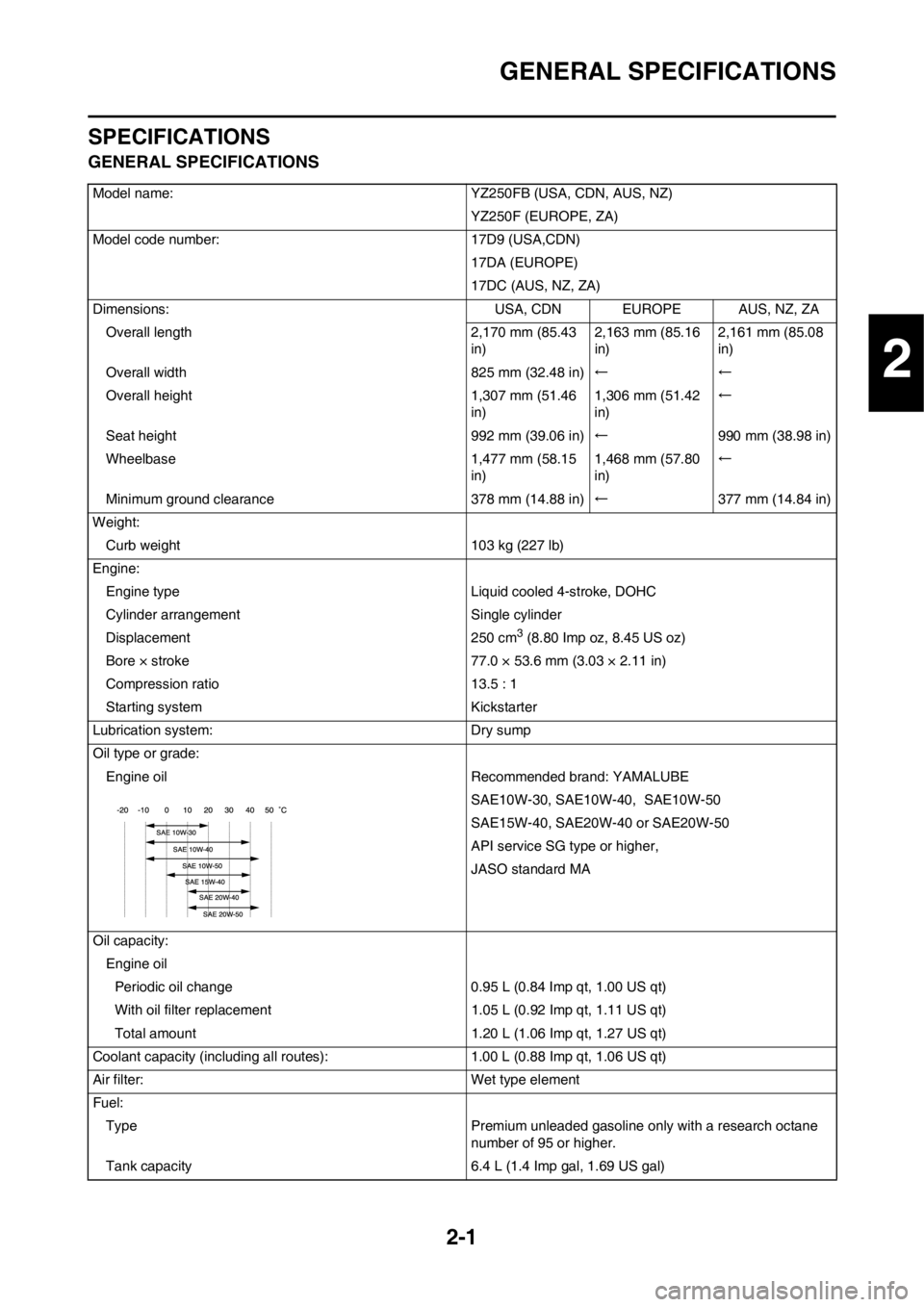
GENERAL SPECIFICATIONS
SPECIFICATIONS
GENERAL SPECIFICATIONS
Model name: YZ250FB (USA, CDN, AUS, NZ)
YZ250F (EUROPE, ZA)
Model code number: 17D9 (USA,CDN)
17DA (EUROPE)
17DC (AUS, NZ, ZA)
Dimensions: USA, CDN EUROPE AUS, NZ, ZA
Overall length 2,170 mm (85.43
in)2,163 mm (85.16
in)2,161 mm (85.08
in)
Overall width 825 mm (32.48 in)←←
Overall height 1,307 mm (51.46
in)1,306 mm (51.42
in)←
Seat height 992 mm (39.06 in)←990 mm (38.98 in)
Wheelbase 1,477 mm (58.15
in)1,468 mm (57.80
in)←
Minimum ground clearance 378 mm (14.88 in)←377 mm (14.84 in)
Weight:
Curb weight 103 kg (227 lb)
Engine:
Engine type Liquid cooled 4-stroke, DOHC
Cylinder arrangement Single cylinder
Displacement 250 cm
3 (8.80 Imp oz, 8.45 US oz)
Bore × stroke 77.0 × 53.6 mm (3.03 × 2.11 in)
Compression ratio 13.5 : 1
Starting system Kickstarter
Lubrication system: Dry sump
Oil type or grade:
Engine oil Recommended brand: YAMALUBE
SAE10W-30, SAE10W-40, SAE10W-50
SAE15W-40, SAE20W-40 or SAE20W-50
API service SG type or higher,
JASO standard MA
Oil capacity:
Engine oil
Periodic oil change 0.95 L (0.84 Imp qt, 1.00 US qt)
With oil filter replacement 1.05 L (0.92 Imp qt, 1.11 US qt)
Total amount 1.20 L (1.06 Imp qt, 1.27 US qt)
Coolant capacity (including all routes): 1.00 L (0.88 Imp qt, 1.06 US qt)
Air filter: Wet type element
Fuel:
Type Premium unleaded gasoline only with a research octane
number of 95 or higher.
Tank capacity 6.4 L (1.4 Imp gal, 1.69 US gal)
2
Page 29 of 198
2-3
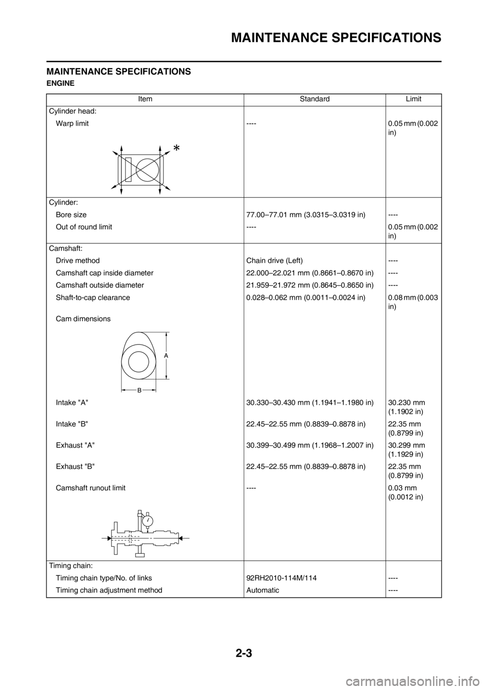
MAINTENANCE SPECIFICATIONS
MAINTENANCE SPECIFICATIONS
ENGINE
Item Standard Limit
Cylinder head:
Warp limit ---- 0.05 mm (0.002
in)
Cylinder:
Bore size 77.00–77.01 mm (3.0315–3.0319 in) ----
Out of round limit ---- 0.05 mm (0.002
in)
Camshaft:
Drive method Chain drive (Left) ----
Camshaft cap inside diameter 22.000–22.021 mm (0.8661–0.8670 in) ----
Camshaft outside diameter 21.959–21.972 mm (0.8645–0.8650 in) ----
Shaft-to-cap clearance 0.028–0.062 mm (0.0011–0.0024 in) 0.08 mm (0.003
in)
Cam dimensions
Intake "A" 30.330–30.430 mm (1.1941–1.1980 in) 30.230 mm
(1.1902 in)
Intake "B" 22.45–22.55 mm (0.8839–0.8878 in) 22.35 mm
(0.8799 in)
Exhaust "A" 30.399–30.499 mm (1.1968–1.2007 in) 30.299 mm
(1.1929 in)
Exhaust "B" 22.45–22.55 mm (0.8839–0.8878 in) 22.35 mm
(0.8799 in)
Camshaft runout limit ---- 0.03 mm
(0.0012 in)
Timing chain:
Timing chain type/No. of links 92RH2010-114M/114 ----
Timing chain adjustment method Automatic ----
Page 33 of 198

2-7
MAINTENANCE SPECIFICATIONS
Clutch:
Friction plate thickness 2.9–3.1 mm (0.114–0.122 in) 2.8 mm (0.110
in)
Quantity 9 ----
Clutch plate thickness 1.1–1.3 mm (0.043–0.051 in) ----
Quantity 8 ----
Warp limit ---- 0.1 mm (0.004
in)
Clutch spring free length 35.7 mm (1.41 in) 34.7 mm (1.37
in)
Quantity 5 ----
Clutch housing thrust clearance 0.050–0.300 mm (0.0020–0.0118 in) ----
Clutch housing radial clearance 0.010–0.044 mm (0.0004–0.0017 in) ----
Clutch release method Inner push, cam push ----
Shifter:
Shifter type Cam drum and guide bar ----
Guide bar bending limit ---- 0.05 mm (0.002
in)
Kickstarter:
Type Kick and ratchet type ----
Carburetor: USA, CDN, AUS,
NZ, ZAEUROPE
Type/manufacturer FCR-MX39/KEIHIN←----
I. D. mark 17D9 90 17DA A0 ----
Main jet (M.J) #185←----
Main air jet (M.A.J) ø2.0←----
Jet needle-clip position (J.N) NFPR-5 NFPQ-5 ----
Cutaway (C.A) 1.5←----
Pilot jet (P.J) #38←----
Pilot air jet (P.A.J) #100←----
Pilot outlet (P.O) ø0.9←----
Pilot screw (example) (P.S) 2 2-1/4 ----
Bypass (B.P) ø1.0←----
Valve seat size (V.S) ø3.8←----
Starter jet (G.S) #72←----
Leak jet (Acc.P) #95←----
Float height (F.H) 6 mm (0.24 in)←----
Engine idle speed 1,900–2,100 r/min←----
Intake vacuum 29.3–34.7 kPa
(220–260 mmHg,
8.7–10.2 inHg)←----
Hot starter lever free play 3–6 mm (0.12–0.24
in)←---- Item Standard Limit
Page 36 of 198
2-10
TIGHTENING TORQUES
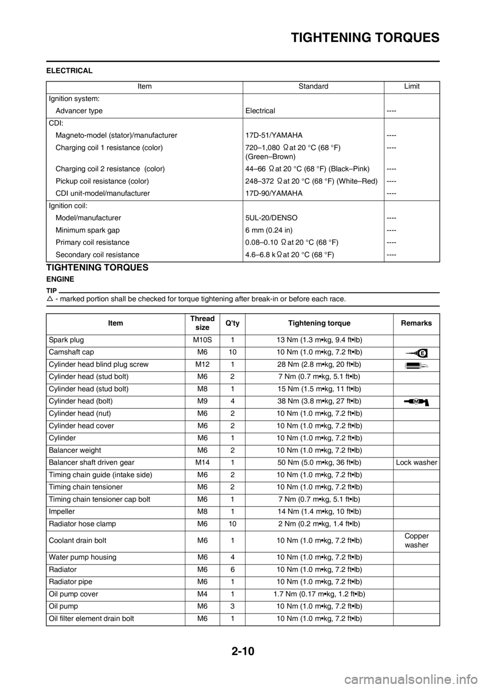
ELECTRICAL
TIGHTENING TORQUES
ENGINE
△- marked portion shall be checked for torque tightening after break-in or before each race.
Item Standard Limit
Ignition system:
Advancer type Electrical ----
CDI:
Magneto-model (stator)/manufacturer 17D-51/YAMAHA ----
Charging coil 1 resistance (color) 720–1,080 Ωat 20 °C (68 °F)
(Green–Brown)----
Charging coil 2 resistance (color) 44–66 Ωat 20 °C (68 °F) (Black–Pink) ----
Pickup coil resistance (color) 248–372 Ωat 20 °C (68 °F) (White–Red) ----
CDI unit-model/manufacturer 17D-90/YAMAHA ----
Ignition coil:
Model/manufacturer 5UL-20/DENSO ----
Minimum spark gap 6 mm (0.24 in) ----
Primary coil resistance 0.08–0.10 Ωat 20 °C (68 °F) ----
Secondary coil resistance 4.6–6.8 kΩat 20 °C (68 °F) ----
ItemThread
sizeQ'ty Tightening torque Remarks
Spark plug M10S 1 13 Nm (1.3 m•kg, 9.4 ft•lb)
Camshaft cap M6 10 10 Nm (1.0 m•kg, 7.2 ft•lb)
Cylinder head blind plug screw M12 1 28 Nm (2.8 m•kg, 20 ft•lb)
Cylinder head (stud bolt) M6 2 7 Nm (0.7 m•kg, 5.1 ft•lb)
Cylinder head (stud bolt) M8 1 15 Nm (1.5 m•kg, 11 ft•lb)
Cylinder head (bolt) M9 4 38 Nm (3.8 m•kg, 27 ft•lb)
Cylinder head (nut) M6 2 10 Nm (1.0 m•kg, 7.2 ft•lb)
Cylinder head cover M6 2 10 Nm (1.0 m•kg, 7.2 ft•lb)
Cylinder M6 1 10 Nm (1.0 m•kg, 7.2 ft•lb)
Balancer weight M6 2 10 Nm (1.0 m•kg, 7.2 ft•lb)
Balancer shaft driven gear M14 1 50 Nm (5.0 m•kg, 36 ft•lb) Lock washer
Timing chain guide (intake side) M6 2 10 Nm (1.0 m•kg, 7.2 ft•lb)
Timing chain tensioner M6 2 10 Nm (1.0 m•kg, 7.2 ft•lb)
Timing chain tensioner cap bolt M6 1 7 Nm (0.7 m•kg, 5.1 ft•lb)
Impeller M8 1 14 Nm (1.4 m•kg, 10 ft•lb)
Radiator hose clamp M6 10 2 Nm (0.2 m•kg, 1.4 ft•lb)
Coolant drain bolt M6 1 10 Nm (1.0 m•kg, 7.2 ft•lb)Copper
washer
Water pump housing M6 4 10 Nm (1.0 m•kg, 7.2 ft•lb)
Radiator M6 6 10 Nm (1.0 m•kg, 7.2 ft•lb)
Radiator pipe M6 1 10 Nm (1.0 m•kg, 7.2 ft•lb)
Oil pump cover M4 1 1.7 Nm (0.17 m•kg, 1.2 ft•lb)
Oil pump M6 3 10 Nm (1.0 m•kg, 7.2 ft•lb)
Oil filter element drain bolt M6 1 10 Nm (1.0 m•kg, 7.2 ft•lb)
Page 39 of 198
2-13
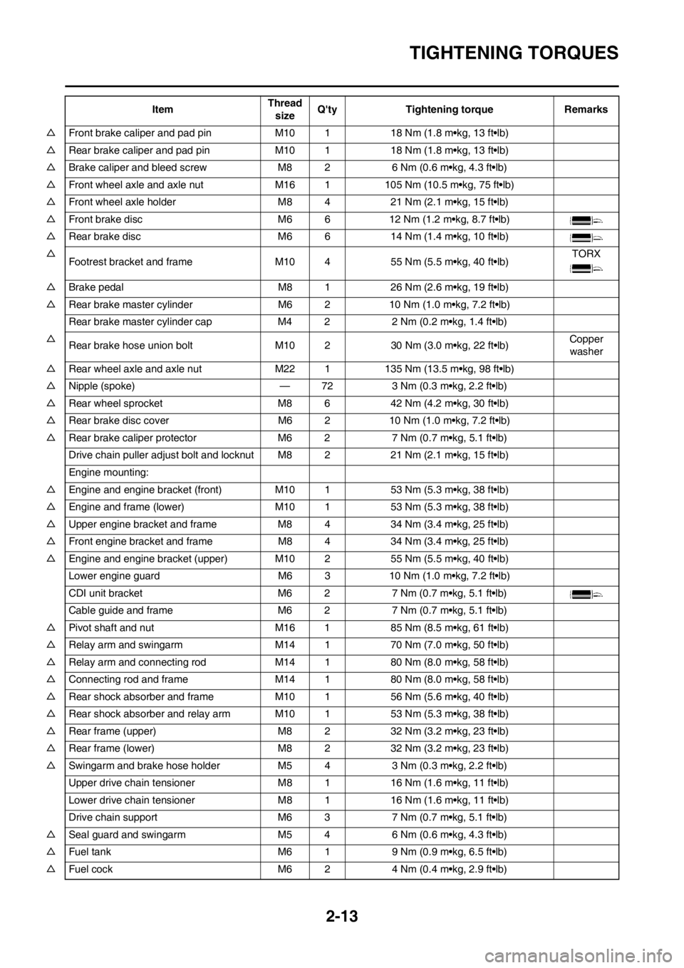
TIGHTENING TORQUES
△Front brake caliper and pad pin M10 1 18 Nm (1.8 m•kg, 13 ft•lb)
△Rear brake caliper and pad pin M10 1 18 Nm (1.8 m•kg, 13 ft•lb)
△Brake caliper and bleed screw M8 2 6 Nm (0.6 m•kg, 4.3 ft•lb)
△Front wheel axle and axle nut M16 1 105 Nm (10.5 m•kg, 75 ft•lb)
△Front wheel axle holder M8 4 21 Nm (2.1 m•kg, 15 ft•lb)
△Front brake disc M6 6 12 Nm (1.2 m•kg, 8.7 ft•lb)
△Rear brake disc M6 6 14 Nm (1.4 m•kg, 10 ft•lb)
△
Footrest bracket and frame M10 4 55 Nm (5.5 m•kg, 40 ft•lb)TORX
△Brake pedal M8 1 26 Nm (2.6 m•kg, 19 ft•lb)
△Rear brake master cylinder M6 2 10 Nm (1.0 m•kg, 7.2 ft•lb)
Rear brake master cylinder cap M4 2 2 Nm (0.2 m•kg, 1.4 ft•lb)
△
Rear brake hose union bolt M10 2 30 Nm (3.0 m•kg, 22 ft•lb)Copper
washer
△Rear wheel axle and axle nut M22 1 135 Nm (13.5 m•kg, 98 ft•lb)
△Nipple (spoke) — 72 3 Nm (0.3 m•kg, 2.2 ft•lb)
△Rear wheel sprocket M8 6 42 Nm (4.2 m•kg, 30 ft•lb)
△Rear brake disc cover M6 2 10 Nm (1.0 m•kg, 7.2 ft•lb)
△Rear brake caliper protector M6 2 7 Nm (0.7 m•kg, 5.1 ft•lb)
Drive chain puller adjust bolt and locknut M8 2 21 Nm (2.1 m•kg, 15 ft•lb)
Engine mounting:
△Engine and engine bracket (front) M10 1 53 Nm (5.3 m•kg, 38 ft•lb)
△Engine and frame (lower) M10 1 53 Nm (5.3 m•kg, 38 ft•lb)
△Upper engine bracket and frame M8 4 34 Nm (3.4 m•kg, 25 ft•lb)
△Front engine bracket and frame M8 4 34 Nm (3.4 m•kg, 25 ft•lb)
△Engine and engine bracket (upper) M10 2 55 Nm (5.5 m•kg, 40 ft•lb)
Lower engine guard M6 3 10 Nm (1.0 m•kg, 7.2 ft•lb)
CDI unit bracket M6 2 7 Nm (0.7 m•kg, 5.1 ft•lb)
Cable guide and frame M6 2 7 Nm (0.7 m•kg, 5.1 ft•lb)
△Pivot shaft and nut M16 1 85 Nm (8.5 m•kg, 61 ft•lb)
△Relay arm and swingarm M14 1 70 Nm (7.0 m•kg, 50 ft•lb)
△Relay arm and connecting rod M14 1 80 Nm (8.0 m•kg, 58 ft•lb)
△Connecting rod and frame M14 1 80 Nm (8.0 m•kg, 58 ft•lb)
△Rear shock absorber and frame M10 1 56 Nm (5.6 m•kg, 40 ft•lb)
△Rear shock absorber and relay arm M10 1 53 Nm (5.3 m•kg, 38 ft•lb)
△Rear frame (upper) M8 2 32 Nm (3.2 m•kg, 23 ft•lb)
△Rear frame (lower) M8 2 32 Nm (3.2 m•kg, 23 ft•lb)
△Swingarm and brake hose holder M54 3 Nm (0.3 m•kg, 2.2 ft•lb)
Upper drive chain tensioner M8 1 16 Nm (1.6 m•kg, 11 ft•lb)
Lower drive chain tensioner M8 1 16 Nm (1.6 m•kg, 11 ft•lb)
Drive chain support M6 3 7 Nm (0.7 m•kg, 5.1 ft•lb)
△Seal guard and swingarm M5 4 6 Nm (0.6 m•kg, 4.3 ft•lb)
△Fuel tank M6 1 9 Nm (0.9 m•kg, 6.5 ft•lb)
△Fuel cock M6 2 4 Nm (0.4 m•kg, 2.9 ft•lb)ItemThread
sizeQ'ty Tightening torque Remarks
Page 41 of 198
2-15
TIGHTENING TORQUES
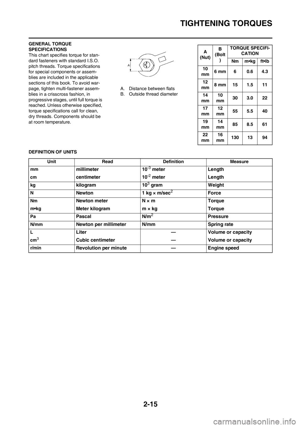
GENERAL TORQUE
SPECIFICATIONS
This chart specifies torque for stan-
dard fasteners with standard I.S.O.
pitch threads. Torque specifications
for special components or assem-
blies are included in the applicable
sections of this book. To avoid war-
page, tighten multi-fastener assem-
blies in a crisscross fashion, in
progressive stages, until full torque is
reached. Unless otherwise specified,
torque specifications call for clean,
dry threads. Components should be
at room temperature.A. Distance between flats
B. Outside thread diameter
DEFINITION OF UNITS
A
(Nut)B
(Bolt
)TORQUE SPECIFI-
CATION
Nm m•kg ft•lb
10
mm6 mm 6 0.6 4.3
12
mm8 mm 15 1.5 11
14
mm10
mm30 3.0 22
17
mm12
mm55 5.5 40
19
mm14
mm85 8.5 61
22
mm16
mm130 13 94
Unit Read Definition Measure
mm
millimeter 10-3 meter Length
cmcentimeter 10-2 meter Length
kgkilogram 103 gram Weight
NNewton 1 kg × m/sec2Force
NmNewton meter N × m Torque
m•kgMeter kilogram m × kg Torque
PaPascal N/m2Pressure
N/mmNewton per millimeter N/mm Spring rate
LLiter — Volume or capacity
cm3Cubic centimeter — Volume or capacity
r/minRevolution per minute — Engine speed
Page 47 of 198

2-21
CABLE ROUTING DIAGRAM
A. Pass the hot starter cable over
the radiator mounting boss.
B. Pass the throttle position sensor
lead under the hot starter cable.
C. Fasten the throttle position sen-
sor lead and the hot starter ca-
ble.
D. Locate the clamp between the
hot starter cable protector and
rubber cap.
E. Fasten the neutral switch lead
below the oil hose. and pass the
neutral switch lead on the inside
of the oil hose.
F. Pass the neutral switch lead on
the inside of the oil hose.
G. Fasten the neutral switch lead,
CDI magneto lead, and radiator
breather hose onto the frame.
They should all be clamped
above the engine bracket to the
left of the downtube of the
frame. The clamp ends should
face backward and the rest out-
side of the frame.
H. Pass the clutch cable through
the cable guide.
I. Pass the neutral switch lead and
CDI magneto lead behind the
frame.
J. Pass the hot starter cable on the
inside of the cylinder head
breather hose.
K. Fit the coupler projection into the
hole in the cover.
L. Fasten the sub-wire harness on
the CDI unit bracket.
M. Fasten the sub-wire harness at
the position-taped portion.
N. Pass each lead under the
clamp. Locate the CDI magneto
lead on the outside of the igni-
tion coil lead. Locate the throttle
position sensor lead, neutral
switch lead, CDI magneto lead
and ignition coil lead so that they
do not lie one on another.
O. Fasten the sub-wire harness to
the CDI unit bracket with the
clamp ends located under the
bracket.
P. Fasten the neutral switch lead,
throttle position sensor lead,
CDI magneto lead and ignition
coil lead. Fasten them around
the periphery of the recess be-
tween the tension pipe and radi-
ator mounting boss on the
frame.
Q. Locate the clamp ends within
the arrowed range. Assure that
the clamp end does not contact
the cylinder head breather hose.R. Pass the radiator breather hose
on the outside of the CDI mag-
neto lead and neutral switch
lead.
S. Fasten the throttle position sen-
sor lead and hot starter cable.
Fasten them between the cylin-
der head breather hose and
throttle position sensor tube
clamp. Fasten the clamp with its
ends toward the right-side of the
frame and cut off the other end
with 3 to 5 clamp holes left in it.
T. Locate the radiator breather
hose end above the down tube
and between the oil hose and
engine guard.
U. Fasten the neutral switch lead
above the oil hose, and pass the
neutral switch lead on the inside
of the oil hose.
Page 48 of 198
2-22
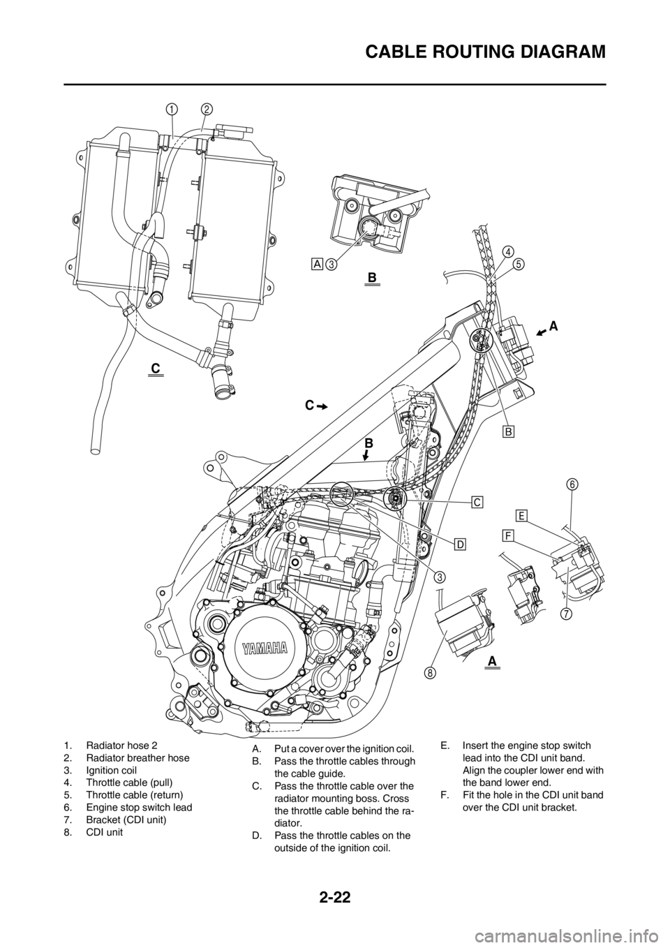
CABLE ROUTING DIAGRAM
1. Radiator hose 2
2. Radiator breather hose
3. Ignition coil
4. Throttle cable (pull)
5. Throttle cable (return)
6. Engine stop switch lead
7. Bracket (CDI unit)
8. CDI unitA. Put a cover over the ignition coil.
B. Pass the throttle cables through
the cable guide.
C. Pass the throttle cable over the
radiator mounting boss. Cross
the throttle cable behind the ra-
diator.
D. Pass the throttle cables on the
outside of the ignition coil.E. Insert the engine stop switch
lead into the CDI unit band.
Align the coupler lower end with
the band lower end.
F. Fit the hole in the CDI unit band
over the CDI unit bracket.
CA
BB
A
C