Cables YAMAHA YZ250F 2013 Owners Manual
[x] Cancel search | Manufacturer: YAMAHA, Model Year: 2013, Model line: YZ250F, Model: YAMAHA YZ250F 2013Pages: 198, PDF Size: 11.66 MB
Page 26 of 198

1-16
CLEANING AND STORAGE
CLEANING AND STORAGE
CLEANING
Frequent cleaning of your machine
will enhance its appearance, maintain
good overall performance, and ex-
tend the life of many components.
1. Before washing the machine,
block off the end of the exhaust
pipe to prevent water from enter-
ing. A plastic bag secured with a
rubber band may be used for this
purpose.
2. If the engine is excessively
greasy, apply some degreaser to
it with a paint brush. Do not apply
degreaser to the chain, sprockets,
or wheel axles.
3. Rinse the dirt and degreaser off
with a garden hose; use only
enough pressure to do the job.
Do not use high-pressure washers
or steam-jet cleaners since they
cause water seepage and deterio-
ration seals.
4. After the majority of the dirt has
been hosed off, wash all surfaces
with warm water and a mild deter-
gent. Use an old toothbrush to
clean hard-to-reach places.
5. Rinse the machine off immediate-
ly with clean water, and dry all
surfaces with a soft towel or cloth.
6. Immediately after washing, re-
move excess water from the
chain with a paper towel and lubri-
cate the chain to prevent rust.
7. Clean the seat with a vinyl uphol-
stery cleaner to keep the cover
pliable and glossy.
8. Automotive wax may be applied
to all painted or chromed surfac-
es. Avoid combination cleaner-
waxes, as they may contain abra-
sives.
9. After completing the above, start
the engine and allow it to idle for
several minutes.STORAGE
If your machine is to be stored for 60
days or more, some preventive mea-
sures must be taken to avoid deterio-
ration. After cleaning the machine
thoroughly, prepare it for storage as
follows:
1. Drain the fuel tank, fuel lines, and
the carburetor float bowl.
2. Remove the spark plug, pour a ta-
blespoon of SAE 10W-40 motor
oil in the spark plug hole, and re-
install the plug. With the engine
stop switch pushed in, kick the en-
gine over several times to coat the
cylinder walls with oil.
3. Remove the drive chain, clean it
thoroughly with solvent, and lubri-
cate it. Reinstall the chain or store
it in a plastic bag tied to the frame.
4. Lubricate all control cables.
5. Block the frame up to raise the
wheels off the ground.
6. Tie a plastic bag over the exhaust
pipe outlet to prevent moisture
from entering.
7. If the machine is to be stored in a
humid or salt-air environment,
coat all exposed metal surfaces
with a film of light oil. Do not apply
oil to rubber parts or the seat cov-
er.
Make any necessary repairs before
the machine is stored.
Page 48 of 198
2-22
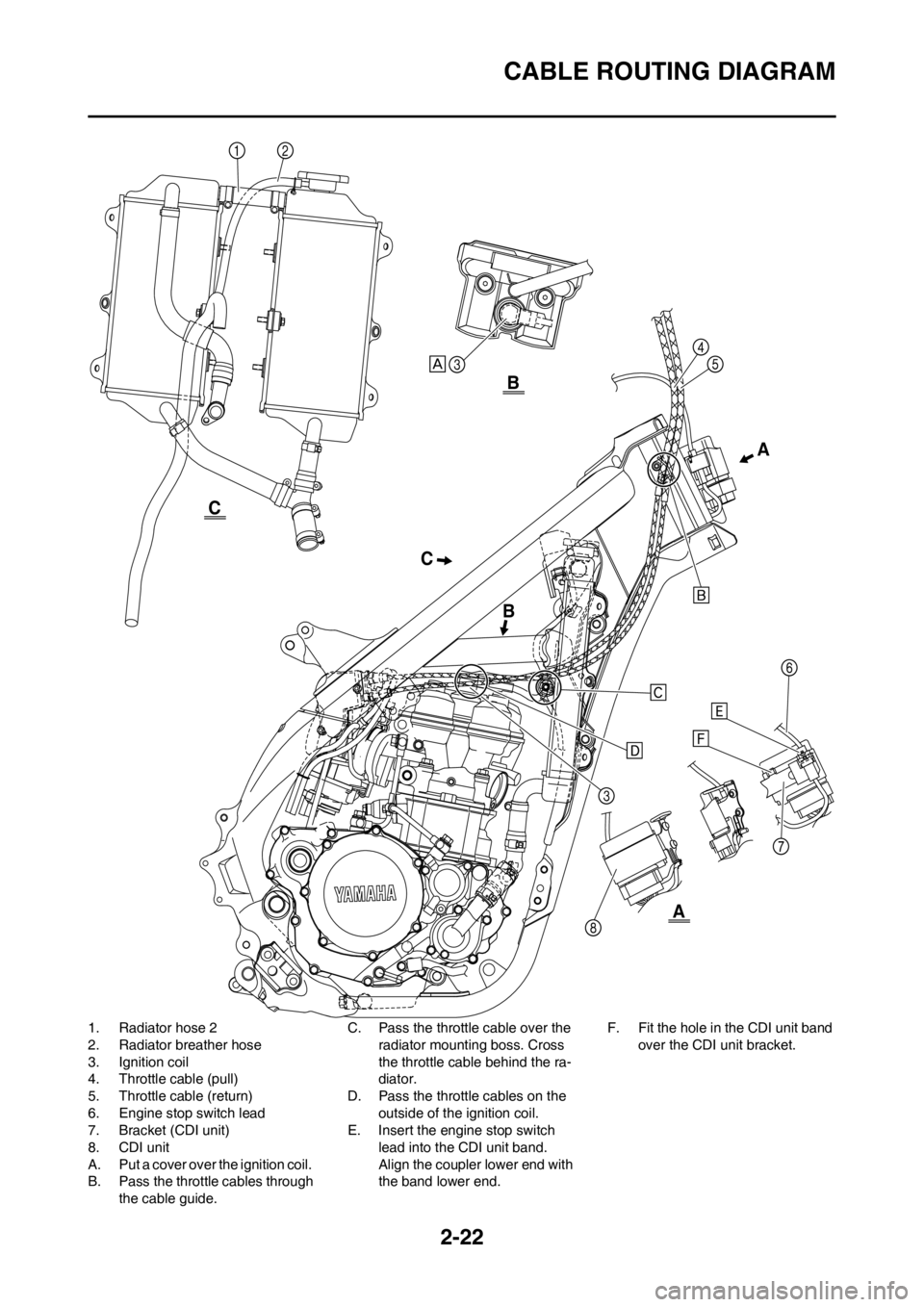
CABLE ROUTING DIAGRAM
1. Radiator hose 2
2. Radiator breather hose
3. Ignition coil
4. Throttle cable (pull)
5. Throttle cable (return)
6. Engine stop switch lead
7. Bracket (CDI unit)
8. CDI unit
A. Put a cover over the ignition coil.
B. Pass the throttle cables through
the cable guide.C. Pass the throttle cable over the
radiator mounting boss. Cross
the throttle cable behind the ra-
diator.
D. Pass the throttle cables on the
outside of the ignition coil.
E. Insert the engine stop switch
lead into the CDI unit band.
Align the coupler lower end with
the band lower end.F. Fit the hole in the CDI unit band
over the CDI unit bracket.
CA
BB
A
C
Page 50 of 198

2-24
CABLE ROUTING DIAGRAM
1. Throttle cable
2. Clamp
3. Hot starter cable
4. Clutch cable
5. Engine stop switch lead
6. Cable guide
7. Brake hose
8. Hose guideA. Fasten the engine stop switch
lead to the handlebar.
B. Pass the clutch cable and hot
starter cable through the cable
guide.
C. Pass the engine stop switch
lead behind the CDI unit.D. Pass the brake hose in front of
the number plate.
E. Pass the throttle cables through
the cable guide.
F. Pass the clutch cable and hot
starter cable through the cable
guide on the number plate.
G. Pass the engine stop switch
lead over the number plate
mounting location.
A
CB
C
B
A
Page 55 of 198
3-5
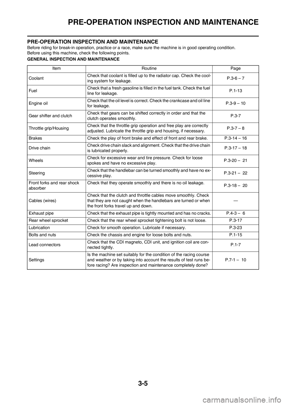
PRE-OPERATION INSPECTION AND MAINTENANCE
PRE-OPERATION INSPECTION AND MAINTENANCE
Before riding for break-in operation, practice or a race, make sure the machine is in good operating condition.
Before using this machine, check the following points.
GENERAL INSPECTION AND MAINTENANCE
Item Routine Page
CoolantCheck that coolant is filled up to the radiator cap. Check the cool-
ing system for leakage.P.3-6 – 7
FuelCheck that a fresh gasoline is filled in the fuel tank. Check the fuel
line for leakage.P.1-13
Engine oilCheck that the oil level is correct. Check the crankcase and oil line
for leakage.P.3-9 – 10
Gear shifter and clutchCheck that gears can be shifted correctly in order and that the
clutch operates smoothly.P.3-7
Throttle grip/HousingCheck that the throttle grip operation and free play are correctly
adjusted. Lubricate the throttle grip and housing, if necessary.P.3-7 – 8
Brakes Check the play of front brake and effect of front and rear brake. P.3-14 – 16
Drive chainCheck drive chain slack and alignment. Check that the drive chain
is lubricated properly.P.3-17 – 18
WheelsCheck for excessive wear and tire pressure. Check for loose
spokes and have no excessive play.P.3-20 – 21
SteeringCheck that the handlebar can be turned smoothly and have no ex-
cessive play.P.3-21 – 22
Front forks and rear shock
absorberCheck that they operate smoothly and there is no oil leakage.
P.3-18 – 20
Cables (wires)Check that the clutch and throttle cables move smoothly. Check
that they are not caught when the handlebars are turned or when
the front forks travel up and down.—
Exhaust pipe Check that the exhaust pipe is tightly mounted and has no cracks. P.4-3 – 6
Rear wheel sprocket Check that the rear wheel sprocket tightening bolt is not loose. P.3-17
Lubrication Check for smooth operation. Lubricate if necessary. P.3-23
Bolts and nuts Check the chassis and engine for loose bolts and nuts. P.1-15
Lead connectorsCheck that the CDI magneto, CDI unit, and ignition coil are con-
nected tightly.P.1-7
SettingsIs the machine set suitably for the condition of the racing course
and weather or by taking into account the results of test runs be-
fore racing? Are inspection and maintenance completely done?P.7-1 – 10
Page 129 of 198

4-55
ENGINE REMOVAL
HANDLING NOTE
Support the machine securely so
there is no danger of it falling over.
REMOVING THE DRIVE
SPROCKET
1. Remove:
• Nut (drive sprocket) "1"
• Lock washer "2"
• Straighten the lock washer tab.
• Loosen the nut while applying the
rear brake.
2. Remove:
• Drive sprocket "1"
• Drive chain "2"
Remove the drive sprocket together
with the drive chain.
REMOVING THE ENGINE
1. Remove:
• Pivot shaft "1"
If the pivot shaft is pulled all the way
out, the swingarm will come loose. If
possible, insert a shaft of similar di-
ameter into the other side of the
swingarm to support it.
2. Remove:
• Engine "1"
From right side.
Make sure that the couplers, hoses
and cables are disconnected.
INSTALLING THE ENGINE
1. Install:
• Engine "1"
Install the engine from right side.
• Pivot shaft "2"
• Engine mounting bolt (lower) "3"
• Front engine bracket "4"
• Bolt (front engine bracket) "5"
• Patch "6"
• Engine mounting bolt (front) "7"
• Upper engine bracket "8"
• Bolt (upper engine bracket) "9"
• Engine mounting bolt (upper) "10"• Lower engine guard "11"
• Bolt (lower engine guard) "12"
• Apply the molybdenum disulfide
grease on the pivot shaft.
• Install the patch with the claw "a"
facing outside the chassis.
INSTALLING THE BRAKE PEDAL
1. Install:
• Spring "1"
• Brake pedal "2"
• O-ring "3"
• Bolt (brake pedal) "4"
• Clip "5"
Apply the lithium soap base grease
on the bolt, O-rings and brake pedal
bracket.
Pivot shaft:
85 Nm (8.5 m•kg, 61
ft•lb)
Engine mounting bolt
(lower):
53Nm (5.3 m•kg, 38
ft•lb)
Bolt (front engine brack-
et):
34 Nm (3.4 m•kg, 24
ft•lb)
Engine mounting bolt
(front):
53 Nm (5.3 m•kg, 38
ft•lb)
Bolt (upper engine brack-
et):
34 Nm (3.4 m•kg, 24
ft•lb)
Engine mounting bolt
(upper):
55 Nm (5.5 m•kg, 40
ft•lb)
Bolt (lower engine
guard):
10 Nm (1.0 m•kg, 7.2
ft•lb)
Bolt (brake pedal):
26 Nm (2.6 m•kg, 19
ft•lb)
M
Page 165 of 198

5-26
HANDLEBAR
3. Tighten:
• Nut (handlebar lower holder) "1"
4. Install:
• Left grip "1"
Apply the adhesive to the handle-
bar "2".
• Before applying the adhesive, wipe
off grease or oil on the handlebar
surface "a" with a lacquer thinner.
• Install the left grip to the handlebar
so that the line "b" between the two
arrow marks faces straight upward.
5. Install:
• Right grip "1"
•Collar "2"
Apply the adhesive on the tube
guide "3".
• Before applying the adhesive, wipe
off grease or oil on the tube guide
surface "a" with a lacquer thinner.
• Install the grip to the tube guide so
that the grip match mark "b" and
tube guide slot "c" form the angle as
shown.
6. Install:
• Collar "1"
• Grip cap cover "2"
• Throttle grip "3"
Apply the lithium soap base grease
on the throttle grip sliding surface.
7. Install:
• Throttle cables "1"
To tube guide "2".
Apply the lithium soap base grease
on the throttle cable end and tube
guide cable winding portion.
8. Install:
• Throttle cable cap "1"
• Screw (throttle cable cap) "2"
After tightening the screws, check
that the throttle grip "3" moves
smoothly. If it does not, retighten
the bolts for adjustment.
9. Install:
• Grip cap cover "1"
• Cover (throttle cable cap) "2"
10. Install:
• Brake master cylinder "1"
• Brake master cylinder bracket "2"
• Bolt (brake master cylinder brack-
et) "3"
• Install the bracket so that the arrow
mark "a" faces upward.
• First tighten the bolt on the upper
side of the brake master cylinder
bracket, and then tighten the bolt on
the lower side.
11. Install:
• Engine stop switch "1"
• Clutch lever holder "2"
• Bolt (clutch lever holder) "3"
• Hot starter lever holder "4"
• Bolt (hot starter lever holder) "5" Nut (handlebar lower
holder):
34 Nm (3.4 m•kg, 24
ft•lb)
Screw (throttle cable
cap):
4 Nm (0.4 m•kg, 2.9
ft•lb)
Bolt (brake master cylin-
der bracket):
9 Nm (0.9 m•kg, 6.5
ft•lb)
Bolt (clutch lever holder):
5 Nm (0.5 m•kg, 3.6
ft•lb)
Bolt (hot starter lever
holder):
4 Nm (0.4 m•kg, 2.9
ft•lb)