ad blue YAMAHA YZ250F 2013 Owners Manual
[x] Cancel search | Manufacturer: YAMAHA, Model Year: 2013, Model line: YZ250F, Model: YAMAHA YZ250F 2013Pages: 198, PDF Size: 11.66 MB
Page 92 of 198
4-18
CAMSHAFTS
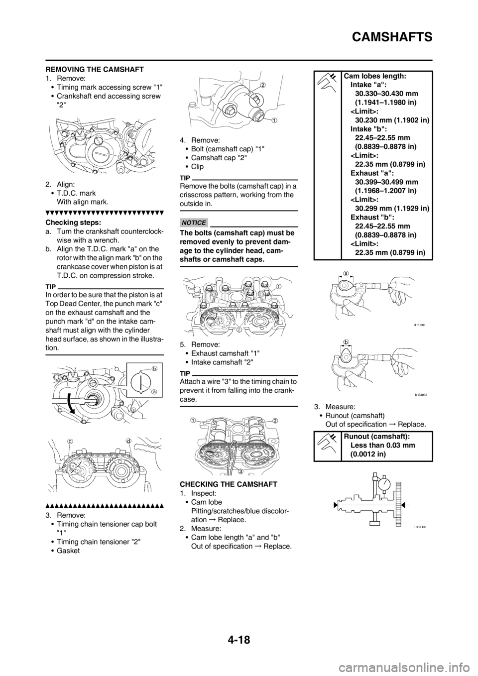
REMOVING THE CAMSHAFT
1. Remove:
• Timing mark accessing screw "1"
• Crankshaft end accessing screw
"2"
2. Align:
• T.D.C. mark
With align mark.
Checking steps:
a. Turn the crankshaft counterclock-
wise with a wrench.
b. Align the T.D.C. mark "a" on the
rotor with the align mark "b" on the
crankcase cover when piston is at
T.D.C. on compression stroke.
In order to be sure that the piston is at
Top Dead Center, the punch mark "c"
on the exhaust camshaft and the
punch mark "d" on the intake cam-
shaft must align with the cylinder
head surface, as shown in the illustra-
tion.
3. Remove:
• Timing chain tensioner cap bolt
"1"
• Timing chain tensioner "2"
• Gasket4. Remove:
• Bolt (camshaft cap) "1"
• Camshaft cap "2"
• Clip
Remove the bolts (camshaft cap) in a
crisscross pattern, working from the
outside in.
The bolts (camshaft cap) must be
removed evenly to prevent dam-
age to the cylinder head, cam-
shafts or camshaft caps.
5. Remove:
• Exhaust camshaft "1"
• Intake camshaft "2"
Attach a wire "3" to the timing chain to
prevent it from falling into the crank-
case.
CHECKING THE CAMSHAFT
1. Inspect:
• Cam lobe
Pitting/scratches/blue discolor-
ation→Replace.
2. Measure:
• Cam lobe length "a" and "b"
Out of specification→Replace.3. Measure:
• Runout (camshaft)
Out of specification→Replace.
Cam lobes length:
Intake "a":
30.330–30.430 mm
(1.1941–1.1980 in)
30.230 mm (1.1902 in)
Intake "b":
22.45–22.55 mm
(0.8839–0.8878 in)
22.35 mm (0.8799 in)
Exhaust "a":
30.399–30.499 mm
(1.1968–1.2007 in)
30.299 mm (1.1929 in)
Exhaust "b":
22.45–22.55 mm
(0.8839–0.8878 in)
22.35 mm (0.8799 in)
Runout (camshaft):
Less than 0.03 mm
(0.0012 in)
Page 99 of 198
4-25
VALVES AND VALVE SPRINGS
After replacing the valve guide reface
the valve seat.
3. Inspect:• Valve facePitting/wear →Grind the face.
• Valve stem end Mushroom shape or diameter
larger than the body of the stem →
Replace.
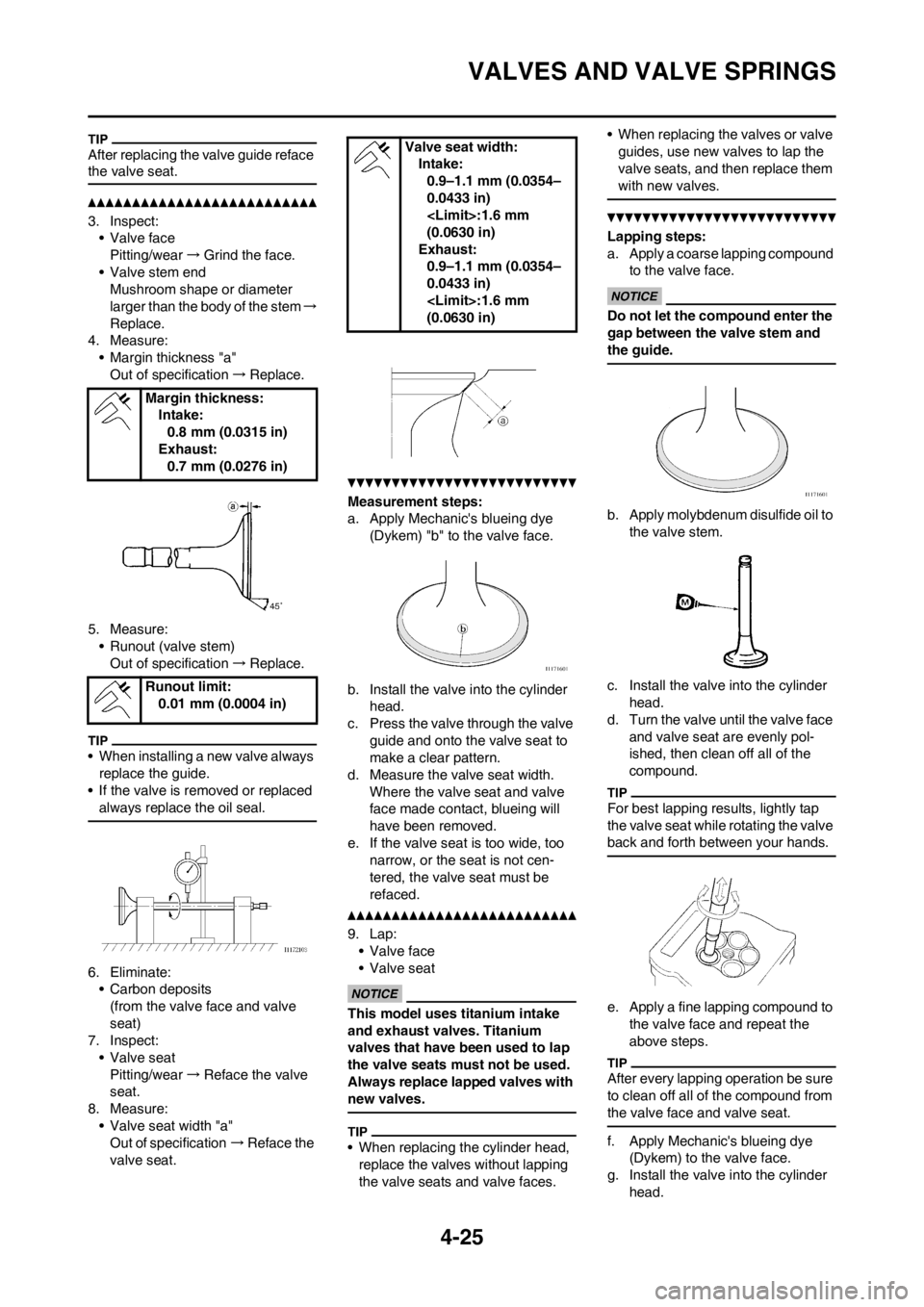
4. Measure: • Margin thickness "a"
Out of specification →Replace.
5. Measure: • Runout (valve stem)Out of specification →Replace.
• When installing a new valve always
replace the guide.
• If the valve is removed or replaced
always replace the oil seal.
6. Eliminate:• Carbon deposits
(from the valve face and valve
seat)
7. Inspect:
• Valve seatPitting/wear →Reface the valve
seat.
8. Measure: • Valve seat width "a"Out of specification →Reface the
valve seat.
Measurement steps:
a. Apply Mechanic's blueing dye (Dykem) "b" to the valve face.
b. Install the valve into the cylinder head.
c. Press the valve through the valve
guide and onto the valve seat to
make a clear pattern.
d. Measure the valve seat width.
Where the valve seat and valve
face made contact, blueing will
have been removed.
e. If the valve seat is too wide, too narrow, or the seat is not cen-
tered, the valve seat must be
refaced.
9. Lap: • Valve face
• Valve seat
This model uses titanium intake
and exhaust valves. Titanium
valves that have been used to lap
the valve seats must not be used.
Always replace lapped valves with
new valves.
• When replacing the cylinder head, replace the valves without lapping
the valve seats and valve faces. • When replacing the valves or valve
guides, use new valves to lap the
valve seats, and then replace them
with new valves.
Lapping steps:
a. Apply a coarse lapping compound to the valve face.
Do not let the co mpound enter the
gap between the valve stem and
the guide.
b. Apply molybdenum disulfide oil to
the valve stem.
c. Install the valve into the cylinder head.
d. Turn the valve until the valve face
and valve seat are evenly pol-
ished, then clean off all of the
compound.
For best lapping results, lightly tap
the valve seat while rotating the valve
back and forth between your hands.
e. Apply a fine lapping compound to the valve face and repeat the
above steps.
After every lapping operation be sure
to clean off all of the compound from
the valve face and valve seat.
f. Apply Mechanic's blueing dye (Dykem) to the valve face.
g. Install the valve into the cylinder
head.
Margin thickness:
Intake:0.8 mm (0.0315 in)
Exhaust: 0.7 mm (0.0276 in)
Runout limit: 0.01 mm (0.0004 in)
Valve seat width: Intake:0.9–1.1 mm (0.0354–
0.0433 in)
(0.0630 in)
Exhaust: 0.9–1.1 mm (0.0354–
0.0433 in)
(0.0630 in)
Page 100 of 198
4-26
VALVES AND VALVE SPRINGS
h. Press the valve through the valve guide and onto the valve seat to
make a clear pattern.
i. Measure the valve seat width again. If the valve seat width is out
of specification, reface and relap
the valve seat.
CHECKING THE VALVE SPRINGS
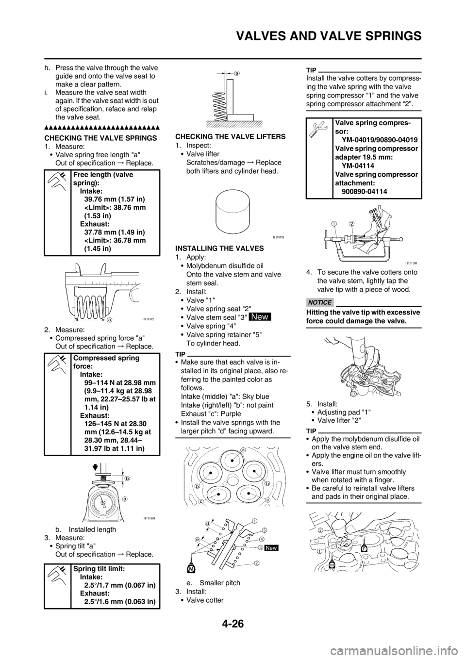
1. Measure:• Valve spring free length "a"Out of specification →Replace.
2. Measure: • Compressed spring force "a"Out of specification →Replace.
b. Installed length
3. Measure: • Spring tilt "a"Out of specification →Replace. CHECKING THE
VALVE LIFTERS
1. Inspect:
• Valve lifterScratches/damage →Replace
both lifters and cylinder head.
INSTALLING THE VALVES
1. Apply: • Molybdenum disulfide oil
Onto the valve stem and valve
stem seal.
2. Install:
• Valve "1"
• Valve spring seat "2"
• Valve stem seal "3"
• Valve spring "4"
• Valve spring retainer "5"To cylinder head.
• Make sure that each valve is in-
stalled in its original place, also re-
ferring to the painted color as
follows.
Intake (middle) "a": Sky blue
Intake (right/left) "b": not paint
Exhaust "c": Purple
• Install the valve springs with the larger pitch "d" facing upward.
e. Smaller pitch
3. Install: • Valve cotter
Install the valve cotters by compress-
ing the valve spring with the valve
spring compressor “1” and the valve
spring compressor attachment “2”.
4. To secure the valve cotters onto
the valve stem, lightly tap the
valve tip with a piece of wood.
Hitting the valve tip with excessive
force could damage the valve.
5. Install:• Adjusting pad "1"
• Valve lifter "2"
• Apply the molybdenum disulfide oil on the valve stem end.
• Apply the engine oil on the valve lift- ers.
• Valve lifter must turn smoothly when rotated with a finger.
• Be careful to reinstall valve lifters and pads in their original place.
Free length (valve
spring): Intake:39.76 mm (1.57 in)
(1.53 in)
Exhaust: 37.78 mm (1.49 in)
(1.45 in)
Compressed spring
force: Intake:99–114 N at 28.98 mm
(9.9–11.4 kg at 28.98
mm, 22.27–25.57 lb at
1.14 in)
Exhaust: 126–145 N at 28.30
mm (12.6–14.5 kg at
28.30 mm, 28.44–
31.97 lb at 1.11 in)
Spring tilt limit: Intake:2.5°/1.7 mm (0.067 in)
Exhaust: 2.5°/1.6 mm (0.063 in)
Valve spring compres-
sor:
YM-04019/90890-04019
Valve spring compressor
adapter 19.5 mm: YM-04114
Valve spring compressor
attachment: 900890-04114
Page 103 of 198
4-29
CYLINDER AND PISTON
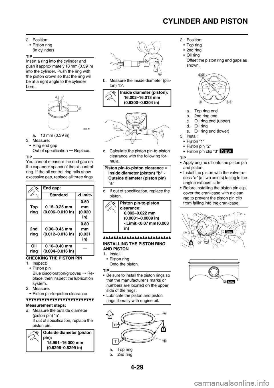
2. Position:
• Piston ring
(in cylinder)
Insert a ring into the cylinder and
push it approximately 10 mm (0.39 in)
into the cylinder. Push the ring with
the piston crown so that the ring will
be at a right angle to the cylinder
bore.
a. 10 mm (0.39 in)
3. Measure:
• Ring end gap
Out of specification→Replace.
You cannot measure the end gap on
the expander spacer of the oil control
ring. If the oil control ring rails show
excessive gap, replace all three rings.
CHECKING THE PISTON PIN
1. Inspect:
• Piston pin
Blue discoloration/grooves→Re-
place, then inspect the lubrication
system.
2. Measure:
• Piston pin-to-piston clearance
Measurement steps:
a. Measure the outside diameter
(piston pin) "a".
If out of specification, replace the
piston pin.b. Measure the inside diameter (pis-
ton) "b".
c. Calculate the piston pin-to-piston
clearance with the following for-
mula.
d. If out of specification, replace the
piston.
INSTALLING THE PISTON RING
AND PISTON
1. Install:
•Piston ring
Onto the piston.
• Be sure to install the piston rings so
that the manufacturer's marks or
numbers are located on the upper
side of the rings.
• Lubricate the piston and piston
rings liberally with engine oil.
a. Top ring
b. 2nd ring2. Position:
•Top ring
•2nd ring
•Oil ring
Offset the piston ring end gaps as
shown.
a. Top ring end
b. 2nd ring end
c. Oil ring end (upper)
d. Oil ring
e. Oil ring end (lower)
3. Install:
• Piston "1"
• Piston pin "2"
• Piston pin clip "3"
• Apply engine oil onto the piston pin
and piston.
• Install the piston with the valve re-
cess "a" (at two points) facing to the
engine exhaust side.
• Before installing the piston pin clip,
cover the crankcase with a clean
rag to prevent the piston pin clip
from falling into the crankcase.
End gap:
Standard
Top
ring0.15–0.25 mm
(0.006–0.010 in)0.50
mm
(0.020
in)
2nd
ring0.30–0.45 mm
(0.012–0.018 in)0.80
mm
(0.031
in)
Oil
ring0.10–0.40 mm
(0.004–0.016 in)—
Outside diameter (piston
pin):
15.991–16.000 mm
(0.6296–0.6299 in)
Inside diameter (piston):
16.002–16.013 mm
(0.6300–0.6304 in)
Piston pin-to-piston clearance =
Inside diameter (piston) "b" -
Outside diameter (piston pin)
"a"
Piston pin-to-piston
clearance:
0.002–0.022 mm
(0.0001–0.0009 in)
in)
Page 180 of 198

6-2
ELECTRICAL COMPONENTS AND WIRING DIAGRAM
ELECTRICAL
COMPONENTS AND
WIRING DIAGRAM
ELECTRICAL COMPONENTS
1. Engine stop switch
2. Throttle position sensor
3. Neutral switch4. CDI magneto
5. Ignition coil
6. Spark plug7. CDI unit
WIRING DIAGRAM
1. Engine stop switch
2. Throttle position sensor
3. Neutral switch
4. CDI magneto
5. Ignition coil
6. Spark plug
7. CDI unit COLOR CODE
BBlack
Br Brown
GGreen
LBlue
O Orange
PPink
RRed
Sb Sky blue
WWhite
YYellowB/L Black/Blue
B/W Black/White
B/Y Black/Yellow
G/B Green/Black
L/W Blue/White
R/W Red/White
B/WB/W
B/L
B/Y
SbSb
G/B
LYLY
P
B
B
B
B
G
O
WR
P
GW
R
P
B
Br W
W
B/Y G Br
G
RR
OB
Sb Sb
Y
Y
W Y
W
GG B
P P
Br BrRR
O L
B
Sb Y
LL
B/L
B/W
B/W
G/B
B
B
B/L
L
Sb
B/L
G/B
G/B B/Y
B/Y
B/W O
B/W
BrBrP
Page 183 of 198
6-5
IGNITION SYSTEM
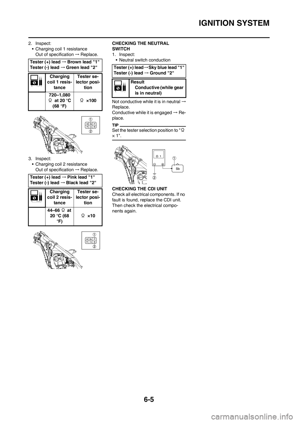
2. Inspect:
• Charging coil 1 resistance
Out of specification→Replace.
3. Inspect:
• Charging coil 2 resistance
Out of specification→Replace.CHECKING THE NEUTRAL
SWITCH
1. Inspect:
• Neutral switch conduction
Not conductive while it is in neutral→
Replace.
Conductive while it is engaged→Re-
place.
Set the tester selection position to "Ω
× 1".
CHECKING THE CDI UNIT
Check all electrical components. If no
fault is found, replace the CDI unit.
Then check the electrical compo-
nents again. Tester (+) lead→Brown lead "1"
Tester (-) lead→Green lead "2"
Charging
coil 1 resis-
tanceTester se-
lector posi-
tion
720–1,080
Ω at 20 °C
(68 °F)Ω ×100
Tester (+) lead→Pink lead "1"
Tester (-) lead→Black lead "2"
Charging
coil 2 resis-
tanceTester se-
lector posi-
tion
44–66 Ω at
20 °C (68
°F)Ω ×10
B WBr
GP
R
B WBr
GP
R
Tester (+) lead→Sky blue lead "1"
Tester (-) lead→Ground "2"
Result
Conductive (while gear
is in neutral)
Page 185 of 198

6-7
THROTTLE POSITION SENSOR SYSTEM
HANDLING NOTE
Do not loosen the screw (throttle
position sensor) "1" except when
changing the throttle position sen-
sor due to failure because it will
cause a drop in engine perfor-
mance.
CHECKING THE COUPLERS AND
LEADS CONNECTION
1. Check:
• Couplers and leads connection
Rust/dust/looseness/short-circuit
→Repair or replace.
CHECKING THE THROTTLE
POSITION SENSOR COIL
1. Inspect:
• Throttle position sensor coil resis-
tance
Out of specification→Replace.
2. Loosen:
• Throttle stop screw "1"
Turn out the throttle stop screw until
the throttle shaft is in the full close po-
sition.
3. Inspect:
• Throttle position sensor coil vari-
able resistance
Check that the resistance in in-
creased as the throttle grip is
moved from the full close position
to the full open position.
Out of specification→Replace.
CHANGING AND ADJUSTING THE
THROTTLE POSITION SENSOR
1. Remove:
• Throttle position sensor coupler
• Carburetor
2. Remove:
• Screw (throttle position sensor)
"1"
• Throttle position sensor "2"
Loosen the screw (throttle position
sensor) using the T25 bit.
3. Replace:
• Throttle position sensor4. Install:
• Throttle position sensor "1"
• Screw (throttle position sensor)
"2"
• Align the slot "a" in the throttle posi-
tion sensor with the projection "b"
on the carburetor.
• Temporarily tighten the screw
(throttle position sensor).
5. Install:
•Carburetor
• Throttle position sensor coupler
6. Adjust:
• Engine idling speed
Refer to "ADJUSTING THE EN-
GINE IDLING SPEED" section in
the CHAPTER 3.
7. Insert the thin electric conductors
"2" (lead) into the throttle position
sensor coupler "1", as shown, and
connect the tester to them.
• Do not insert the electric conduc-
tors more than required because
it may reduce the waterproof
function of the coupler.
• Make sure that a short-circuit
does not develop between the
terminals because it may cause
damage to electrical compo-
nents.
Tester (+) lead→Blue lead "1"
Tester (-) lead→Black lead "2"
Throttle po-
sition sen-
sor coil
resistanceTester se-
lector posi-
tion
4–6 kΩ at
20°C (68 °F) kΩ×1
Y
B L
Tester (+) lead→Yellow lead "1"
Tester (-) lead→Black lead "2"
Throttle position
sensor coil vari-
able resistanceTes-
ter se-
lector
posi-
tion
Full
closedFull
opened
kΩ×1 0–3
kΩat
20°C
(68 °F)4–6
kΩat
20 °C
(68 °F)
Y
B L
Tester (+) lead→Yellow lead "3"
Tester (-) lead→Black lead "4"
Page 186 of 198

6-8
THROTTLE POSITION SENSOR SYSTEM
8. Start the engine.
9. Adjust:
• Throttle position sensor output
voltage
Adjustment steps:
a. Adjust the installation angle of the
throttle position sensor "1" to ob-
tain the specified output voltage.
Measure the output voltage accurate-
ly with a digital electronic voltmeter
that gives an easy reading of a small
voltage.
10. Put the aligning marks "a" on the
throttle position sensor and car-
buretor.
11. Stop the engine.
12. Remove the carburetor.
13. Tighten:
• Screw (throttle position sensor)
"1"
Tighten the screw (throttle position
sensor) using the T25 bit.
14. Install the carburetor.CHECKING THE THROTTLE
POSITION SENSOR INPUT
VOLTAGE
1. Disconnect the throttle position
sensor coupler.
2. Start the engine.
3. Inspect:
• Throttle position sensor input volt-
age
Out of specification→Replace the
CDI unit.
Throttle po-
sition sen-
sor output
voltageTester se-
lector posi-
tion
0.58–0.78 V DCV
Tester (+) lead→Blue lead "1"
Tester (-) lead→Black/Blue lead
"2"
Throttle po-
sition sen-
sor input
voltage Tester se-
lector posi-
tion
4–6 V DCV-20
L Y
B/L
Page 194 of 198
![YAMAHA YZ250F 2013 Owners Manual 7-8
CHASSIS
SETTING OF SPRING AFTER
REPLACEMENT
After replacement, be sure to adjust
the spring to the set length [sunken
length 90–100 mm (3.5–3.9 in)] and
set it.
1. Use of soft spring
• S YAMAHA YZ250F 2013 Owners Manual 7-8
CHASSIS
SETTING OF SPRING AFTER
REPLACEMENT
After replacement, be sure to adjust
the spring to the set length [sunken
length 90–100 mm (3.5–3.9 in)] and
set it.
1. Use of soft spring
• S](/img/51/53933/w960_53933-193.png)
7-8
CHASSIS
SETTING OF SPRING AFTER
REPLACEMENT
After replacement, be sure to adjust
the spring to the set length [sunken
length 90–100 mm (3.5–3.9 in)] and
set it.
1. Use of soft spring
• Set the soft spring for less re-
bound damping to compensate
for its less spring load. Run with
the rebound damping adjuster
one or two clicks on the softer
side and readjust it to suit your
preference.
2. Use of stiff spring
• Set the soft spring for more re-
bound damping to compensate
for its greater spring load. Run
with the rebound damping adjust-
er one or two clicks on the stiffer
side and readjust it to suit your
preference.
Adjusting the rebound damping will
be followed more or less by a change
in the compression damping. For cor-
rection, turn the low compression
damping adjuster on the softer side.
When using a rear shock absorber
other than currently installed, use
the one whose overall length "a"
does not exceed the standard as it
may result in faulty performance.
Never use one whose overall
length is greater than standard.
REAR SHOCK ABSORBER
SETTING PARTS
• Rear shock spring "1"
[Equal-pitch steel spring]
• The I.D. mark "a" is marked at the
end of the spring.
• Spring specification varies accord-
ing to the color and quantity of I.D.
marks.
• Extent of adjustment (spring pre-
load)
For the spring preload adjustment, re-
fer to "ADJUSTING THE REAR
SHOCK ABSORBER SPRING PRE-
LOAD" in the CHAPTER 3.
Length "a" of standard
shock:
490.5 mm (19.31 in)
TYPESPRI
NG
RAT
ESPRING
PART
NUM-
B E R
(-22212-)I.D.
MARK/
Q'TY
SOFT 4.3 5UN-00 Brown/1
4.5 5UN-10 Green/1
4.7 5UN-20 Red/1
4.9 5UN-30 Black/1
5.1 5UN-40 Blue/1
STD5.35UN-50
(5UN-K0)
(5UN-L0)Yellow/1
STIFF5.5 5UN-60 Pink/1
5.7 5UN-70 White/1
SPRING
PART
NUMBER
(-22212-)
Maximum Minimum
5UN-00
5UN-10
5UN-20
5UN-30Position
in which
the spring
is turned
in 18 mm
(0.71 in)
from its
free
length.Position
in which
the spring
is turned
in 1.5 mm
(0.06 in)
from its
free
length. 5UN-40
5UN-50
(5UN-K0)
(5UN-L0)
5UN-60
5UN-70Position
in which
the spring
is turned
in 20 mm
(0.79 in)
from its
free
length.