ignition YAMAHA YZ250F 2013 Owners Manual
[x] Cancel search | Manufacturer: YAMAHA, Model Year: 2013, Model line: YZ250F, Model: YAMAHA YZ250F 2013Pages: 198, PDF Size: 11.66 MB
Page 10 of 198

CONTENTS
CHAPTER 1
GENERAL
INFORMATION
LOCATION OF
IMPORTANT LABELS ..... 1-1
DESCRIPTION ................. 1-5
CONSUMER
INFORMATION................. 1-6
INCLUDED PARTS .......... 1-6
IMPORTANT
INFORMATION................. 1-6
CHECKING OF
CONNECTION .................. 1-7
SPECIAL TOOLS ............. 1-8
CONTROL
FUNCTIONS ................... 1-12
STARTING AND
BREAK-IN ...................... 1-13
TORQUE-CHECK
POINTS........................... 1-15
CLEANING AND
STORAGE ...................... 1-16
CHAPTER 2
SPECIFICATIONS
GENERAL
SPECIFICATIONS ............ 2-1
MAINTENANCE
SPECIFICATIONS ............ 2-3
TIGHTENING
TORQUES ...................... 2-10
LUBRICATION
DIAGRAMS .................... 2-16
CABLE ROUTING
DIAGRAM ....................... 2-18
CHAPTER 3
REGULAR
INSPECTION AND
ADJUSTMENTS
MAINTENANCE
INTERVALS ...................... 3-1
PRE-OPERATION
INSPECTION AND
MAINTENANCE................ 3-5
ENGINE ............................ 3-6
CHASSIS ........................ 3-14
ELECTRICAL ................. 3-24
CHAPTER 4
ENGINE
SEAT, FUEL TANK AND
SIDE COVERS.................. 4-1
EXHAUST PIPE AND
SILENCER ........................ 4-3
RADIATOR ....................... 4-7
CARBURETOR................. 4-9
CAMSHAFTS.................. 4-16
CYLINDER HEAD........... 4-21
VALVES AND VALVE
SPRINGS ........................ 4-23
CYLINDER AND
PISTON ........................... 4-27
CLUTCH ......................... 4-31
OIL FILTER ELEMENT
AND WATER PUMP ....... 4-35
BALANCER .................... 4-40
OIL PUMP ....................... 4-42
KICK SHAFT AND
SHIFT SHAFT ................. 4-46
CDI MAGNETO............... 4-51
ENGINE REMOVAL ....... 4-53
CRANKCASE AND
CRANKSHAFT ............... 4-57
TRANSMISSION,
SHIFT CAM AND
SHIFT FORK................... 4-63
CHAPTER 5
CHASSIS
FRONT WHEEL AND
REAR WHEEL ..................5-1
FRONT BRAKE AND
REAR BRAKE ..................5-6
FRONT FORK .................5-16
HANDLEBAR..................5-24
STEERING ......................5-28
SWINGARM ....................5-31
REAR SHOCK
ABSORBER ....................5-36
CHAPTER 6
ELECTRICAL
ELECTRICAL
COMPONENTS AND
WIRING DIAGRAM ...........6-2
IGNITION SYSTEM...........6-3
THROTTLE POSITION
SENSOR SYSTEM ...........6-6
CHAPTER 7
TUNING
ENGINE.............................7-1
CHASSIS ..........................7-6
Page 20 of 198
1-10
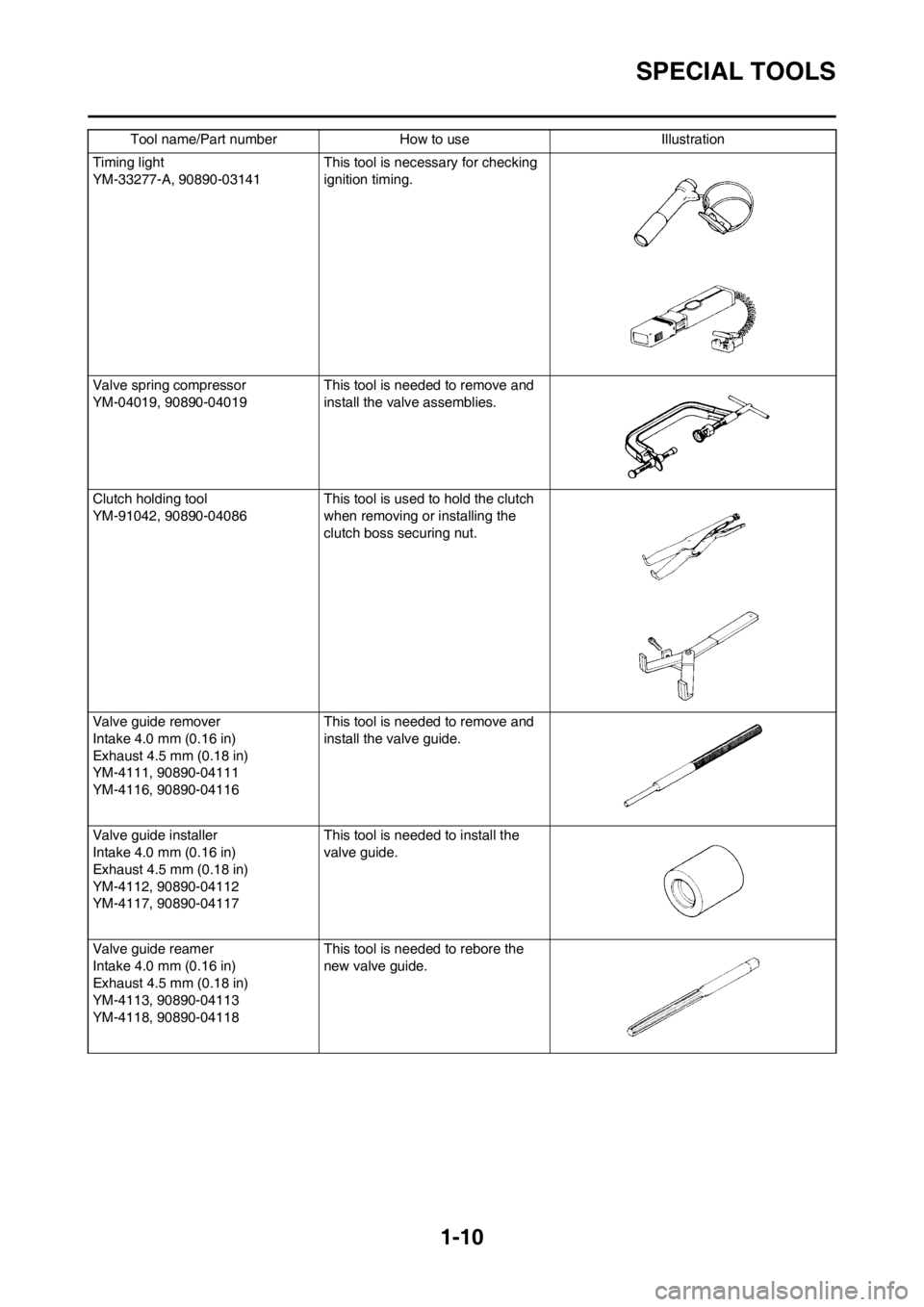
SPECIAL TOOLS
Timing light
YM-33277-A, 90890-03141 This tool is necessary for checking
ignition timing.
Valve spring compressor
YM-04019, 90890-04019 This tool is needed to remove and
install the valve assemblies.
Clutch holding tool
YM-91042, 90890-04086This tool is used to hold the clutch
when removing or installing the
clutch boss securing nut.
Valve guide remover
Intake 4.0 mm (0.16 in)
Exhaust 4.5 mm (0.18 in)
YM-4111, 90890-04111
YM-4116, 90890-04116This tool is needed to remove and
install the valve guide.
Valve guide installer
Intake 4.0 mm (0.16 in)
Exhaust 4.5 mm (0.18 in)
YM-4112, 90890-04112
YM-4117, 90890-04117This tool is needed to install the
valve guide.
Valve guide reamer
Intake 4.0 mm (0.16 in)
Exhaust 4.5 mm (0.18 in)
YM-4113, 90890-04113
YM-4118, 90890-04118This tool is needed to rebore the
new valve guide. Tool name/Part number How to use Illustration
Page 21 of 198
1-11
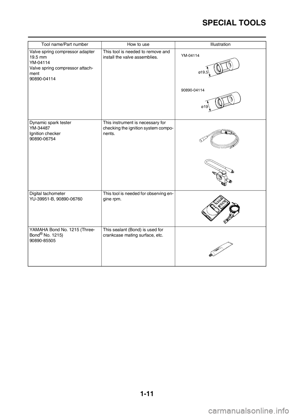
SPECIAL TOOLS
Valve spring compressor adapter
19.5 mm
YM-04114
Valve spring compressor attach-
ment
90890-04114This tool is needed to remove and
install the valve assemblies.
Dynamic spark tester
YM-34487
Ignition checker
90890-06754 This instrument is necessary for
checking the ignition system compo-
nents.
Digital tachometer
YU-39951-B, 90890-06760 This tool is needed for observing en-
gine rpm.
YAMAHA Bond No. 1215 (Three-
Bond
® No. 1215)
90890-85505 This sealant (Bond) is used for
crankcase mating surface, etc.
Tool name/Part number How to use Illustration
Page 28 of 198

2-2
GENERAL SPECIFICATIONS
Carburetor:Type FCR-MX39
Manufacturer KEIHIN
Spark plug: Type/manufacturer CR8E/NGK (resistance type)
Gap 0.7–0.8 mm (0.028–0.031 in)
Clutch type: Wet, multiple-disc
Transmission: USA, CDN EUROPE, AUS, NZ, ZA Primary reduction system Gear ←
Primary reduction ratio 3.353 (57/17) ←
Final drive Chain ←
Secondary reduction ratio 3.846 (50/13) 3.923 (51/13)
Transmission type Constant mesh, 5-speed ←
Operation Left foot operation ←
Gear ratio:
1st 2.143 (30/14) ←
2nd 1.750 (28/16) ←
3rd 1.444 (26/18) ←
4th 1.222 (22/18) ←
5th 1.042 (25/24) ←
Chassis: USA, CDN EUROPE AUS, NZ, ZA
Frame type Semi double cra-
dle ←←
Caster angle 27.21°27.12°27.32°
Trail 121.3 mm (4.78
in) 119.9 mm (4.72
in)122.1 mm (4.81
in)
Tire:
Type With tube
Size (front) 80/100-21 51M
Size (rear) 100/90-19 57M
Tire pressure (front and rear) 100 kPa (1.0 kgf/cm
2, 15 psi)
Brake:
Front brake type Single disc brake
Operation Right hand operation
Rear brake type Single disc brake
Operation Right foot operation
Suspension: Front suspension Telescopic fork
Rear suspension Swingarm (link type monocross suspension)
Shock absorber: Front shock absorber Coil spring/oil damper
Rear shock absorber Coil spring/gas, oil damper
Wheel travel: USA, CDN EUROPE, AUS, NZ, ZA Front wheel travel 300 mm (11.8 in) ←
Rear wheel travel 317 mm ( 12.5 in) 312 mm (12.3 in)
Electrical: Ignition system CDI magneto
Page 36 of 198
2-10
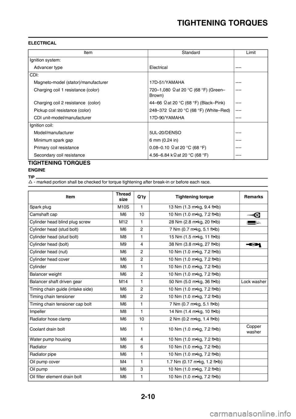
TIGHTENING TORQUES
ELECTRICAL
TIGHTENING TORQUES
ENGINE
△- marked portion shall be checked for torque tightening after break-in or before each race.
Item Standard Limit
Ignition system:
Advancer type Electrical ----
CDI:
Magneto-model (stator)/manufacturer 17D-51/YAMAHA ----
Charging coil 1 resistance (color) 720–1,080 Ωat 20 °C (68 °F) (Green–
Brown)----
Charging coil 2 resistance (color) 44–66 Ωat 20 °C (68 °F) (Black–Pink) ----
Pickup coil resistance (color) 248–372 Ωat 20 °C (68 °F) (White–Red) ----
CDI unit-model/manufacturer 17D-90/YAMAHA ----
Ignition coil:
Model/manufacturer 5UL-20/DENSO ----
Minimum spark gap 6 mm (0.24 in) ----
Primary coil resistance 0.08–0.10 Ωat 20 °C (68 °F) ----
Secondary coil resistance 4.56–6.84 kΩat 20 °C (68 °F) ----
ItemThread
sizeQ'ty Tightening torque Remarks
Spark plug M10S 1 13 Nm (1.3 m•kg, 9.4 ft•lb)
Camshaft cap M6 10 10 Nm (1.0 m•kg, 7.2 ft•lb)
Cylinder head blind plug screw M12 1 28 Nm (2.8 m•kg, 20 ft•lb)
Cylinder head (stud bolt) M6 2 7 Nm (0.7 m•kg, 5.1 ft•lb)
Cylinder head (stud bolt) M8 1 15 Nm (1.5 m•kg, 11 ft•lb)
Cylinder head (bolt) M9 4 38 Nm (3.8 m•kg, 27 ft•lb)
Cylinder head (nut) M6 2 10 Nm (1.0 m•kg, 7.2 ft•lb)
Cylinder head cover M6 2 10 Nm (1.0 m•kg, 7.2 ft•lb)
Cylinder M6 1 10 Nm (1.0 m•kg, 7.2 ft•lb)
Balancer weight M6 2 10 Nm (1.0 m•kg, 7.2 ft•lb)
Balancer shaft driven gear M14 1 50 Nm (5.0 m•kg, 36 ft•lb) Lock washer
Timing chain guide (intake side) M6 2 10 Nm (1.0 m•kg, 7.2 ft•lb)
Timing chain tensioner M6 2 10 Nm (1.0 m•kg, 7.2 ft•lb)
Timing chain tensioner cap bolt M6 1 7 Nm (0.7 m•kg, 5.1 ft•lb)
Impeller M8 1 14 Nm (1.4 m•kg, 10 ft•lb)
Radiator hose clamp M6 10 2 Nm (0.2 m•kg, 1.4 ft•lb)
Coolant drain bolt M6 1 10 Nm (1.0 m•kg, 7.2 ft•lb)Copper
washer
Water pump housing M6 4 10 Nm (1.0 m•kg, 7.2 ft•lb)
Radiator M6 6 10 Nm (1.0 m•kg, 7.2 ft•lb)
Radiator pipe M6 1 10 Nm (1.0 m•kg, 7.2 ft•lb)
Oil pump cover M4 1 1.7 Nm (0.17 m•kg, 1.2 ft•lb)
Oil pump M6 3 10 Nm (1.0 m•kg, 7.2 ft•lb)
Oil filter element drain bolt M6 1 10 Nm (1.0 m•kg, 7.2 ft•lb)
Page 46 of 198

2-20
CABLE ROUTING DIAGRAM
1. Sub-wire harness
2. Hot starter cable
3. Oil hose
4. Neutral switch lead
5. Radiator hose 2
6. Clamp
7. Ignition coil lead
8. CDI magneto lead
9. Neutral switch lead coupler
10. CDI unit lead coupler11. Radiator breather hose
12. Hot starter cable protector
13. Rubber cap
14. Throttle position sensor lead
15. Cylinder head breather hose
16. Throttle position sensor lead
coupler
17. Tension pipe
18. Radiator mounting boss
19. Cylinder head breather hose20. Throttle position sensor tube
clamp
E K
E F GHH
F IJ A
AB
D
D CJ
C
G
B
K
E
M
M
H-H
K-K
E-E
D-D
M-M
F-F
A-A
I
L
L
Page 47 of 198

2-21
CABLE ROUTING DIAGRAM
A. Pass the hot starter cable over
the radiator mounting boss.
B. Pass the throttle position sensor
lead under the hot starter cable.
C. Fasten the throttle position sen-
sor lead and the hot starter ca-
ble.
D. Locate the clamp between the
hot starter cable protector and
rubber cap.
E. Fasten the neutral switch lead
below the oil hose. and pass the
neutral switch lead on the inside
of the oil hose.
F. Pass the neutral switch lead on
the inside of the oil hose.
G. Fasten the neutral switch lead,
CDI magneto lead, and radiator
breather hose onto the frame.
They should all be clamped
above the engine bracket to the
left of the downtube of the
frame. The clamp ends should
face backward and the rest out-
side of the frame.
H. Pass the clutch cable through
the cable guide.
I. Pass the neutral switch lead and
CDI magneto lead behind the
frame.
J. Pass the hot starter cable on the
inside of the cylinder head
breather hose.
K. Fit the coupler projection into the
hole in the cover.
L. Fasten the sub-wire harness on
the CDI unit bracket.
M. Fasten the sub-wire harness at
the position-taped portion.
N. Pass each lead under the
clamp. Locate the CDI magneto
lead on the outside of the igni-
tion coil lead. Locate the throttle
position sensor lead, neutral
switch lead, CDI magneto lead
and ignition coil lead so that they
do not lie one on another.
O. Fasten the sub-wire harness to
the CDI unit bracket with the
clamp ends located under the
bracket.
P. Fasten the neutral switch lead,
throttle position sensor lead,
CDI magneto lead and ignition
coil lead. Fasten them around
the periphery of the recess be-
tween the tension pipe and radi-
ator mounting boss on the
frame.
Q. Locate the clamp ends within
the arrowed range. Assure that
the clamp end does not contact
the cylinder head breather hose.R. Pass the radiator breather hose
on the outside of the CDI mag-
neto lead and neutral switch
lead.
S. Fasten the throttle position sen-
sor lead and hot starter cable.
Fasten them between the cylin-
der head breather hose and
throttle position sensor tube
clamp. Fasten the clamp with its
ends toward the right-side of the
frame and cut off the other end
with 3 to 5 clamp holes left in it.
T. Locate the radiator breather
hose end above the down tube
and between the oil hose and
engine guard.
U. Fasten the neutral switch lead
above the oil hose, and pass the
neutral switch lead on the inside
of the oil hose.
Page 48 of 198
2-22
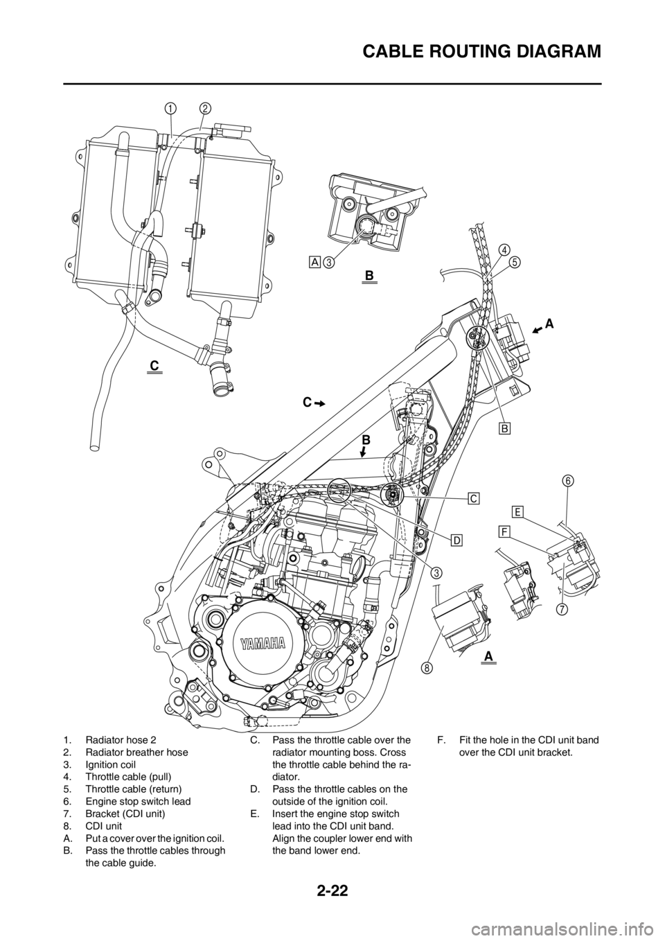
CABLE ROUTING DIAGRAM
1. Radiator hose 2
2. Radiator breather hose
3. Ignition coil
4. Throttle cable (pull)
5. Throttle cable (return)
6. Engine stop switch lead
7. Bracket (CDI unit)
8. CDI unit
A. Put a cover over the ignition coil.
B. Pass the throttle cables through
the cable guide.C. Pass the throttle cable over the
radiator mounting boss. Cross
the throttle cable behind the ra-
diator.
D. Pass the throttle cables on the
outside of the ignition coil.
E. Insert the engine stop switch
lead into the CDI unit band.
Align the coupler lower end with
the band lower end.F. Fit the hole in the CDI unit band
over the CDI unit bracket.
CA
BB
A
C
Page 55 of 198

3-5
PRE-OPERATION INSPECTION AND MAINTENANCE
PRE-OPERATION INSPECTION AND MAINTENANCE
Before riding for break-in operation, practice or a race, make sure the machine is in good operating condition.
Before using this machine, check the following points.
GENERAL INSPECTION AND MAINTENANCE
Item Routine Page
CoolantCheck that coolant is filled up to the radiator cap. Check the cool-
ing system for leakage.P.3-6 – 7
FuelCheck that a fresh gasoline is filled in the fuel tank. Check the fuel
line for leakage.P.1-13
Engine oilCheck that the oil level is correct. Check the crankcase and oil line
for leakage.P.3-9 – 10
Gear shifter and clutchCheck that gears can be shifted correctly in order and that the
clutch operates smoothly.P.3-7
Throttle grip/HousingCheck that the throttle grip operation and free play are correctly
adjusted. Lubricate the throttle grip and housing, if necessary.P.3-7 – 8
Brakes Check the play of front brake and effect of front and rear brake. P.3-14 – 16
Drive chainCheck drive chain slack and alignment. Check that the drive chain
is lubricated properly.P.3-17 – 18
WheelsCheck for excessive wear and tire pressure. Check for loose
spokes and have no excessive play.P.3-20 – 21
SteeringCheck that the handlebar can be turned smoothly and have no ex-
cessive play.P.3-21 – 22
Front forks and rear shock
absorberCheck that they operate smoothly and there is no oil leakage.
P.3-18 – 20
Cables (wires)Check that the clutch and throttle cables move smoothly. Check
that they are not caught when the handlebars are turned or when
the front forks travel up and down.—
Exhaust pipe Check that the exhaust pipe is tightly mounted and has no cracks. P.4-3 – 6
Rear wheel sprocket Check that the rear wheel sprocket tightening bolt is not loose. P.3-17
Lubrication Check for smooth operation. Lubricate if necessary. P.3-23
Bolts and nuts Check the chassis and engine for loose bolts and nuts. P.1-15
Lead connectorsCheck that the CDI magneto, CDI unit, and ignition coil are con-
nected tightly.P.1-7
SettingsIs the machine set suitably for the condition of the racing course
and weather or by taking into account the results of test runs be-
fore racing? Are inspection and maintenance completely done?P.7-1 – 10
Page 61 of 198
3-11
ENGINE
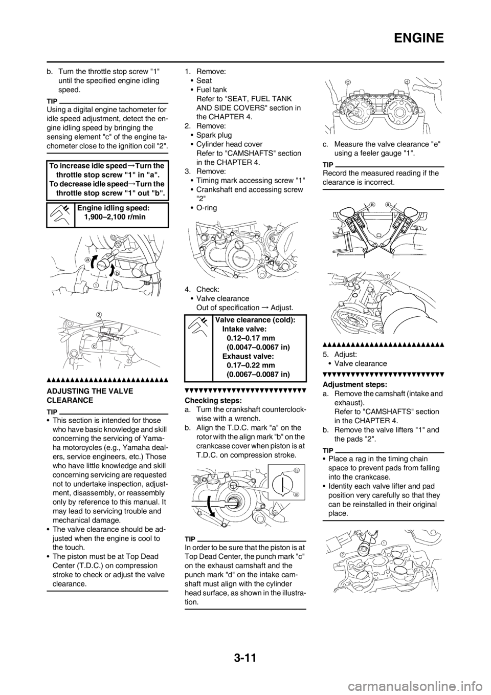
b. Turn the throttle stop screw "1"
until the specified engine idling
speed.
Using a digital engine tachometer for
idle speed adjustment, detect the en-
gine idling speed by bringing the
sensing element "c" of the engine ta-
chometer close to the ignition coil "2".
ADJUSTING THE VALVE
CLEARANCE
• This section is intended for those
who have basic knowledge and skill
concerning the servicing of Yama-
ha motorcycles (e.g., Yamaha deal-
ers, service engineers, etc.) Those
who have little knowledge and skill
concerning servicing are requested
not to undertake inspection, adjust-
ment, disassembly, or reassembly
only by reference to this manual. It
may lead to servicing trouble and
mechanical damage.
• The valve clearance should be ad-
justed when the engine is cool to
the touch.
• The piston must be at Top Dead
Center (T.D.C.) on compression
stroke to check or adjust the valve
clearance.
1. Remove:
•Seat
•Fuel tank
Refer to "SEAT, FUEL TANK
AND SIDE COVERS" section in
the CHAPTER 4.
2. Remove:
• Spark plug
• Cylinder head cover
Refer to "CAMSHAFTS" section
in the CHAPTER 4.
3. Remove:
• Timing mark accessing screw "1"
• Crankshaft end accessing screw
"2"
• O-ring
4. Check:
• Valve clearance
Out of specification→Adjust.
Checking steps:
a. Turn the crankshaft counterclock-
wise with a wrench.
b. Align the T.D.C. mark "a" on the
rotor with the align mark "b" on the
crankcase cover when piston is at
T.D.C. on compression stroke.
In order to be sure that the piston is at
Top Dead Center, the punch mark "c"
on the exhaust camshaft and the
punch mark "d" on the intake cam-
shaft must align with the cylinder
head surface, as shown in the illustra-
tion.
c. Measure the valve clearance "e"
using a feeler gauge "1".
Record the measured reading if the
clearance is incorrect.
5. Adjust:
• Valve clearance
Adjustment steps:
a. Remove the camshaft (intake and
exhaust).
Refer to "CAMSHAFTS" section
in the CHAPTER 4.
b. Remove the valve lifters "1" and
the pads "2".
• Place a rag in the timing chain
space to prevent pads from falling
into the crankcase.
• Identity each valve lifter and pad
position very carefully so that they
can be reinstalled in their original
place.
To increase idle speed→Turn the
throttle stop screw "1" in "a".
To decrease idle speed→Turn the
throttle stop screw "1" out "b".
Engine idling speed:
1,900–2,100 r/min
Valve clearance (cold):
Intake valve:
0.12–0.17 mm
(0.0047–0.0067 in)
Exhaust valve:
0.17–0.22 mm
(0.0067–0.0087 in)